ITW Simco-Ion MEB/SS-50 User manual

INST 13051312-
Simco-Ion Electrostatic Neutralizer
Static Neutralizing Bar MEB / SS-50
INSTRUCTIONS
Installation/Operation/Maintenance
CAUTION
It is important that these instructions be read and understood before
installation or operation. Failure to follow these instruction so could
result in serious personal injury and/or damage to the equipment. At
the end of this manual, a written warranty is provided. This should
be stared in a safe place.
Notes to Users
WARNING
This equipment is not constructed for classified (hazardous)
environment. It cannot be used where it will be exposed to ignitable
or corrosive materials and gases.
CAUTION
This equipment employs high voltage. Please follow the operating instructions
carefully in order to minimize electrical shock hazard.
This equipment is intended for use in electrostatic processes that are free from water,
oil and other conductive contaminants. Exposure to such contaminants will cause
failure of the electrical insulation system in the product.
This equipment should not be operated in an ambient with corrosive fumes of
acid/alkali or corrosive gases such as chlorine.
The equipment is designed to be used with specific Simco-Ion Power unit. Its
performance and durability cannot be guaranteed if any other power supply used.
The Power unit, in turn, shall be connected to proper utility line. The utility line
conditions are indicated on the nameplate of the Power unit.
The Static Neutralizing Bars and Power units should be mounted in position and all
high voltage connections completed with high voltage cables properly secured before
the system is connected to the utility lines. Flexing the high voltage cables with power
on can cause failure of the insulation system.
The equipment must have proper grounding. Without proper grounding there may
be electrical shock/fire hazard.
During normal use of this product, there should be no visible spark. If any spark is
observed, please turn off power and clean the unit following proper maintenance
procedure. In case sparking continues, switch off the Power unit and contact us or
our sales representatives in your area. Inspection, exchange and repair service will be
provided in accordance with the warranty conditions.
The neutralizing electrodes in this product consist of sharp needles. Please take
precautions against injury. Periodic maintenance, such as cleaning of needle
electrodes, is necessary for satisfactory performance of the equipment.
This equipment is likely to be damaged if dropped. In such an event, it should be
carefully examined and any necessary repairs be made by an authorized technician.
The equipment will produce considerable electrical noise and insulation might burn if
the unit is damaged.
-page 1-

Thank you for buying Simco-Ion products. This equipment will meet
your expectations and provide safe operation when it is properly
.installed and maintained
Checking the contents of package
Please carefully remove the equipment from the carton and inspect. Note
any damage that might have occurred during shipment. Empty the carton to
ensure that small parts are not discarded.
If any damage has occurred during shipment, the local carrier should be
notified at once. A report should be forwarded to SIMCO JAPAN, INC.
The address and other relevant informations are written on the back cover
page.
Package Contents
1 Static bar and high voltage cable typically 3m 1 pc.)()
2 Mounting Device)Model Device
MEB MEB Clamp 2 pcs.
MEB CE/RS X1/2 flat plate 2 pcs.-()
SS-50 X1/2 flat plate 2 pcs.()
SS-50 CE/RS X1/2 flat plate 2 pcs.-()
A kind of bracket different from the above-mentioned by prior meeting might be
attached.
3 Plastic ties and Plastic blocks 1 set.)
4 Daily Inspection Label 1 pc.)
5 Instructions Manual / Warranty 1 pc.)
Please check if any part is missing or does not have
satisfactory finish. Contact us or our agents
immediately in the event of such occurrence.
-page 2-
CONTENTS
Notes to Users...................................................................................page 1
Receipt of equipment.......................................................................page 2
Contents.............................................................................................page 3
Packing articles and accessories.......................................................page 3
Section 1. General description..........................................................page 4
Section 2. Specifications...................................................................page 5
Section 3. Principle of Operation.....................................................page 7
Section 4. Installation........................................................................page 8
Section 5. Operation........................................................................page 13
Section 6. Maintenance...................................................................page 13
Section 7. Abnormal conditions.....................................................page 17
Section 8. Replaceable parts...........................................................page 18
Section 9. Other products...............................................................page 18
Model A3030/A3031 connectors....................................................page 19
Simco-Ion Air Bars.........................................................................page 20
Simco-Ion EQUIPMENT REPAIR WARRANTY....................enclosed
Explanation of Symbols:
WARNING
ATTENTION / CAUTION
ELECTRIC SHOCK HAZARD
-page 3-

SECTION 1. General Description
Simco-Ion Static Bars are used to neutralize static charge. These are used with Simco-Ion
Power unit. Each type is designed to be used with a particular type of Power unit. ME,
MEB, P-SH --- each of these static bar models needs a single phase AC 7 kV ± 7 %
Power unit. SS-50 needs a single phase AC 4 kV ± 7 % Power unit.
NOTE:
A mistake in choosing a correct combination of Static Bar and Power unit
might damage the units. The following table provides guidelines for the type
of Static Bars and the corresponding Power units.
B a r Shape color Size Special Power unit
model [mm] Features model
Power Unit 47MEB Grey/SilverRectangular 16 × 19 Light Power Unit 150[shockless section Inexpensiveor (Only thetype] CE:RoSH.CEBlue/Silver shielded cablemarking hasRS:RoSH )corresponded
F167J
F167
Power Unit 47SS-50 Rectangular White/Black 13 × 17 High efficiency Power Unit 150[Non- section or or CE:RoSH.CE Only theshockless] White/Silver 16 arking×19 m (shielded cable(CE/RS) RS:RoSH has )corresponded
F164J
Sometimes Ion balance circuits are needed to balance the concentration of ions produced
by charge neutralizers. Ion balance circuits are not used with Shockless type eliminators.
However, SS-50 (hot or non-shockless type) bar can have an Ion balance circuit by using
Power Unit 4. For the details on the number of eliminators that can be connected with a
Power unit, please contact our sales division.
Simco-Ion Static Bars use AC high voltage Power units. Shockless static eliminators use
capacitive coupling to limit the amount of electrical energy that can be drawn from an
electrode when it is shorted to ground. Because of the limited energy that can be drawn
from the electrode, these type of static eliminators are inherently safe from shock hazard.
In the non-shockless type (hot type) eliminators, needle electrodes have direct contact
with high voltage conductor.
-page 4-
CAUTION
F167, F167J, F164J Power units do not include any failure detection
circuit. Consequently, in the event of any short-circuit or sparking, the
high voltage output is not disconnected. If this continues, the insulation of
the Static Bar/high voltage cable will be burnt. Periodic checking and
maintenance should be done to prevent this from happening.
Power Unit 47 and Power Unit 150 have failure detection circuits inside;
therefore, insulation damage can be prevented.
SECTION 2. Specifications
2.1 Common characteristics
Static Charge NeutralizerFunction:
About0to40 ,10to85%RHAmbient conditions: ℃
About 10,000 hours (based on 8 h/d, 250 d/y, 5 years)Life expectancy: One year after shipmentWarranty:
-page 5-

2.2 The following table presents the other characteristics of the different types of
bars.
Model MEB SS 50-
--Certification Certified*
Rated volts/ AC 7 kV;shockless AC 4 kV; non-shockless
construction
Overall [mm] 16 × 1916 × 19 13 × 17
Dia / W × H
Approximate 330 570 430 690
Weight [g/m]
Ionizing
emitter Stainless Steel/Titanium
material
Anodized AnodizedGrounding
electrode SUS304 SUS304Aluminum Aluminum
(white) (black)material
Insulation PVC Teflon
material
White silicone H-red/White White siliconeHigh voltage MEB-black/ shielding silicone shieldingcable White silicone small dia.large dia.
High voltage
c a b l e Shielding available with silicone cable only
shielding
HV cable end Model A3030 Model A3031
connector
Type of cable Straight/Right angle Straight only
direction
Optional None Standard back NoneMounting studstud
CE:CE and RoSH CE:CE and RoSHCE m None Nonearking RS:RoSH RS:RoSH/RoSH
Air bar Optional
*: Japanese Ministry of Labor or UL (USA) certified
-page 6-
NOTE:
For detailed drawings, please contact our sales division.・Weight of bars shown in the table above is only approximate.・High voltage cable is, normally, not shielded. Standard high voltage cable is・covered by semi-transparent polyethylene tube and grey colored spiral.
Silicone cable is not approved by either Japanese Ministry of Labor or UL・(USA).
For any further information on any of the products, please contact our・sales division.
SECTION 3. Principle of Operation
A Simco-Ion static eliminator consists of ionizing electrodes, high voltage cable and a
Power unit. The ionizing electrodes are sharpened needle tips at high voltage, positioned
near ground electrode.
Simco-Ion static eliminator operates as follows:
1) When the power switch is turned on, it produces high voltage.
2) Because of intense electric field at the emitter needle tips, corona discharge is initiated.
Air around the needles is ionized and positive and negative ions are produced.
3) As the unlike charges attract, the charged object that needs to be neutralized attracts
ions of opposite polarity until it is neutralized.
Fig.1 shows how an object, charged statically to 20 50 kV can be neutralized, typically,~
downto0.1to0.2kV.
Fig.1 Neutralization of charged object using a static bar
-page 7-

SECTION 4. Installation
CAUTION
The installation of the Power unit, high voltage cable and static bars must・be carried out by a trained electrician.
Ionizing needle electrodes are very sharp and can cause considerable・physical injury. Please handle Static Bars with care.
Complete all wirings before switching on the power.・
4.1 Location
Best locations are usually just ahead of place where static charge gives trouble.・The material to be neutralized should not be in contact with another surface as it・passes the static bar, since static charges cannot be easily neutralized if the object is
not free.
Static bars should be pointing directly towards the object to be neutralized.・Static bar should be placed more than 15 mm and less than 50 mm from the object.・High efficiency bars can be located further than this. All bars can be efficient at close
distance. In case, the charged object is moving at high speed, make the distance close,
if possible.
Between Static Bars and charged material to be neutralized, there should be no other・object.
The bar cannot be cut or bent.・
CAUTION
A neutralized object is not static-proof. It can get charged again by friction.・For a thick object ( 0.1 mm), neutralization is necessary on both the・>
surfaces. Two Static Bars will be required, one for each surface.
In case the speed of the object is high, it is better to have more than one・bar. The distance between two nearest faces of two bars, placed side by
side should be about 25 mm.
Fig.2 Static bar location
-page 8-
4.2 Mounting
Static bars may be provided with mounting brackets that can be bent and twisted to・support them from the frame of the machine or convenient stationary shafts that span
the machine. Studs may also be provided for direct mounting. See the specification
table on page 6 for details.
The case of the Static Bars must be grounded. Grounding resistance should be checked・with a tester. It should be 100 . Improper grounding affects neutralization≦Ω
performance and could lead to electrical shock hazard.
Do not cover the ionizing points.・A Static Bar should not touch the object to be neutralized.・
CAUTION
Do not twist or bend the bar. Do not put any pressure on it.・For installing air bar, please read page 20 and 21.・
Fig.3 Static bar installation
4.3 High Voltage Cable Installation
CAUTION
The high voltage wiring should be done by a trained technician.・The high voltage cable is specially constructed for this product. Do not・replace it with any other wire. Life expectancy of high voltage cable is
about 10,000 hours.
Do not turn the Power unit ON until all connections and wiring are・completed.
-page 9-

Cable Assembly
The static bar MEB usually provides the high voltage line for a special polyethylene tube
and the spiral for mechanical protection. The static bar SS-50 usually provides the high
voltage line for a special spiral for mechanical protection.
There are two types of high voltage connectors available. In SS-50, model A3031 type
connector is used. In all other bars, model A3030 is used. Further information on
connectors can be obtained from the specification table. For the details on construction,
see page 19.
The static bar MEB doesn't have any space between terminals of aNOTE: combination and a static bar in the spiral and the polyethylene tube
either ; also there should be no space between the
spiral-polyethylene tube combination and the high voltage connector.
The static bar SS-50 doesn't have any space between the spiral and
the static bar terminal either ; also there should be no space
between the spiral and the high voltage connector.
Laying of the high voltage cable
1) Decide on a wiring route from the static bar to the Power unit.
2) The high voltage connectors are sensitive to damage by mechanical movement. In
order to avoid any damage, fix the high voltage cable near the Static bar and the
Power unit first and then at about 1 m intervals between these points. Attach the high
voltage cable to the machine frame, etc., by using cable holding plastic blocks and
"plastic wire tie". Shielded cables do not need any plastic block.
3) The power unit, cable and the static bar should be located in an easily accessible place
such that the any replacement in future can be easily carried out.
CAUTION
High voltage cable is special; pulling, sharp bending could damage it. Also,・metal powder and water should be avoided on the cable.
Do not tie the cables together if each cable is connected to a separate・Power unit.
Fig.4 High voltage cable installation
-page 10-
The minimum bending radius permitted is about 60 mm. While installing the・cable, avoid contact with the pointed corners of metal frame. Pointed corners
could damage the insulation and eventually lead to failure.
Fig.5 Bending of high voltage cable
The following figure shows how not to apply pressure on the high voltage cable.・
Fig.6 Pressure on high voltage cable
In case of a shielded cable, the shield must be connected to the ground terminal・of a Power unit and then connected to ground as shown below in Fig.7. If
grounding is not properly done, there is a risk of electrical shock/fire hazard.
The shielded cable cannot be shortened easily. If it is necessary, please contact・us or our agents.
Electrical discharge generates noise that might interfere with electrical signal in・neighboring circuits. Significant reduction in noise can be obtained by using
shielded high voltage cable.
-page 11-

ATTENTION
Unshielded high voltage cable cannot be replaced by shielded high voltage・cable except when silicone cable is used.
Do not use a metal tube or metallic tape for shielding. Use a proper・shielded cable. The shield must be grounded properly or it could be an
electrical shock/fire hazard.
If shielded cable is needed, please contact our sales division.・
4.4 High voltage labels
The three attached labels should be used on the high voltage cable. Simco-Ion provides(
)labels written in Japanese.
4.5 Type of connectors and number of parallel connections
The following table provides information on the type of connectors and their applications.
Type Configuration High Voltage Static-bar side cable Connecting
cable units end connector method
3wire Y 1to1 3 2-4Ssolderlessring M4Screw~
connector terminal
T- 2 T 1 to A3030/ A3031 By hand≧1
connector
Preconnector Straight 1 to 1 A3030/ A3031 By hand
HV parallel More than 2 1 to 2 6 A3030 US/ By hand~
connector p a r a l l e l A3031 US
outputs
HV parallel More than 2 2 to 2 2 - 4S solderless ring M4 Screw≧≧
connection p a r a l l e l terminal
box outputs
NOTE:
Do not use any connector other than that made by Simco-Ion.・Contact our sales division for detailed information and figure.・
-page 12-
4.6 High voltage cable connection at the power unit
Proper connector attached to the high voltage cable terminal is used to connect the・high voltage cable to the Power unit. For details, please refer to the instruction manual
foryourPowerunit.
If necessary, please contact us for a copy of the instruction manual for the Power unit.・
SECTION 5. Operation
AnON/OFFswitchonthePowerunitisusedtoturnastaticbaronandoff.Pleaseread
the manual of instructions for your Power unit before turning it on.
SECTION 6. Maintenance
A static bar employs high voltage and is a special product. If regular maintenance is
neglected, their may be deterioration of neutralizing performance. There is also a
possibility of insulation burn-out.
6.1 Cleaning of a static neutralizing bar
CAUTION
Turn off the power supply at the power unit at the time of cleaning.・There is the possibility of injury because of sharp needles.・Never use metal brush wire .・()
Do not use any organic solvent other than methanol and IPA , water,・()
paint thinner etc..
In case alcohol is used, do not pour it on the bar; use a few drops on a・piece of cloth and use it to clean the bar. Let it dry completely before
power supply is turned on.
Periodically remove dirt possibly the deposition of white powder or black/dark brown(
powder with a nylon brush. In order to remove dirt that cannot be removed by brushing)
alone paint, ink, oil , a little pure methanol or pure IPA may be used.()
Fig.8Cleaningofstaticbarsbynylonbrush
-page 13-

6.2 Maintenance of the high voltage cable
Periodically check the high voltage cable for color change or damage on the external tube
that protects the cable. This type of minor problem that does not involve the high voltage
cable itself, can be easily taken care of by putting some insulation tape around this region.
In case a high voltage cable becomes dirty with oil, water etc., please wipe it off with a
piece of cloth. In case the high voltage cable itself is damaged, contact our sales division
as a replacement of the static bar may be necessary.
CAUTION
Turn off the Power unit before removing a high voltage cable from the Power
unit side. The other side of the cable is permanently connected to the bar and
cannot be removed.
6.3 Important Initial checks
The following checks should be carried out by a trained electrician.
Visual check:
Check if any of the needles is bent or if there is any other sign of abnormality. In this
case, the bar might have to be replaced.
Spark test:
WARNING
When conducting the following test, be certain that no flammable solvents or
gas is in the ambient air. Also, switch off any computer or sequencer to
.protect against electrical transients and noise
Steps:
1Useasmallscrew-driver.)
2 Switch on the Power unit. Holding the insulated part of the screw-driver, touch the)metal shaft to the grounded case and bring it close to ionizing needles.
-page 14-
Fig.9 Spark test
Troubleshooting for spark test:
Bar type Model Type of spark Comment Cause Countermeasure
No spark NG Insulation Replace bar/Shockless MEB problem in repair Power unit
bar/cable or
problem
with the
Power unit
White spark, OK
2~ 3 mm long
5~ 8 mm long NG Insulation Replace bar
strong red problem
spark between
electrodes
Non- SS-50 No spark NG Insulation Replace bar/
shockless problem in repair Power unit
hot bar/cable or() problem
with the
Power unit
5~ 8 mm long OK
strong red
spark
-page 15-

Grounding resistance check
Measure the resistance between the casing of static neutralizer, machine frame and the
Power unit. The meter should read less than 100 .Ω
Neutralizing performance check
This test should be done periodically. The neutralization performance should be measured
with an electrostatic fieldmeter.
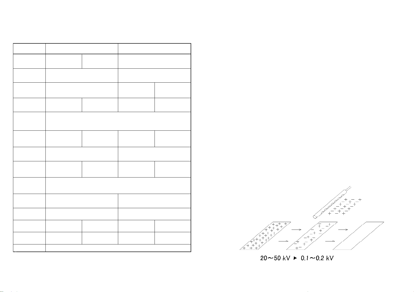
Measure the initial voltage of the charged object.・Turn the static bar on and use it to neutralize a charged object.・Measure the final voltage using the fieldmeter.・
If there is efficient neutralization, the voltage should decrease quickly (see Fig.1). Please
note that for efficient neutralization, the static bar should be located close to the charged
object as mentioned earlier.
Insulation resistance
If spark test and neutralization performance are found unsatisfactory, the insulation
resistance of the bar should be checked. The following table provides the course of action
to be taken depending on the insulation resistance.
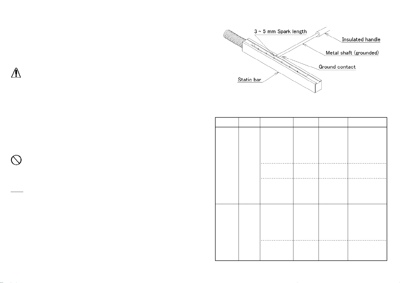
Bar type Model Measuring points Equipment Comments
used
Shockless MEB Needle - HV cable 1 G : OKDC 1,000 V ≧Ω
end 1 G ~ 100 M : barmeggar ΩΩ
needs to be cleaned
100 M : bar needs to<Ω
be replaced.
HV cable end - DC 10,000 V 10 G : OK≧Ω
grounding meggar 10 G ~ 100 M : barΩΩ
e l e c t r o d e needs to be cleaned.
connected to 100 M : bar needs to<Ω
ground be replaced.
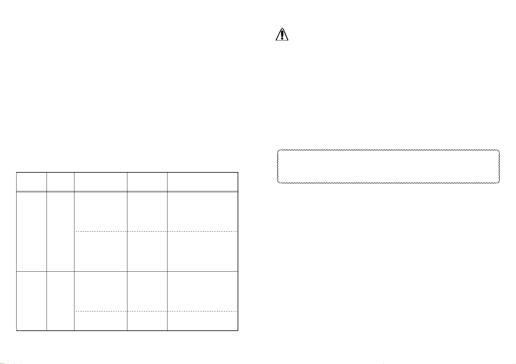
Non- SS-50 HV cable end - DC 1,000 V 1 G : OK≧Ω
shockless grounding meggar 1 G ~ 100 M : barΩΩ
hot e l e c t r o d e needs to be cleaned.() connected to 100 M : bar needs to<Ω
ground be replaced.
Needle - HV cable Tester 10 : OK≦Ω
end 10 : replace bar.>Ω
-page 16-
ATTENTION
Each needle electrode in shockless bars is insulated. During insulation・resistance measurements, each needle should be tested separately. In hot
bar all needle electrodes are directly connected to high voltage.
Disconnect the cable at the Power unit end while carrying out the・resistance measurements.
In insulation resistance measurements above, high voltage cable-end refers・to the spring belonging to the connectors, such as in A3030 etc..
If, even after cleaning, the insulation resistance of the bar does not become・normal, it might need replacement.
Even if the insulation resistance values are normal, regular cleaning of the・needles is necessary.
If a 10,000 V meggar is not available, a 1,000 V meggar can be used. The・same criteria of success or failure as for other 1,000 V meggar tests can be
accepted in this case.
In case a repair is needed, please contact Simco Japan's sales division or an
authorized agent in your area with the details of the defects, test results,
observations etc. and ask for an estimate. Any inspection and repair will be
treated in accordance with the warranty provided at the end of this manual.
SECTION 7. Abnormal conditions
7.1 Spark from an ionizing needle electrode
During normal operation, there should be no visible spark. If spark is observed, the bar
should be cleaned properly see section 6.1 . If the sparking continues even after()
cleaning, please switch off the Power unit and contact us directly or an authorized agent
in your area.
7.2 Other abnormalities
In case the following abnormalities are observed, please switch off the Power unit and
contact us directly or an authorized agent in your area.
a Sparking from any part of a static bar or high voltage cable)
b Change in shape of a static bar)
c Melting or burning of high voltage cable)
-page 17-

SECTION 8. Replaceable parts
There is no replaceable part with the bar or the high voltage cable.・If the protective tube on high voltage cable changes color or is damaged, reinforce with・insulation tape or contact us for replacement.
High voltage connectors (A3030 or A3031) should be replaced if any crack is observed.・
SECTION 9. Other products
Type Application Model
Fieldmeter Measurement of voltage on a FMX 004-
charged object
S u r f a c e Measurement of surface resistance, ST 4-
resistance grounding resistance
meter
Static analyzer Measurement of decay time, offset EA 5J-
voltage, etc.(Charge plate
monitor)
High voltage Measurement of Power unit output Simco-Ion HV meter
()meter voltage simple design, AC only
Static bar Neutralization of charged Static Air knife, Blue Bar
sheet-material
Other bar Clean room applications MF 4N-
Ionizing air Neutralization and removal of dust H, HS, ionFOCUS ,Ⅱ
nozzle R35-F, R35-R
Ionizing air gun Hand gun for neutralization and HBA, ES, TOP GUN 3,
blowing of dust COBRA GUN
Ionizing blower Wide area application for rugged XC, PC, FPD
industrial use AS31, AS21,
CENTURION SERIES
Besides, there is a variety of other available products such as conductive
mat, conductive floor, foot-checker etc. Please ask us or our agents in your
area for details.
-page 18-
Model A3030/A3031 high voltage connector assembly
A3030 high voltage connector A3031 high voltage connector
For black/white 6 mm dia. HV cable For red/white 4 mm dia. HV cable
Fig.10 A3030/A3031 connector assembly
Procedure:
1 Plug is inserted as shown in figure above.)①
2 Remove 10 mm long insulation to bare the conductor for black or white cable and 20 mm)()
long insulation for red high voltage cable. Fold the 20 mm long bare conductor in red cable
into half its size 10 mm .()
3 Part is now inserted on the high voltage cable.)②
4 Part head can now be put on the conductor, slide part onto it, align the holes and use)()③②
a set screw part to fix the head firmly on the cable.()⑤
5 The spring part can now be screwed on to the head .)() ()④③
-page 19-

Installation instructions for Simco-Ion air bar
Before installing, please read these instructions. Using Simco-Ion air bars with Simco-Ion
static bars, static charges at long distance can be neutralized with high efficiency.
1. Installation
i Air bar should be inserted into one side of an one-touch connecting valve; the other)side of the valve is connected to the air supply.
Fig.11 Air bar connection
ii Combine air bar and static bar and adjust the direction of air flow as shown below.)
Fig.12 Air bar and Static bar combination
-page 20-
NOTE:
Air should enter from the side marked IN on the valve.・Air tube outside diameter is 8 mm. If air bar is short ~ 100 mm , change the・()
tubedia.from8mmto6mmusingareducer.
Recommended air pressure is 0.01 ~ 0.7 MPa. Normally 0.3 MPa is used.・If air bar is 1 m long, use two valves, one on each side of the air bar.・>
Fig.13 Long static bar with valves on both ends
2. Air flow rate
Fig.14 Variation of air-flow rate with pressure for different air-bar lengths
3. Air supply
Air supplied to the air bar should be clean, free from oil vapor, water and dust. So, air
should be filtered properly before use.
4. Maintenance
Air bar should be removed and cleaned with a metal brush periodically. If water, oil etc.
are present, clean the bar with alcohol. If that does not clean it properly, a replacement of
the air bar may be necessary.
-page 21-

Simco-Ion EQUIPMENT
REPAIR WARRANTY
Simco-Ion equipment has been carefully tested and inspected at the
factory and is warranted to be free from any defects in materials or
workmanship.
Simco Japan, Inc. will, under this warranty, repair or replace any
equipment, which proves upon their examination, to have become
defective within the Warranty period from the date of purchase. A one
year Warranty applies to all Simco-Ion equipment. The equipment is
to be returned by the purchaser to Simco Japan, Inc. or authorized
agent of Simco-Ion, transportation prepaid and insured for its full
purchase price. Prior to returning any goods for any reason, contact
Simco Japan, Inc. or authorized agent for an Authorized Return
Number. This number must accompany all returns.
The Warranty does not apply when the equipment has been tampered
with, misused, improperly installed, altered, has received damage
through abuse, carelessness, accident, connected to improper line
voltage, or has been serviced by anyone other than an authorized
factory representative. The warranty does not apply when Simco-Ion
parts and equipment have been energized by other than appropriate
Simco-Ion Power unit or generator, or when Simco-Ion Power unit or
generator has been used to energize other than Simco-Ion parts and
equipment.
Simco Japan, Inc. makes no Warranty, expressed or implied, nor
accepts any obligation, liabilities or responsibility in connection with
the use of this product other than the repair or replacement of parts
as stated herein.
Simco-Ion Electrostatic NeutralizerProduct Static Neutralizing Bar MEB / SS-50Name
AoneyearDelivery WarrantyProduct's serial number contains WarrantyDate Periodinformation on the shipping date.
INST 13051312-
SIMCO JAPAN, INC.
1-2-4, Minatojima-Nakamachi,
Chuo-ku, Kobe, 650-0046, Japan
Phone: +81-78-303-4651 Fax: +81-78-303-4655
WEB: http://www.simcoion.jp/

Table of contents
Other ITW Laboratory Equipment manuals
Popular Laboratory Equipment manuals by other brands

Thermo Scientific
Thermo Scientific 88882017 operating manual

Distek
Distek 2500 Select Operation manual

Ivoclar Vivadent
Ivoclar Vivadent Programat EP 5010 Short instructions

Avady
Avady ChloriProtect Rx Instruction and user's manual

Waters
Waters ACQUITY Isocratic Solvent Manager Overview and maintenance guide

Milwaukee
Milwaukee 2257-20 Operator's manual

STEMCELL
STEMCELL RoboSep-S User's reference manual

Julabo
Julabo HT60-M3 operating manual

Helmer
Helmer PC2200-Pro Instructions for use manual

dosatron
dosatron D 25 F 1 Troubleshooting

Hardy Diagnostics
Hardy Diagnostics QUICKSLIDE GramPRO-80 User's operating manual

REITEL
REITEL DUSTY MINI operating instructions