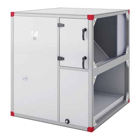
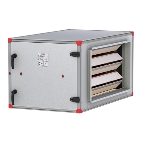
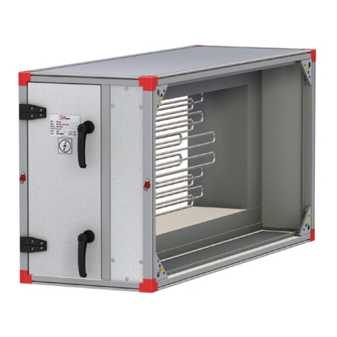
IV Produkt Flexomix 060 Troubleshooting guide

Continuous product development at IV Produkt may give rise to specification changes without notice.
Flexomix 060-950
DU11.F.081008.01GB
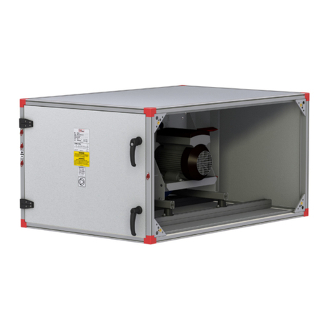
Fan Section (code EFA-FD/FR)
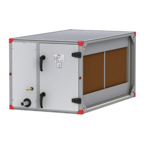
The EFA-FD/FR fan section is a unit section with
built-in fan with vertical outlet for use as a supply air
or extract air fan in ventilation systems together with
other functional sections in the Flexomix series.
Design
• EFA-FD with direct-driven fan (code ELFD).
The direct-driven fan is supplied with any of the
following types of motor:
- Motor including mounted frequency inverter.
- Motor to efficiency class eff1, for connection
to an external frequency inverter.
- Motor to efficiency class eff2, for connection
to an external frequency inverter.
• EFA-FR with belt-driven fan (code ELFR).
The belt-driven fan is available in two versions:
- ELFR-FB belt-driven centrifugal fan with,
casing, forward-curved blades.
- ELFR-BB belt-driven centrifugal fan with,
casing, backward-curved blades (sizes 150-950).
• To facilitate servicing, the fan and motor unit are
withdrawable from the casing.
• To adequately cool the motor, the air tempera-
ture should not exceed 50 ˚C.
• The fan and motor are very effectively vibration-
isolated from the casing with a vibration attenu-
ated outlet spigot and rubber mountings sized
to suit the fan’s operating conditions.
Normal resonance frequency is 7–10 Hz.
• The standard outlet of the fan section is
equipped with an end connection.
• The design of some of the components in the
fan system do not conform to corrosion resist-
ance class C4.
Other information is available under the Functional
Fittings tab, Direct-driven Fan (code ELFD) and Belt-
driven Fan (code ELFR).
Configuration EFA-FD
ELFD-060 – 950
310V 320V
310H 320H
210V 220V
210H 220H
210V 210H
310V 310H
ELFR-060 – 190-FB, ELFR-150 – 190-BB
Configuration EFA-FR
ELFR-060 – 950-FB, ELFR-150 – 950-BB
ELFD-060 – 190

Continuous product development at IV Produkt may give rise to specification changes without notice.
Flexomix 060-950
DU11.F.081008.01GB
Accessories for the fan section
Outlet:
• Connection frame, small (code MIET-AF-01-a).
For fan section EFA-FR with belt-driven fan
(code ELFR).
• Connection frame, large (code EMMT-02-a-1)
• Flexible connection, small (code MIET-AF-02-a).
For fan section EFA-FR with belt-driven fan
(code ELFR)
• Flexible connection, large (code EMMT-03-a-1)
Inlet:
• Connection frame, large (code EMMT-02-a-1)
• Connection frame, maximal (code EMMT-02-a-2)
See also section: Accessories.
Accessories for the EFA-FD
• Steel spring anti vibration mountings (sizes
360−950)
(code MIET-FD-03-a-d)
• Flow meter, manometer type
(code MIET-AF-09-d-DD)
• Flow meter, electronic (code MIET-AF-10)
See also section: Accessories.
Accessories for the EFA-FR
• Steel spring anti vibration mountings (sizes
150–600)
(code MIET-AF-03-a)
• Measurement tappings for ow meter excl. meter
(for ELFR-FB), (code MIET-AF-08-d-FB)
• Flow meter, manometer type (for ELFR-FB),
(code MIET-AF-09-d-FB)
• Flow meter, manometer type (for ELFR-BB),
(code MIET-AF-09-d-BB)
• Flow meter, electronic (code MIET-AF-10)
See also section: Accessories.

Continuous product development at IV Produkt may give rise to specification changes without notice.
Flexomix 060-950
DU11.F.081008.01GB
Dimensions and Weights
EFA-FD Fan section with ELFD fan
B H
L
CE
D A
Size
-aaa-
Impeller
size
-bbb-
Dimensions (mm) Total wgt.
(kg)* incl. max
motor
Max motor
size to IECL B H A C D E
060 025 630 850 440 500 300 175 165 65 71
100 028 630 980 505 700 300 140 205 80 80
150 035 780 1080 695 800 500 140 100 120 90
190 040 930 1360 695 1000 500 180 250 160 100
240 050 930 1360 805 1000 600 180 100 180 100
300 050 930 1580 805 1200 600 190 100 195 100
360 050 1080 1580 990 1200 800 190 100 225 100
360 056 1080 1580 990 1200 800 190 100 240 112
480 056 1230 1950 990 1400 800 275 100 250 100
480 063 1230 1950 990 1400 800 275 100 340 132
600 063 1230 2160 1095 1600 800 280 100 350 132
600 071 1380 2160 1095 1600 800 280 100 375 132
740 071 1420 2480 1240 2000 900 240 170 475 132
740 080 1570 2480 1240 2000 900 240 170 560 160
750 071 1420 2020 1370 1600 1000 210 50 455 132
750 080 1570 2020 1370 1600 1000 210 120 540 160
850 071 1420 2560 1370 2200 1000 180 50 505 132
850 080 1570 2560 1370 2200 1000 180 120 595 160
950 080 1570 2020 1660 1600 1200 210 50 575 160
950 090 1870 2020 1660 1600 1200 210 315 790 200
* The specified weight refers to a casing with standard insulation. For calculating the weight of casings with insulation to
re resistance class EI30, use the IV Produkt Designer product selection software.

Continuous product development at IV Produkt may give rise to specification changes without notice.
Flexomix 060-950
DU11.F.081008.01GB
Dimensions and Weights
EFA-FR fan section with ELFR fan
EC
A
B
AD
H
L
Size
-aaa-
Impeller
size
-bbb-
Dimensions (mm)
Total wgt. (kg)*
incl. max motor Max
motor
size to
IEC
L B H A C D E
V.210 & 310
E
V.220 & 320 ELFR-FB ELFR-BB
060 016 630 850 440 230 230 380 80 320 65 – 80
100 020 630 980 505 280 280 480 65 285 100 – 100
150 028 780 1080 695 385 385 490 65 330 135 140 112
190 028 930 1360 695 385 385 700 65 480 155 160 112
240 035 930 1360 805 475 475 550 75 380 220 225 132
300 035 930 1580 805 475 475 730 75 380 235 240 132
360 040 1230 1580 990 530 530 730 95 605 280 285 132
480 045 1230 1950 990 570 570 780 210 450 385 390 160
600 050 1230 2160 1095 640 640 780 255 335 435 445 160
740 050 1420 2480 1240 640 640 920 424 356 510 515 160
740 056 1570 2480 1240 720 720 880 130 719 575 585 180M
750 056 1570 2020 1370 720 720 899 130 719 555 565 180M
750 063 2020 2020 1370 806 806 607 143 1070 615 635 180
850 056 1570 2560 1370 720 720 920 130 719 600 610 180M
850 063 1720 2560 1370 806 806 877 131 782 625 645 180M
950 063 2020 2020 1660 806 806 607 144 1070 645 665 180
950 071 2170 2020 1660 903 903 558 233 1033 705 715 180
* The specified weight refers to a casing with standard insulation. For calculating the weight of casings with insulation to
re resistance class EI30, use the IV Produkt Designer product selection software.

Continuous product development at IV Produkt may give rise to specification changes without notice.
Flexomix 060-950
DU11.F.081008.01GB
Outlet connection frame, dimensions
CE
D A
EC
AD
For EFA-FD fan section For EFA-FR fan section
For inlet connection frames, see the EMMT-02.
Connection frame for EFA-FR fan sections
Size
-aaa-
Impeller
size
-bbb-
Small frame, MIET-AF-01, dimensions (mm) Large frame, EMMT-02, dimensions (mm)
A C D E
V.210 & 310
E
V.220 & 320 A C D E
V.210 & 310
E
V.220 & 320
060 016 300 300 345 65 265 500 300 175 65 265
100 020 300 300 470 65 265 700 300 140 65 265
150 028 500 500 430 65 215 800 500 140 65 215
190 028 500 500 640 65 365 1000 500 180 65 365
240 035 600 600 485 65 265 1000 600 180 65 265
300 035 600 600 665 65 265 1200 600 190 65 265
360 040 800 800 595 65 365 1200 800 190 65 365
480 045 800 800 665 200 230 1400 800 275 200 230
600 050 800 800 665 200 230 1600 800 280 200 230
740 050 900 900 790 170 355 2000 900 240 170 355
740 056 900 900 790 130 540 2000 900 240 130 540
750 056 1000 1000 760 130 440 1600 1000 210 130 440
750 063 1000 1000 510 140 875 1600 1000 210 140 875
850 056 1000 1000 780 130 440 2200 1000 180 130 440
850 063 1000 1000 780 130 590 2200 1000 180 130 590
950 063 1200 1200 410 140 675 1600 1200 210 140 675
950 071 1200 1200 410 230 735 1600 1200 210 230 735
Connection frame for EFA-FD fan sections
Size
-aaa-
Impeller
size
-bbb-
Large frame, EMMT-02, dimensions (mm)
A C D E
060 016 500 300 175 165
100 020 700 300 140 205
150 028 800 500 140 100
190 028 1000 500 180 250
240 035 1000 600 180 100
300 035 1200 600 190 100
360 040 1200 800 190 100
480 045 1400 800 275 100
600 050 1600 800 280 100
740 050 2000 900 240 170
740 056 2000 900 240 170
750 056 1600 1000 210 50
750 063 1600 1000 210 120
850 056 2200 1000 180 50
850 063 2200 1000 180 120
950 063 1600 1200 210 50
950 071 1600 1200 210 315

Continuous product development at IV Produkt may give rise to specification changes without notice.
Flexomix 060-950
DU11.F.081008.01GB
Operation and Maintenance
Instructions
Fan
General
The function of the fan is to transport air through the system,
i.e. the fan must overcome the air stream resistance present
in air diffusers and grilles, the ducting and the air handling
unit.
The fan speed is adjusted to provide the correct airow. If
the fan generates a lower airow, this may disturb ventilation
system performance.
If the supply airow is too low, there will be imbalance in
the system and this may cause draught problems. If the
ventilation capacity is too low, this may contribute to poor
room climate. If the extract airow is too low, poor ventila-
tion capacity will result. Imbalance can also lead to damp air
being pressed out into the building structure. An excessively
low extract airow causes increased power consumption if
a means of heat recovery is installed.
The reason why the fan impels too little air may be that the
v-belts are slipping. This may also be due to the effect of
dust deposits on the impeller blades.
If a centrifugal fan rotates in the wrong direction, the air will
ow in the correct direction but with reduced capacity. The
direction of fan rotation may have been changed as a result
of electrical installations. The direction of rotation should
therefore be checked.
Measures
N.B.! Before beginning work, switch off the air handling
unit from its switch and then turn the safety isolating
switch to the 0 position.
If the unit has double motors, there may be two switches.
1. Fan
What to check
Check that the fan impeller rotates easily, is in balance and
does not vibrate, and that the impellers are securely seated
on their shafts and that they have not shifted sideways toward
the inlet cones. Imbalance may be due to dust deposits on
or damage to the impeller blades.
Check by listening to hear whether any damage has arisen
in the bearings. Place a screwdriver, or the like, against the
bearing housing and listen with your ear against the screw-
driver handle. Normally you should hear only a humming
sound. If you hear a squeaking sound, the bearings need to
be lubricated. A scraping sound indicates that foreign par-
ticles have penetrated the bearing. A regular metallic noise
indicates that the bearing is damaged. In both these cases
the bearings should be replaced by new ones.
The fan impeller, bearing housing and motors are mounted on
a vibration-isolated base plate with anti-vibration mountings.
Check that the mountings are firmly secured and are intact.
Inspect the safety guards, exible connection, mounting
bolts and suspension devices, anti-vibration mountings and
base frame/stand.
Check that the impellers are clean, free of dust deposits.
Check tht the belt pulley mounting bolts are tight.
Cleaning
Wipe the fan impeller blades clean to remove possible dust
deposits. For this, you can use a mixture of Toluene and
denatured alcohol (2:1) or white spirit if required. Do not use
kerosene since it can cause rust to form on surfaces.
Then vacuum clean the air handling unit to prevent dust from being
discharged out into the duct system.
Clean the fan casing in the same way as the impellers.
Check that the enclosures and inlet cones are correctly secured.
Lubrication
If the fan bearing blocks are fitted with lubricators, lubricate
if required with SKF ALFA LUBE LG MT2 grease. In other
cases, the bearings are permanently lubricated and normally
do not require additional lubrication.
2. Belt Drive
Inspection
Check that the drive belts are not worn, broken, dried out
or damaged in any way. If the belts are damaged, they must
be replaced. If more than one belt must be replaced, you
must replace all the belts. Check that the belts are correctly
tensioned. Excessive tensioning can cause the bearings to
overheat and can overload the motor. Too loose tension will
cause the belts to slip and become quickly worn.
To replace or tension the belts
Tension the belts by moving the motor by means of the ten-
sioning bolts of the motor base plate. Do not force the belts
over the pulley, first release the tensioning bolts.
When changing belts, check that the pulley grooves are not
worn.
Use a ruler to check that the belt pulleys are parallel and that
their grooves are in alignment, see Fig 2.
Note that new belts should be re-tensioned after about
14 days.
Fig. 2
Continuous product development at IV Produkt may give rise to specification changes without notice.
Flexomix 060-950
DU11.F.081008.01GB
To adjust belt tension
To tension Poly-V belts (Ribbed belts)
Break-in
Poly-V belts must be correctly tensioned to achieve the best
useful life. Insufficient or excessive belt tension will shorten,
the belts’ useful life. We recommend the stretching method
which is simple and does not require special tools.
1. Lay the belt in the pulley grooves without tensioning
them.
2. Draw two lines across the backside at a distance of ap-
prox. 80% of the distance between the centres (or one
metre if the distance between the centres is long).
3. Increase the distance between the two lines by 0.5 to
0.75% by tensioning the belts (provides 5 to 7.5 mm at
a distance of 1000 mm between the shaft centres).
4. Operate the fan under load for approx. 10 minutes.
5. Check the belt tension by measuring the distance be-
tween the lines and adjust if necessary.
To adjust narrow V-belt tension
Breaking-in
New belts should be tensioned so that the necessary deec-
tion force (see Fig. 3) corresponds so much as possible to
the higher table value P in the table below.
Check the belt tension after 50 hours of operation.
80% of the natural belt stretching occurs within the first 15
hours of operation.
Check correct belt tension as follows:
1. Measure the distance between the shaft centres (A)
2. Measure the force required to achieve 16 mm belt de-
ection, reckoned per metre distance between the shaft
centres, perpendicular to the direction of belt movement and
approximately in the middle between the belt pulleys.
3. Increase the belt tension if the force is less than P in the
table or vice versa.
Correct belt tension can be checked as follows:
1. Measure the distance between the shaft centres.
2. Measure the force required to achieve 16 mm belt deec-
1000 mm
1007,5 mm
Tensioning distance for Poly-V belts
Distance between the marks
Before tensioning, After tensioning, mm
mm min max
100
150
200
250
300
350
400
450
500
600
700
800
900
1000
100.5
150.8
201.0
251.3
301.5
351.8
402.0
452.3
502.5
603.0
703.5
804.0
904.5
1005.0
100.8
151.1
201.5
251.9
302.3
352.6
403.0
453.4
503.8
604.5
705.3
806.0
906.8
1007.5
Belt profile
Deection P for a rise of
16 mm/m distance between shafts
Small pulley
diameter, dy
P Newton (N)
SPZ 67-95
100-140
10-15
12-20
SPB 160-224
236-315
35-50
50-65
SPC 224-355
375-560
60-90
90-120
tion, distance between the shaft centres, perpendicular
to the direction of belt movement and approximately in the
middle between the belt pulleys.
3. Increase the belt tension if the force is less than P in the
table or vice versa.
4. Recommended belt tensioning: 0.8 × Pmax.
3. Motor
f) Inspection
Listen to the bearings. If the bearing is OK you’ll hear a slight
humming. A squeak indicates that the bearing has too little
lubrication. A scraping or thumping sound indicates that the
balls or their races are damaged. Damaged bearing must be
replaced.
Check that the motor mounts are intact and that the mounting
bolts are tightened.
g) Cleaning
Keep the motor clean and free from dust, dirt and oil. Wipe with
a cloth. Use white spirit to remove hard-to-remove dirt.
Thick layers of dirt may cause internal overheating if they inhibit
cooling of the stator.
h) Lubrication
Motors equipped with lubricators should be lubricated once
every 750th service hour. Otherwise no lubrication other than
packing in bearings, whenever replacing bearings. Suitable
grease: SKF C65.

Continuous product development at IV Produkt may give rise to specification changes without notice.
Flexomix 060-950
DU11.F.081008.01GB
Fan
Fan unit
What to check
1. Back off the bolts, item A, and withdraw the fan
units (fan and motor are mounted on rails).
2. Check that the impellers rotate easily, are in balance
and do not vibrate. Imbalance may be due to dust
deposits or damages to the impeller blades.
3. Check that the impellers are well secured on their
shafts and that they have not shifted sideways to-
ward the inlet cones.
4. Fan and motor mounted on a stand are mounted
on rubber anti-vibration mountings. Check that the
mountings are secured and are intact.
5. Check the mounting bolts and the suspension de-
vices and stand.
6. Check that the impellers are clean and free of de-
posits of dust particles.
7. Refit the fan units.
8. Check the airflows by measuring Δp in the connec-
tions for flow measurement. Δp is used for obtaining
the airflow in a chart on the unit. Read the pressure
difference Δp on the measurement tube. Plot Δp in
the chart on the air handling unit, to the relevant unit
size and read the flow.
Cleaning
1. Follow items 1-6 under What to check.
2. Wipe the impeller blades clean to remove possible
dust deposits. Use an environment-friendly degreas-
ing agent. You should not use kerosene since this is
likely to cause rust.
3. The vacuum clean in a way that the dust will not be
blown out into the duct system.
4. Clean other parts in the same way as the impeller.
Check that the inlet cones are secured in place.
5. Follow items 7-8 under What to check.
A
Motor
What to check
1. Follow items 1-6 under Fan, What to check.
2. Check that the motor mounts are intact and that the
mounting bolts have been tightened.
3. Listen to the bearings. If the bearings are OK you’ll
hear a humming sound. A scraping or thumping
sound may indicate that the bearings are damaged.
Servicing is then required.
4. Follow items 7-8 under Fan, What to check.
Cleaning
Follow items 1-6 under Fan, What to check.
Keep the motors and control units free from dust, dirt and
oil. Clean surfaces with a cloth. If surfaces are heavily
fouled, use an environment-friendly degreasing agent as a
solvent, for instance. Thick layers of dirt may cause internal
overheating if they inhibit cooling of the stator.
Follow items 7-8 under Fan, What to check.
In the event of an alarm initiated from a motor with built-in
frequency inverter, reset the frequency inverter by de-
energizing the motor for at least 45 seconds. Check the
voltage and that the air handling unit is correctly installed.
Then restart the motor.
This manual suits for next models
10
Table of contents
Other IV Produkt Fan manuals

IV Produkt
IV Produkt Flexomix MIE-ID Installation guide

IV Produkt
IV Produkt Flexomix MIE-EL Installation guide

IV Produkt
IV Produkt Flexomix EXP Installation guide

IV Produkt
IV Produkt Flexomix MIE-FD User manual

IV Produkt
IV Produkt Flexomix MIE-EF Installation guide

IV Produkt
IV Produkt Envistar Top Series Installation guide
Popular Fan manuals by other brands

Progress Lighting
Progress Lighting AirPro P250040 installation manual

Exhausto
Exhausto CX3000 ASSEMBLY, INSTALLATION & MAINTENANCE INSTRUCTIONS

Casablanca
Casablanca Bella Bellatm Bella Ceiling Fan owner's manual

cecotec
cecotec ENERGYSILENCE 8090 SKYLINE instruction manual

CFM
CFM HRV-0904 Specifications

Craftmade
Craftmade Axel installation guide