Continuous product development at IV Produkt may give rise to specification changes without notice.
Flexomix 060-950
DU14.F.110907.05.EN
Inspection
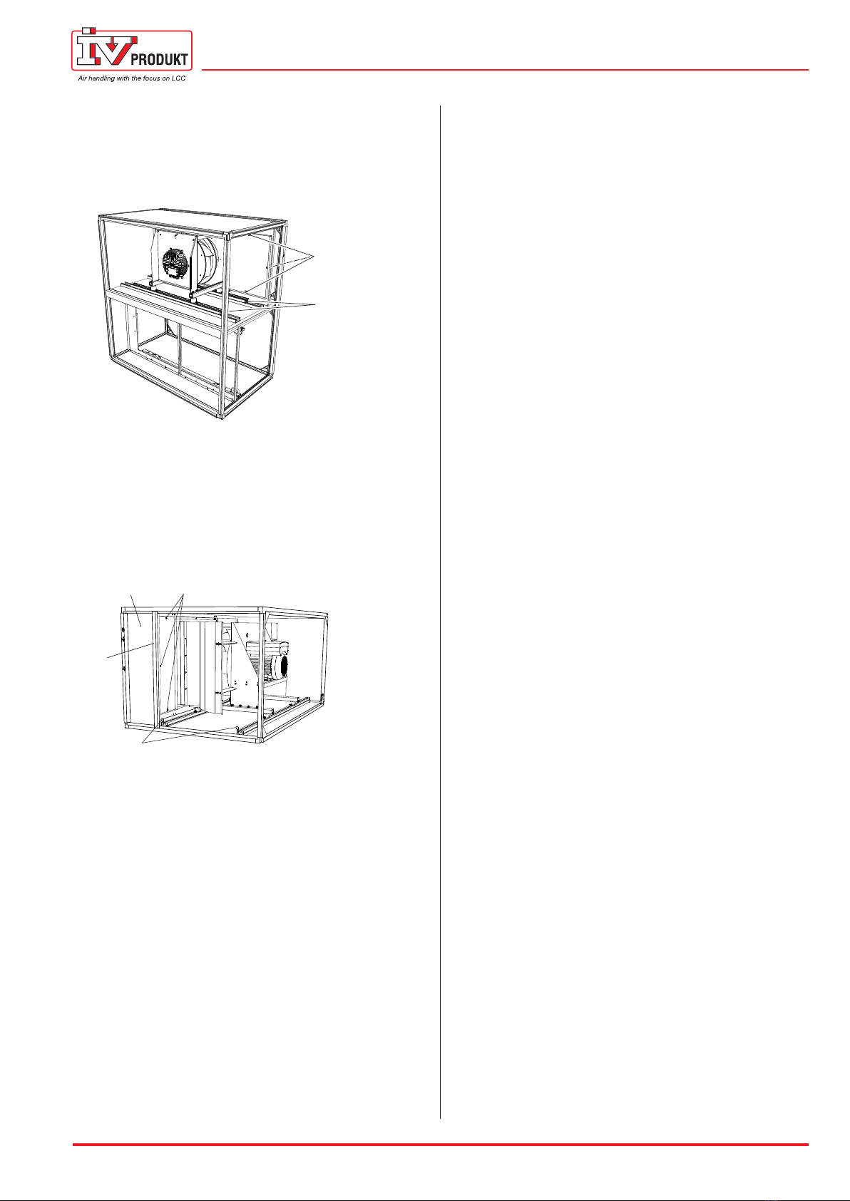
1. Sizes 060–360:
Removethescrews(item1)andthepins/screws
(item 2) and withdraw the fan units (fan and motor
are mounted on slide rails).
2
1
Example fan unit sizes 060–360
Sizes 480–600:
Accesstothefanisnormallyviatheinspection
door.Ifrequired,removethecentreuprightbeam
(item 1) and fixed cover (item 2), remove the screws
(item3)andthepins(item4)andwithdrawthefan
units (fan and motor are mounted on slide rails).
4
1
23
Example fan unit sizes 480–600
Sizes 740-950:
Thefansarerigidlymountedandcanbeaccessed
through the inspection door/doors.
2. Checkthattheimpellerrotateseasily,isinbalance
andisnotvibrating.Checkalsothattheimpeller
iscleanfromanyaccumulationofparticles.Imbal-
ancemaybeduetoacoatingordamagetothe
impellerblades.
3. Listentothesoundfromthemotorbearings.Ifthe
bearingsareingoodconditionyouwillhearaslight
purringsound.Ascrapingorpoundingsoundmay
meanthatthebearingsaredamagedandservicing
is then required.
4. Check that the impellers firmly mounted and that
they have not shifted sideways toward the inlet
cone.
5. Thefanimpellerandmotoraremountedonabase
framefittedwithrubberanti-vibrationmountings.
Checkthattheanti-vibrationmountingsarefirmly
mounted and are intact.
6. Checktheconditionofthemountingscrews,the
suspensiondevicesandthebaseframe.
7. Check that the gaskets on the connection plates
around the connection opening are intact and are
firmly fitted.
8. Checkthatthemeasurementtubesarefirmlyfitted
to their relevant measurement tapping.
9. Reassemblethefanunits.
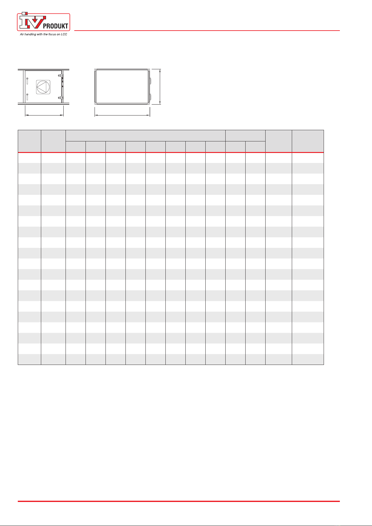
10.ChecktheairflowsbymeasuringΔp in the connec-
tionsforflowmeasurement.UsetheAHU’sflowla-
belandreadwhichflowcorrespondstomeasured
Δp.
Cleaning
1. Follow item 1-8 under Inspection.
2. Wipethefanimpellerbladestoremoveanycoat-
ings. Use an environment-friendly degreasing
agent.
3. Theexternalsurfacesofthemotorshouldbekept
clean.Removeanydust,dirtandoil.Cleanwith
a dry cloth. If they are severely fouled, use an
environment-friendly degreasing agent. The motor
is likely to overheat if thick layers of dirt prevent air
from entering the motor to cool the stator structure.
4. Vacuum clean inside the air handling unit so that
particleswillnotbeblownoutintotheductsystem.
5. Clean the other parts in the same way as the impel-
ler. Check that the inlet cones are securely mount-
ed.
6. Followitem9underInspection.
To reset the overheating protection
(EC motors)
1. Switchoffthepowersupplytothefanmotor.
2. Wait at least 20 sec. after the impeller has finished
rotating.
3. Switchonthepowersupplytothefanmotor.