Table of Contents
1 Safety precautions
1.1 Lockable safety switch .............................................................................4
1.2 Inspection doors ...........................................................................................4
1.3 Electrical connection ..................................................................................4
1.4 Compressor section ...................................................................................4
2 General
2.1 Intended use ....................................................................................................5
2.2 Manufacturer ....................................................................................................5
2.3 Designations ....................................................................................................5
2.4 CE marking and EU Declaration of Conformity ......................6
2.5 Maintenance .....................................................................................................6
2.6 Handling of refrigerant ..............................................................................6
2.7 Extended warranty .......................................................................................7
2.8 Spare parts ........................................................................................................7
2.9 Dismantling and decommissioning .................................................7
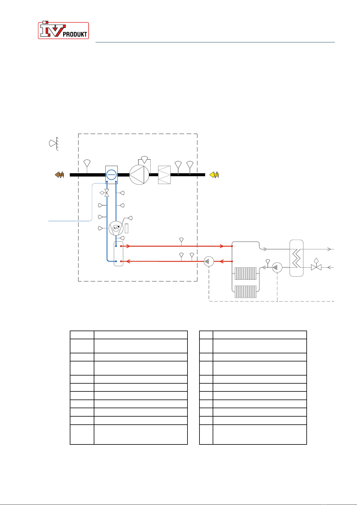
3 Technical description
3.1 Design ...................................................................................................................8
3.2 Function ...............................................................................................................9
4 Wiring instructions and fuse protection
4.1 Wiring diagrams ..........................................................................................12
4.2 Recommended fuse protection and power supply ..........12
4.3 Wiring instructions ....................................................................................13
5 Operation
5.1 Commissioning ...........................................................................................14
5.2 Commissioning combustion gas bypass .................................15
6 Maintenance instructions
6.1 Service schedule ........................................................................................16
6.2 Filters (code ELEF) ....................................................................................17
6.3 Fan unit (code ENF) ..................................................................................20
6.4 Damper (code EMT-01) .........................................................................23
6.5 Combustion gas bypass (code EHP-B) .....................................24
6.6 Sound attenuator (code EMT-02) ...................................................25
6.7 Compressor section (code EHP-C) ..............................................26
7 Troubleshooting
7.1 Troubleshooting in the event of an alarm .................................28
7.2 Troubleshooting via symptoms and status message ......29
7.3 Alarm reset .....................................................................................................30