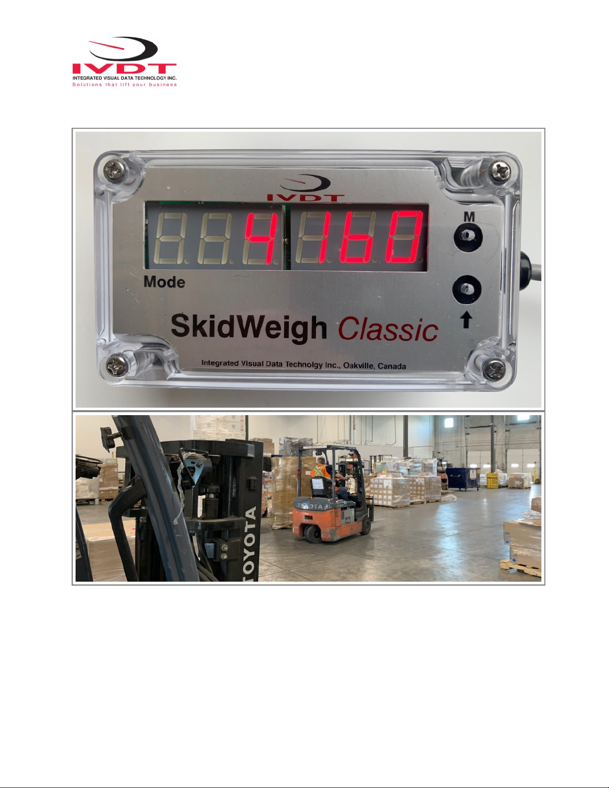
SkidWeigh “weighing cycle” will be automatically activated every time load is lifted just above the ground. The
increase in pressure is converted in an electronic signal at the sample rate of 16000 readings per session which is
converted into a load weight reading utilizing proprietary software algorithm.
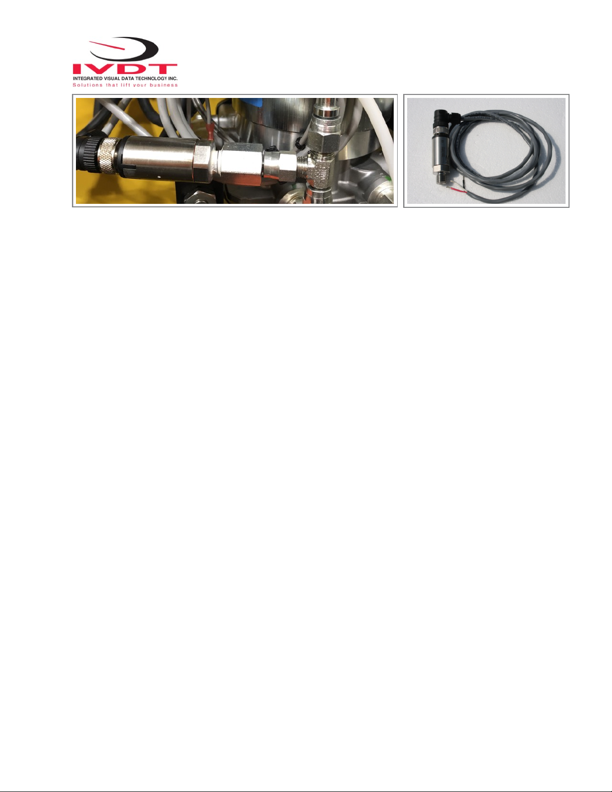
Pressure transducer installation
The pressure transducer must be installed in the lifting hydraulic line between the lift control valve and lift
cylinder(s). Mount a T-piece in hydraulic line. In some cases you can install the pressure transducer in the flow
divider, drilling and tapping for 1/4”-18 NPT male in spare plug (single or double mast configuration) or in the body of
the flow divider. In some cases you can drill and tap on “larger elbow” if available in the hydraulic lifting circuit found
in vehicles with larger hoses accommodating larger vehicle lifting capacities.
Pressure transducer installation precautions
Before installation of the pressure transducer the hydraulic lift circuit must be pressure free.
There are two ways to do that:
1. Place the forks on the ground in their lowest position and make the hydraulic system pressure free by tilting the
mast forward. The chain(s) should be slack.
2. Lift the forks and position them on the top of a supporting fixture. Start lowering the lifting cylinder into its lowest
position. Be sure that chain(s) are slack.
Make sure that that installed pressure transducer will not touch any moving parts or assembly of the vehicle while in
normal operation. Pressure transducer has 1/4”-18 NPT male thread. Use
thread seal to ensure tight fit.
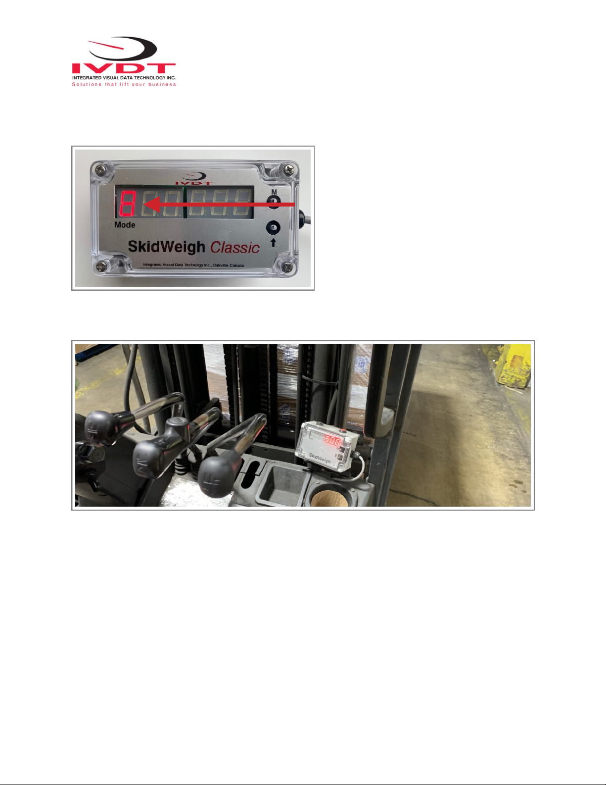
Selecting the mounting location for digital indicator
Use the mounting flange and fasten digital indicator on the vehicle dashboard or
side railing preferably on the right hand side.There are many examples of
mounting locations that will depend on the vehicle model. However, additional
mounting items such as a flat brackets may be needed to help secure the unit to
upper right corner of the guard or side railing.
Choose the correct location and make sure that:
- Indicator is visible and within reach of the operator
- Location so that operator does not hit a head
Electrical Connections
All SkidWeigh systems operate from 12 to 55 VDC.
(For voltages above 55 VDC order voltage convertor Part No. VC160)
-Orange Wire (+) Ignition switch On position
- Brown Wire (-) Battery negative
- Red Wire, connect to RED wire of the pressure transducer cable
- Black Wire, connect to BLACK wire of the pressure transducer cable
- White Wire, connect to WHITE wire of the pressure transducer cable
Optional Dry Relay Contacts for External Overload Alert (Contact current rating, max. 1A) -
Yellow Wire N.C. - Blue Wire N/O. - Green Wire Common