manuals.online logo
Brands
  1. Home
  2. •
  3. Brands
  4. •
  5. Ives
  6. •
  7. Indoor Furnishing
  8. •
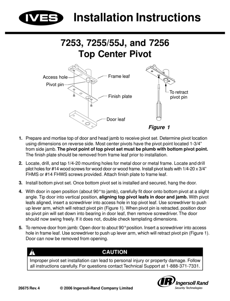
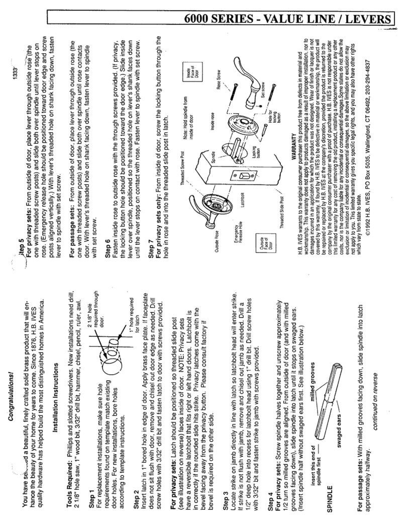
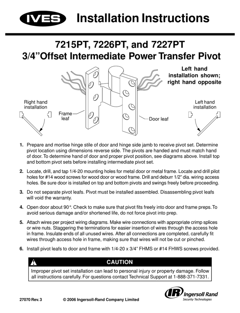
  9. Ives 611 Series User manual

Ives 611 Series User manual

829172-00(0) © 2006 Ingersoll-Rand Company Limited
611 and 711 Series Swing Clear Continuous Hinges
Mark frame hole locations.
1
Mount hinge to door.
2
Mount door to frame
3
Check for proper operation.
4
Determine TOP of hinge using
door and frame as guide.
Open hinge and place frame leaf
flat against surface of frame leaving
1/8 gap between top of hinge and
bottom of frame header, and edge
of hinge frame leaf flush with inside
edge of frame.
ark hole locations on frame using
center punch. A center punch mark is
required to start self drilling screws accurately.
DO NOT install hinge to frame at this time.
Place door leaf of hinge against hinge
edge of door so that top of hinge is
flush with top of door and edge guard
is flush with inside face of door.
With hinge held firmly in place, use
#10 x 1/2 self drilling screws to fasten
leaf to metal door, or #10 x 1 wood
screws to fasten leaf to wood door.
Note: Fasten top screw first, and
bottom most screw second, making
sure hinge is aligned correctly.
ALL HOLE LOCATIONS ON HINGE LEAF MUST BE FASTENED TO
DOOR FOR PROPER OPERATION. FAILURE TO INSTALL ALL
FASTENERS WILL VOID WARRANTY AND UL FIRE LABEL LISTINGS.
Installation Instructions
Note: Before proceeding, check to be sure that hinge is proper size. Height of hinge should be 7/8
LESS than opening height. See other side of page for cutting instructions.
A.
B.
C.
A.
B.
1/8
Flush
ove door into opening and align
mounting holes in frame leaf of hinge
with marks on frame made in step 1
above. Note: An angle block, jack or
shims will be helpful in positioning
the door properly.
With hinge and door held firmly and
accurately in place, use #10 x 1/2
self drilling screws to fasten
frame leaf of hinge to frame
in marked locations.
A.
B.
ALL HOLE LOCATIONS ON HINGE LEAF MUST BE FASTENED TO
FRAME FOR PROPER OPERATION. FAILURE TO INSTALL ALL
FASTENERS WILL VOID WARRANTY AND UL FIRE LABEL LISTINGS.
Close door and check for
proper operation and
clearances. There should be
1/8 clearance between the
top of the door and the bottom
of the frame header, and 5/32
clearance between the frame
and edge of the door when the
door is closed. Adjustments
can be made by shimming
frame or door leaf of hinge.
A.
5/32
1/8
Door Frame
Flush with
top of door
Door
Flush
829172-00
To bottom of frame
!CAUTION
Please follow the installation instructions carefully. Not doing so may
result in improper installation and void the manufacturers guarantee.
INSTALLATION NOTES
No reinforcing is necessary except on heavy doors. Reinforcement and
rivet nuts are required in the frame and door when door weight exceeds
300 pounds. aximum door weight is 600 pounds.
If the mullion is between the doors, treat as a single door installation. If
the mullion is behind the doors, treat as a double door installation.
Reinforcing and Rivet Nuts:
Pairs of Doors with Mullions:
Page 2 o 2 829172-00(0)
Instructions for Cutting Hinge
Determine hinge height.
1
Mark hinge for cutting.
2
Cut hinge.
3
Shorten hinge pin 3/ .
4
Insert top and bottom tip.
5
easure height of opening
from finished floor to
underside of door frame
header.
Hinge height is height of
opening INUS 7/8.
Important Note:
6
Fold hinge so that cut line is visible.
Starting on barrel, cut through
entire hinge along line.
Debur all cut edges with file.
Use center punch or heavy gauge
nail on pin in short cut off portion of
hinge to remove hinge tip. SAVE
HINGE TIP for use in step 5.
Tap hinge pin back into barrel.
Tap hinge pin tips (retained from step 3 and 4) firmly
into top and bottom of barrel until shoulder sets
squarely on barrel.
NOT : Both tips UST BE INSTALLED to hold hinge
pin in position.
Determine which end of
hinge will be the TOP
using door and frame as
a guide.
Open hinge to expose
back of hinge (holes
are NOT countersunk).
easure hinge height
calculated in step 1
from top of hinge.
Using square, mark a line
on back of both hinge
leaves and the barrel.
Using center punch or heavy nail, tap on cut surface of
hinge pin to remove top hinge tip (save tip for step 5).
Expose 1 of hinge pin. easure and mark 3/4 from end
of pin.
DOUBLE CHECK EASURE ENT BEFORE CUTTING.
Cut pin at mark.
DOUBLE CHECK EASURE ENT BEFORE CUTTING!
NOT :
Cut end of hinge must be used as BOTTO OF HINGE ONLY!
If more than 6 is cut from bottom of hinge, additional
mounting holes will be required on bottom of hinge. Use cut
off piece of hinge to mark and prepare hole locations on
bottom of hinge.
Height of
opening
INUS 7/8
Opening
height
minus
7/8
Bottom
Cu ing line
A.
B.
A.
B.
C.
D.
A.
B.
C.
D.
A.
B.
C.
A.
B.
Save ip
3/4
Save tip
Top

This manual suits for next models

1

Other Ives Indoor Furnishing manuals

Ives 26 User manual

Ives

Ives 26 User manual

Ives Offset Intermediate Power Transfer Pivot... User manual

Ives

Ives Offset Intermediate Power Transfer Pivot... User manual

Ives 14 User manual

Ives

Ives 14 User manual

Ives Value Lines Lever 6000 User manual

Ives

Ives Value Lines Lever 6000 User manual

Ives VR900 User manual

Ives

Ives VR900 User manual

Ives 7259 User manual

Ives

Ives 7259 User manual

Ives Top Center Pivot 7255/55J User manual

Ives

Ives Top Center Pivot 7255/55J User manual

Popular Indoor Furnishing manuals by other brands

Sigel Glas-Magnetboard artverum Mounting and safety instructions

Sigel

Sigel Glas-Magnetboard artverum Mounting and safety instructions

Strictly Beds & Bunks Stockton Bunk Bed Assembly instructions

Strictly Beds & Bunks

Strictly Beds & Bunks Stockton Bunk Bed Assembly instructions

Core Products VG106 Assembly instructions

Core Products

Core Products VG106 Assembly instructions

overstock PP287157 Assembly instruction

overstock

overstock PP287157 Assembly instruction

fantastic furniture GEO 16 CUBE Assembly instructions

fantastic furniture

fantastic furniture GEO 16 CUBE Assembly instructions

Coaster 3393 Assembly instructions

Coaster

Coaster 3393 Assembly instructions

Allen + Roth SP4960 user manual

Allen + Roth

Allen + Roth SP4960 user manual

Silverline 968731 quick start guide

Silverline

Silverline 968731 quick start guide

Kettler T0251-0200S manual

Kettler

Kettler T0251-0200S manual

GALA MEBLE K02-G80K Assembly manual

GALA MEBLE

GALA MEBLE K02-G80K Assembly manual

Tresanti ODP40557-D908 manual

Tresanti

Tresanti ODP40557-D908 manual

Powell 723-018 Assembly instructions

Powell

Powell 723-018 Assembly instructions

CONFORAMA CADENZA W Assembling instructions

CONFORAMA

CONFORAMA CADENZA W Assembling instructions

BIG LOTS STORES SIDNEY 1513DR Assembly instructions

BIG LOTS STORES

BIG LOTS STORES SIDNEY 1513DR Assembly instructions

ALDI SOHL Furniture Jenna GLS19745 Assembly instructions

ALDI

ALDI SOHL Furniture Jenna GLS19745 Assembly instructions

Ovela HINDMARSH OVHINDMBWSA user guide

Ovela

Ovela HINDMARSH OVHINDMBWSA user guide

RSA Lighting QCT902ICMH specification

RSA Lighting

RSA Lighting QCT902ICMH specification

VonHaus 2500166 Assembly instructions

VonHaus

VonHaus 2500166 Assembly instructions

manuals.online logo
manuals.online logoBrands
  • About & Mission
  • Contact us
  • Privacy Policy
  • Terms and Conditions

Copyright 2025 Manuals.Online. All Rights Reserved.