TABLE
OF
CONTENTS
Cautions
on
Operations
..
SECTION
1
SPECIFICATIONS
.
1-1
GENERAL
1-2
SPECIFICATION
.
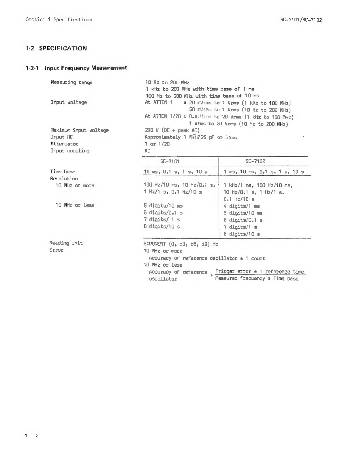
1-2-1
Frequency
Measurement
.
1-2-2
General
csccescceccceee
1-2-3
Physical
Characteristics
-3
ENVIRONMENTAL
CHARACTERISTICS
-4
ACCESSORIES
..eeeeesseseeee
1
1
SECTION
2
OPERATING
INFORMATION
..cccccscccccccccccscvccccssccsccscccsssssssecsssssssssssssceees
2-1
FRONT
PANEL
.....
2-1-1
Power
Supply
aa
2-1-2
Display
of
Measured
Results
2-1-3
Input
ceccceee
2-1-4
Measuring
Condition
Setting
2-2
REAR
PANEL
wesccccccccescccesece
.
2-3
DISPLAY
UNIT
sescsscseccccccccscscseces
2-4
HOW
TO
USE
THE
CARRYING
HANOLE
(STAND)
NNNNNNNNN
SECTION
3
MEASURING
PROCEOURES
3-1
POWER-ON
.
3-2
ON
RESET
.
3-3
MEASUREMENT
.
3-3-1
Frequency
Measurement
.
3-3-2
DIFF
Calculation
.
3-4
MEASUREMENT
USING
AN
EXTERNAL
REFERENCE
OSCILLATOR
3-5 USE
AS
THE
SECONDARY
FREQUENCY
STANDARD
UUUwnWwaww
SECTION
4
ADJUSTMENT
OF
REFERENCE
OSCILLATOR
sesseeeseeccccccccenccccecccencesssceassssssesessees
4-1
PREPARATION
FOR
ADJUSTMENT
...
4-1-1
Removing
the
Upper
Cover
.
4-1-2
External
Reference
Oscillator
.
4-2
ADJUSTMENT
PROCEDURE
«.sseeeeeeeeee
SECTION
5
SCHEMATIC
DIAGRAM
.
'
PEEUNNA=
'
OUFENNZA245
'
BE
ENN=AS5
'
Nese