IXSEA Octans 3000 User manual

Quick
G
Quick Start
Guide
Octans 3000
subsea gyrocompass and motion sensor

1
2010-06/MU/OCT 3kG4 /001 / Ed. B
FOREWORD
OCTANS 3000 QUICK START GUIDE
Objective
This guide describes how to install the OCTANS 3000, and the basic configurations required before beginning the positioning
Contents
OBJECTIVE...........................................................................................................................................................................................01
CONTENTS...........................................................................................................................................................................................01
CONVENTIONS.....................................................................................................................................................................................02
OCTANS 3000 SYSTEM OVERVIEW......................................................................................................................................................03
VERIFICATION OF PACK CONTENTS ...................................................................................................................................................03
STEP 1 - OCTANS 3000 GUIDED TOUR................................................................................................................................................04
STEP 2 - ONBOARD INSTALLATION......................................................................................................................................................18
STEP 3 - MORE.....................................................................................................................................................................................25
CUSTOMER SUPPORT..........................................................................................................................................................................28
IXSEA CONTACT...................................................................................................................................................................................29

22010-06/MU/OCT 3kG4 /001 / Ed. B 3
2010-06/MU/OCT 3kG4 /001 / Ed. B
The following conventions are used in this guide
The symbol leads you through nested menu items and/or dialog box options to a final action.
Example:
Logging Configure Logging Parameters means “Select Configure Logging Parameters option
from the Logging pull down menu”.
bold Bold text is used for items you must select or click in the software.
It is also used for the field names used into the dialog box.
Courier Text in this font denotes text or characters that you should enter from the keyboard, the proper
names of disk Drives, paths, directories, programs, functions, filenames and extensions.
italic
Italic text is the result of an action in the procedures.
CONVENTIONS OCTANS 3000 OVERVIEW
OCTANS 3000 is both a fiber-optic survey-grade gyrocompass and a Motion Reference Unit for Marine applications.
The core of OCTANS 3000 is a compact strap-down Inertial Measurement Unit (IMU) which contains three accelerome-
ters, three fiber-optic gyroscopes, and a real-time computer. This unit computer is a Digital Signal Processor (DSP) chip
enabling complex real-time computation.
The heading search algorithm has been designed by IXSEA. Heading and attitudes are computed whether the system is
in movement or not, and without an external reference point. Computation is based on (filtered) measurement of shifts
in local gravity as the Earth rotates. It involves angle integration using quaternion algebra, a heading search algorithm,
and Coriolis force correction for vessel speed.
The OCTANS 3000 system is used to deliver:
• True heading, roll, pitch
• Heave, surge, sway
• Rates of turn and accelerations
OCTANS 3000 is delivered with a powerful and easy-to-use WEB-based User Interface, which allows a complete confi-
guration.
VERIFICATION OF THE PACK CONTENTS
You will find in the shipping case a Packing List detailing all the items delivered. This packing has been completed and
checked by IXSEA shortly before shipment, and should match the contents of the pack you have received.
However, we recommend that you check the contents of the pack and the equipment immediately on receipt of your
OCTANS 3000 unit. Specifically, you should check that all the items referred to above are present on delivery and that
none has sustained damage.
If you observe any non-conformity or damage, please inform the carrier and IXSEA without delay by certified mail,
describing in detail the problem encountered.

42010-06/MU/OCT 3kG4 /001 / Ed. B 5
2010-06/MU/OCT 3kG4 /001 / Ed. B
STEP 1 - OCTANS 3000 GUIDED TOUR
Connecting OCTANS 3000 to PC and Mains
As soon as OCTANS 3000 is powered up, it starts its 5-minute alignment phase. During this alignment phase, heading
and attitude data are available, but have not reached full accuracy (see figure 1). Specified accuracy on heading, roll and
pitch is reached at the end of the 5 minutes long alignment phase. Heave initialization occurs at each OCTANS 3000
powering on or soft restart. It is performed in parallel with the OCTANS 3000 alignment phase, but it is time set to 5 addi-
tional minutes. During the heave initialization phase, the heave, surge and sway outputs have not reached full accuracy.
Heading
and Attitude
Motion sensing
System Status System init
/Alignment
System init
/Heave init System OK
No output Reliable
output
Reliable
output
Alignment phase Heave
initialisation
Full accuracy output
Full accuracy
output
time in mn0’ 1’ 5’ 10’
Figure 1 – OCTANS 3000 Starting Sequence (at powering-on or restart)
Warning: At any power supply outage, OCTANS 3000 restarts its initialization.

62010-06/MU/OCT 3kG4 /001 / Ed. B 7
2010-06/MU/OCT 3kG4 /001 / Ed. B
Launching the WEB-based User Interface
Required environment:
• The workstation must be equipped with one of the following Web browser:
Mozilla Firefox version 3.5 and higher
Chrome version 4 and higher
Safari version 4 and higher
Opera version 10 and higher
Internet Explorer version 7 and higher
• Flash Player version 10 (and higher) must be installed on the workstation to visualize the compass
• For the data logging: Java Runtime Environment 1.6 (and higher)
The Control Pages opens:
During the first seconds the IXSEA logo is flashing grey-blue indicating that the Web-based User Interface is loading
the internal configuration of OCTANS 3000. Then the logo turns blue, the alignment sequence of OCTANS 3000 begins.
Menu Bar
The menu is blue when selected
Compass area
Navigation data window: it displays
all data either computed by OCTANS
3000 or coming from GPS/log
Maintenance page: firmware
upgrades,system restarting,
support contact
Options page : language selec-
tion , day/night mode selection
Latitude and speed data
(manual or GPS/log inputs)
Heading, Roll, Pitch,
and Heave data
System status:
color and verbose display

82010-06/MU/OCT 3kG4 /001 / Ed. B 9
2010-06/MU/OCT 3kG4 /001 / Ed. B
WEB-Based User Interface - General Rules, Commands and Navigation
IXSEA logo handling
A click on the IXSEA logo opens the detailed status pop-up window and the compass disappears. This window summed-
up the status of: • The input ports
• The output ports
• The system
• The external sensors
You can close the pop-up by clicking either on the IXSEA logo or in the Status area.
Color Code
The color code applies for the indicators and text labels displayed in this pop-up window.
When a problem occurs, the color of the IXSEA logo changes and the detailed status pop-up automatically appears
showing immediately which equipment has raised the problem.
Table 1 – Color code definition
General Rules for Using Command Windows
The command windows allow you to display or modify OCTANS 3000 configuration parameters. At first delivery, these
parameters are set to default values. You have to modify them to fit your needs:
Scrolling list selection
• By selecting it directly in the scrolling list:
Note
you can also use the up arrow ([]) and down arrow ([]) keys to scroll in the list.
Tick box
• By selecting it by clicking in the dedicated box:
Color Definition
Grey inactivity
Flashing Grey/Blue System Configuration (during initialization for example)
Blue Activity, nominal operation
Orange Activity, warning
Red Activity, alarm

10 2010-06/MU/OCT 3kG4 /001 / Ed. B 11
2010-06/MU/OCT 3kG4 /001 / Ed. B
Text box
• By typing it in the dedicated area:
Note
you can also use the up arrow ([]) and down arrow ([]) keys to increase or decrease
the numerical values.
Incorrect value are immediately indicated by red color:
Expanding hidden area
In order to keep each web-based page as small as possible, only the main parameters are default
visible. You can expand the hidden area by clicking on its text label title:
OK/Cancel buttons
Each command page contains the same buttons, they appear as soon as a modification or a selection
has been made in the command page:
To validate the new configuration and store it in the OCTANS 3000 PROM.
To return to the previous entered values.
Other Button
On “mouse over” action, orange color may surround a button to indicate that the action performed
by clicking on the button has consequences.
Examples of such action:
• OCTANS 3000 restart (the alignment process is repeated)
• Reset to factory settings (the customized configuration is lost)

12 2010-06/MU/OCT 3kG4 /001 / Ed. B 13
2010-06/MU/OCT 3kG4 /001 / Ed. B
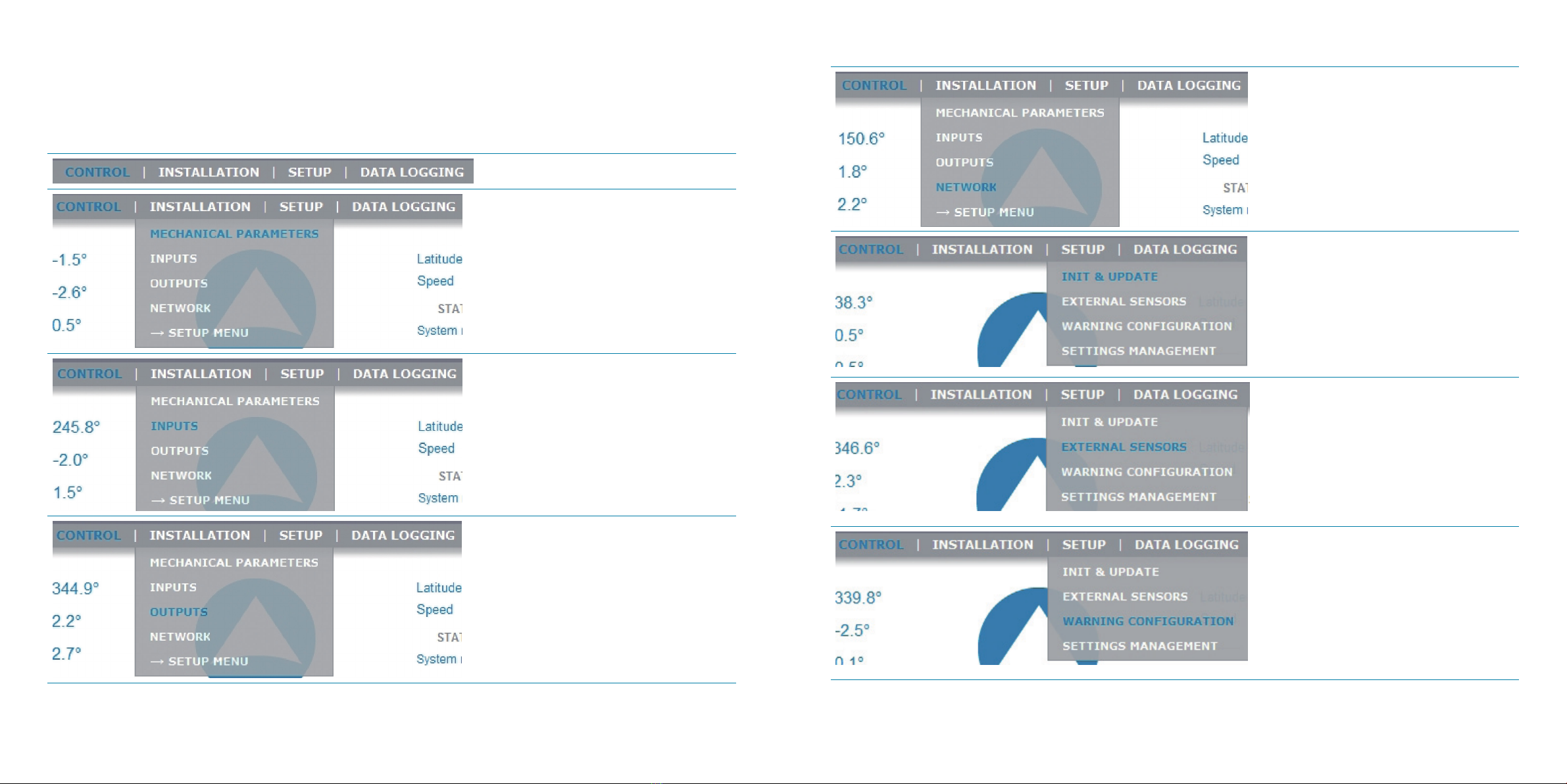
WEB-based User Interface - Menus and Options Overview
Find hereafter all the menus and options of the WEB-based User Interface and their uses
Menu /options Used to …
Define the OCTANS 3000 orientation, pos-
sible roll, pitch and heading misalign-
ments, primary and secondary lever arms
useful to compute the heave and position
for the output protocols that provide it
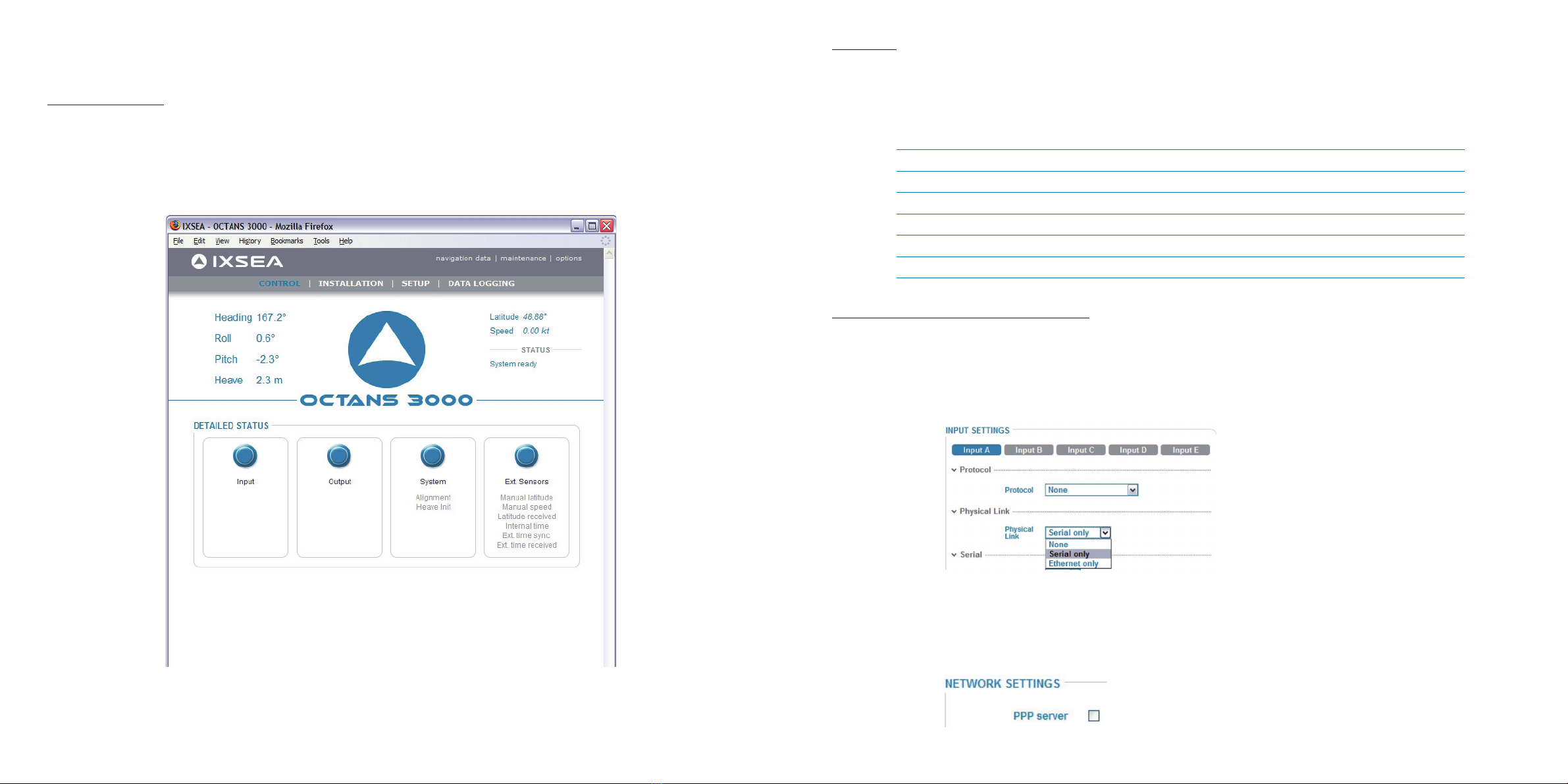
Define the inputs, the protocol used to
input the data, the serial (parity, baud rate,
standard (RS232 or RS422) and stop bit)or
Ethernet (transport layer, IP address, Port
number) parameters
Define the outputs, the protocol used to
output the data, the lever Arm to use, the
data rate or the input pulse to use to syn-
chronize the output data, the serial (parity,
baud rate, standard (RS232 or RS422) and
stop bit)or Ethernet (transport layer, IP ad-
dress, Port number) parameters, the pulse
output to output the envelop, the heave fil-
ter to use
Menu /options Used to …
Define the Network parameters for com-
munication through a serial ling (PPP op-
tion) or through Ethernet one (DHCP client
mode activation, OCTANS 3000 IP address
and Network mask to use
Enter the initial latitude and speed or to
update them
Define the parameters of
• The time synchronization (UTC); input
selection, pulse input selection for the PPS
signal, the protocol to use for the PPS si-
gnal
• The log: pulse input selection for the
speed synchronization signal, the protocol
to use for the synchronization signal, the
scale factor for the chosen protocol
To be informed in case of warning or error
for
• PPS synchronization loss
• Time synchronization loss
• External latitude synchronization loss
• External speed synchronization loss

14 2010-06/MU/OCT 3kG4 /001 / Ed. B 15
2010-06/MU/OCT 3kG4 /001 / Ed. B
Menu /options Used to …
To save /restore product settings
Log the data of the repeater output or of
any A to E output.
• Restart your OCTANS 3000 Unit
• Update the system: firmware, loader,
and/or WEB-Based User Interface versions
• Get OCTANS 3000 serial number and
WEB-based User Interface
• Contact IXSEA Support
Display all navigation data computed and
received by OCTANS 3000
• Choose the Web-based User Interface
language (English or French)
• Choose the display mode (night/day
mode)
Entering the Initial Latitude
All gyrocompasses, OCTANS 3000 included, are sensitive to the current latitude. However latitude needs to be updated
into OCTANS 3000 only if the ship changes latitude quite substantially. OCTANS 3000 has to know the latitude of its loca-
tion in order to find geographical North rapidly. If the latitude information input is incorrect, OCTANS 3000 will produce
an error.
IMPORTANT
OCTANS 3000 is delivered with a default latitude setting that corresponds to IXSEA's factory location. At first powe-
ring-on, without external GPS connected, OCTANS 3000 will start seeking north with this latitude input, which may be
quite different from the current OCTANS 3000 latitude.
Latitude has to be modified by the user. Once this modification is performed, it is recommended to save the current lati-
tude into OCTANS 3000 PROM and re-start the unit.
This procedure allows for the OCTANS 3000 to enter the correct latitude value as an input in the North finder algorithm as
soon as computation starts. OCTANS 3000 will then reach full accuracy after the 5 minutes alignment phase. Otherwise,
time for OCTANS 3000 stabilization will be increased due to the wrong initial latitude input when computation starts.
This procedure should be done whenever a unit is delivered from factory, or whenever a new firmware has been re-loa-
ded into the unit

16 2010-06/MU/OCT 3kG4 /001 / Ed. B 17
2010-06/MU/OCT 3kG4 /001 / Ed. B
Step 1:
Step 2:
Step 3:
Select INIT & UPDATE option of SETUP menu to open the INIT
& UPDATE page
Enter the correct value in the Latitude field
Click OK button to save the modification into OCTANS 3000 PROM
Step 4: Click on maintenance menu to open the maitenance page
Step 5: Click on Restart button to restart the OCTANS 3000 unit

18 2010-06/MU/OCT 3kG4 /001 / Ed. B 19
2010-06/MU/OCT 3kG4 /001 / Ed. B
STEP 2 - ONBOARD INSTALLATION
Mechanical Installation
OCTANS 3000 is installed using six M6 screws accessible from the top of the unit (see Figure 2).
Recommendations and Note
• Temperature in operation must be in the range -20 °C to 55 °C
• The dimensions of the OCTANS 3000 housing are ((l x Ø) in mm ):374 x 213. There must be enough place for the wire
way on the connector side of OCTANS 3000.
• The weight of OCTANS 3000 is 14.6 kg in air and 4.65 kg in water.
Figure 2 – Definition of OCTANS 3000 Reference Frame (X1,X2, X3) and P center of measurements
Electrical Connections
All OCTANS 3000 inputs/outputs are made using sealed connectors, SEACON plug type.
In the standard case described below, all connections are Ethernet ones.
• Power Supply: Use the 19-pin test cable for direct connection to the 24V power supply with banana pins.
• Connection to PC: Use the 19-pin test cable for direct connection to the workstation
• Input/output Ports: Use the 19-pin test cable
The pin assignment of the Ethernet connector are described hereafter:
Pin Signal Pin Signal
1Ext sensor 1 In (+V1) 11 Pulse B: OUT TTL
2Ext sensor 1 In GND (0/ +V1 V) 12 Ext Pulse IN -
3Ext sensor 2 In (+V2) 13 GND_B
4Ext sensor 2 In GND (0/+V2 V) 14 Shield Ethernet
5Repeater : RS232 TX(+) 15 Ethernet TX(+)
6Repeater : RS232 RX(+) 16 Ethernet TX(-)
7Ext Pulse IN + 17 Pulse B: IN TTL
8OCTANS 3000 Power In (+24 V) 18 Ethernet RX(+)
9OCTANS 3000 Power In GND (0/24 V) 19 Ethernet RX(-)
10 Repeater : GND_R
If Ethernet connection is not possible you can use the serial connector. In this case the workstation will establish a PPP
connection with OCTANS 3000.
Refer to OCTANS 3000 User Manual to know how to configure this PPP connection.
1.
4.
13.
17.
.3
.7
.16
.19
Power
supply
Input/Output
Communication with
workstation
SEACON MINK-FCR, size K 19#22
Figure 3 - Ethernet connector

20 2010-06/MU/OCT 3kG4 /001 / Ed. B 21
2010-06/MU/OCT 3kG4 /001 / Ed. B
Entering the Initial latitude
OCTANS 3000 has to know the latitude of its location in order to find geographical North rapidly. Accuracy required on
the latitude input depends on the current latitude: 3 degrees accuracy on latitude at 45 degrees latitude, and 1 degree
accuracy for latitudes below 30 degrees.
Step Action
1. Launch the Web-based User Interface from the WEB browser hosted on the workstation. By entering its
URL address (default address is 192.168.36.1xx, xx being the two last numbers of the OCTANS 3000 serial
number). The Control page opens.
2. Select INIT & UPDATE under SETUP menu.
The following page displays:
3. Enter the correct initial latitude.
Latitude is entered as a signed value in degrees with a resolution of 0.01 degree: positive (0 to 90 degrees)
in the northern hemisphere, negative (-90 degrees to 0 degree) in the southern hemisphere.
4. Click on OK button.
5. End of procedure.
Configuring the Inputs/Outputs
Up to five inputs/outputs are available: A, B, C, D and E. For each input/output, you can define the following parameters
(refer to OCTANS 3000 User Manual - Part 4 for details on these parameters) :
• In both directions: the Physical Link to receive and transmit data, the protocol and for the
- Serial case: Parity, Stop Bit (StopBit), Level and Baudrate
- Ethernet case: Transport layer, IP Address and Port socket number
• For the Output Direction:
- Lever arm: to specify the lever arm used: Primary, Secondary A, Secondary B or Secondary C. Motion sensing out
put on the protocol selected will be the motion measured at the external monitoring point defined by the lever arm.
- Either Rate (ms) the time interval in milliseconds between the beginning of two consecutive outputs
- Or Synchro In: when this option is selected, the output frequency is determined by the input coming from the input
Pulse A, Pulse B, or Pulse C
- ZDA checkbox: Tick it if you want to add the ZDA frame to the NMEA protocol selected (only available for NMEA
protocol)

22 2010-06/MU/OCT 3kG4 /001 / Ed. B 23
2010-06/MU/OCT 3kG4 /001 / Ed. B
Procedure for Configuring the Inputs
Step Action
1. Select INPUTS option under INSTALLATION menu.
The Input Settings page displays:
2. Select the input port to configure (Input A, Input B, Input C, Input D or Input E) by clicking on the correspon-
ding text label. There is no need for configuration when the input port is not connected.
3. Configure the relevant parameters of the selected port by choosing them in the various drop-down lists of
the Protocol, Physical Link, Serial or Ethernet areas.
4. Click on OK button.
5. End of procedure.
Procedure for Configuring the Outputs
Step Action
1. Select OUTPUTS option under INSTALLATION menu.
The Output Settings page displays:
2. Select the output port to configure (Output A, Output B, Output C, Output D or, Output E) by clicking on the
corresponding text label. There is no need for configuration when the output port is not connected.

24 2010-06/MU/OCT 3kG4 /001 / Ed. B 25
2010-06/MU/OCT 3kG4 /001 / Ed. B
Step Action
3. Configure the relevant parameters of the selected port by choosing them in the various dropdown lists of
the Protocol, Physical Link, Serial or Ethernet areas.
If you want to select an UDP protocol:
• Select From the library in the Protocol drop-down list:
• Click on Browse… button to reach and select the desired protocol file. The files are located in the UDP
folder of the provided CD-ROM.
• Click on Open in the File Upload window.
4. If you want the data output frequency rate be fixed by a connected synchronization source select Synchro
In and choose the input pulse (Pulse A, Pulse B or Pulse C) to which the external synchronization source
is connected.
5. In case you choose a NMEA protocol, if you want to add the ZDA frame to the NMEA protocol selected, tick
the ZDA check box.
6. If needed, click on Advanced Settings text label to expand the advanced settings area then
If necessary, choose the output Pulse A to get the envelope signal (RTC).
If necessary, choose the Heave filter to apply (for more detail see Part 2 of your OCTANS 3000 manual).
7. Click on OK button.
8. End of procedure.
OCTANS 3000 is now ready for positioning.
STEP 3 - MORE...
The previous steps consist only of the basic configuration of your OCTANS 3000 system. You will find hereafter a list of
other possible configurations. Details on these configurations can be found in the OCTANS 3000 User Guide.
OCTANS 3000 Reference Frame and Vessel Frame Not Aligned
OCTANS 3000 measures heading and attitude with respect to its reference frame defined by the 3 axes X1, X2 and X3 (see
Figure 2). OCTANS 3000 reference frame may not be parallel to the vessel reference frame. In such case, heading and
attitude outputs can be compensated for angular misalignments of OCTANS 3000 relative to the vessel reference frame
so that OCTANS 3000 outputs heading and attitude of the vessel.
This is done by setting misalignment bias for the three reference axis. These biases are the Euler angles which relate
OCTANS 3000 and vessel reference frame. Vessel reference frame is depicted on Figure 4.
Figure 4 - Vessel Reference Frame
For more details about the misalignment bias, refer to Part 2 of the OCTANS 3000 User Guide.

26 2010-06/MU/OCT 3kG4 /001 / Ed. B 27
2010-06/MU/OCT 3kG4 /001 / Ed. B
External Monitoring Points
OCTANS 3000 is able to calculate the motion of several external monitoring point: one primary and three “secondary”
monitoring points can be user-configured. For each of those external monitoring points, data can be output with different
settings including serial or analogue I/O. In particular, at each location, a different protocol can be set.
External monitoring points are defined by their “Lever Arm” to OCTANS 3000 center of measurement P. This lever arm
is the triplet of cartesian coordinates (LV1, LV2, LV3) defining the position of external monitoring point M with respect to
OCTANS 3000 center of measurement P (defined in Figure 2) in the vessel reference frame (XV1, XV2, XV3) - see Figure 5.
Figure 5 - Definition of lever arms
For more details about the external monitoring points, refer to Part 2 of the OCTANS 3000 User Guide.
Pulse Input / Output
Three pulse Inputs and one pulse output are available on OCTANS 3000. For more details about
• The pulse connector pins, refer to Part 2 of the OCTANS 3000 User Guide.
• The available protocols, refer to Part 4 of the OCTANS 3000 User Guide.
Latitude Input from a GPS
For OCTANS 3000, there is no limit on latitude compensation. A GPS can be connected to OCTANS 3000 to input the real
time latitudes.
For more details about the GPS connections refer to Part 2 of the OCTANS 3000 User Guide.
Extended Functions of the WEB-based User Interface
Recording data: you can record the data coming from the repeater port or of any of the A to E output. For more details
about the data recording refer to Part 4 of the OCTANS 3000 User Guide.
Observing the input data flow coming from any input stream. For more details refer to Part 4 of the OCTANS 3000 User
Guide
System Information: to accede to the serial number and firmware version of your OCTANS 3000 unit, click on mainte-
nance menu of the WEB-based User Interface.

28 2010-06/MU/OCT 3kG4 /001 / Ed. B 29
2010-06/MU/OCT 3kG4 /001 / Ed. B
CUSTOMER SUPPORT
THE WORLDWIDE 24/7 TELEPHONE SUPPORT LINE NUMBERS ARE:
EMEA +33 (0)1 30 08 98 98
USA +1 888 660 8836 (toll free)
ASIA +65 6747 7027
To contact customer support for any IXSEA products, a general mail box is available with the following address:
support@ixsea.com
[
IXSEA CONTACT
To obtain information on any IXSEA products, a general mail box is available with the following address:
info@ixsea.com
You can also contact IXSEA headquarters in France, or one of its representatives around the
Contact Phone Fax
IXSEA SAS
France
+33 (0)1 30 08 98 88 +33 (0)1 30 08 88 01
IXSEA BV
The Netherlands
+31 (0)23 750 5110 +31 (0)23 750 5111
IXSEA GmbH
Germany
+49 (0)511 123 59575 +49 (0)511 123 59576
IXSEA Ltd - Main office
IXSEA Ltd - Aberdeen office
United Kingdom
+ 44 1730 260222
+ 44 1224 355160
+44 1730 260333
IXSEA LLC
United Arab Emirates
+971 4 3117135 +971 4 3328860
IXSEA Inc
Usa
+1 (888) 660 8836 +1 (781) 937 8806
IXSEA Pte Ltd
Singapore
+65 6747 4912 +65 6747 4913
IXSEA Pte Ltd
China
+86 (0)10 6211 4716 +86 (0)10 6211 4718
IXSEA Pty Ltd
Australia
+61 (0)7 3390 4660 +61 (0)7 3390 7242

30 2010-06/MU/OCT 3kG4 /001 / Ed. B 31
2010-06/MU/OCT 3kG4 /001 / Ed. B
PERSONAL NOTES PERSONAL NOTES

32 2010-06/MU/OCT 3kG4 /001 / Ed. B
PERSONAL NOTES
Table of contents