manuals.online logo
Brands
  1. Home
  2. •
  3. Brands
  4. •
  5. MICROWELL
  6. •
  7. Dehumidifier
  8. •
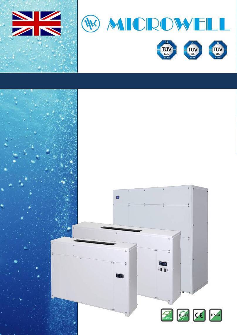
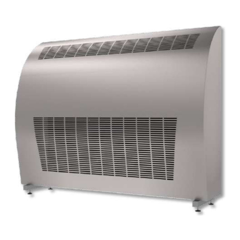
  9. MICROWELL DRY 800 METAL User manual

MICROWELL DRY 800 METAL User manual

ИНСТРУКЦИЯ
Microwell DRY800 Metal
MODEL: DRY 800 & 1200 METAL
SWIMMING POOL DEHUMIDIFIER
USER´S MANUAL
HUMIDISTAT
lDo not manipulate with the device with wet hands.
lDo not spray any flammable substances into the equipment; this might lead to fire.
lDo not clean the device with water.
lThe cover of the device is made of steel, coated by three anticorrosive layers, protected by two variants of surface
colours: silver metallic finish or white colour (METAL type).
lDo not clean the equipment with aggressive cleaning agents, this might lead to damage or deformations.
lNever throw or insert any objects into any tube or opening.
lUse this device only for the intended purpose, as described in the attached instructions for use. Do not use
components, which are not recommended.
lNever block the air opening of the product. Protect the air openings from clogging by particles, hair etc.
lWhen the device is not running correctly (smoke, smell, etc.), switch off the device by a circuit breaker in the
switchboard.
lRepairs and relocations must be performed only by a service technician.
lBefore cleaning the device, switch off the circuit breaker in the switchboard.
lDo not place any objects on the surface of the device.
lWhen you do not intend to use the device for a longer time, switch off the circuit breaker.
2
SWIMMING POOL DEHUMIDIFIER - USER´S MANUAL
1. SAFETY MEASURES
2. USAGE SPECIFICATION
The units are designed especially for use in indoor swimming pools, spas and saunas. They can also be very useful in laundries,
drying rooms and elsewhere.
Microwell DRY 800 METAL is designed for use in swimming pool halls with 60 to 90m² swimming pools.
Microwell DRY 1200 METAL is designed for use in swimming pool halls with 90 to 120m² swimming pools.
The condition of using the equipment is keeping a room temperature within a range between min. 22 °C and max. 35 °C.
Optimal situation occurs when the room temperature is about 2-3 C ° higher than a swimming pool water-temparature.
EXHAUST GRID
INTAKE GRID
UNIT COVER
Thank you for purchasing our product.
Please read this user manual carefully before starting to use the device.
Please keep the instructions of this practical quide in order to get a quick know-how.
We do not take any responsibility or provide warranty in case of damage, loss or damnification caused by
incorrect usage or usage for other purposes, not specified in this manual.
Contents: 1. Safety measures
2.
3. Instructions for use
4. Instructions for maintenance
5. Servicing the unit
6. Installation guide
7. Technical data
Usage specification
The inbuilt humidistat is located in the cover of the device. It reads the humidiy of the incoming air, and depending on the set value,
switches on the compressor. In indoor swimming pool halls, the optimal air humidity level should range between 55% and 65 %.
Decreasing the level of humidity under the above mentioned range is not desirable, considerating the physiological aspects as well
as the aspects of providing building protection. Moreover, it increases the consumption of electrical energy. The humidistat can be
controlled by the user.
3.
3.1.
INSTRUCTIONS FOR USE
Humidity regulation with an inbuilt digital humidistat located in the cover of the equipment
3
SWIMMING POOL DEHUMIDIFIER - USER´S MANUAL
Humidistat display (front view)
Luminous point
signals, that the
humidity is shown on
display.
Luminous point indicates that
the regulator gives signal to
dehumidify, i.e. requested
humidity is lower than actual.
Luminous point indicates
that the regulator gives
signal to heat the air. This is
applicable if LPHW and
Solenoid valve are installed.
Not illuminated point
indicates that the requested
air temperature is lower than
actual.
Luminous point signals,
that the temperature is
shown on display.
Failure reporting
Memory failure. Switch off and then switch on again the electrical connection.
If the failure reporting continues, please ask us to change the component.
Sensor failure. The electrical connection of the sensor is broken off.
Please control the cable.
Sensor failure. The sensor is short-circuited. Please control the cable.
Er1
0-E
S-E
4
SWIMMING POOL DEHUMIDIFIER - USER´S MANUAL
By keeping the “set” button pressed for longer than 5 secs, the setting gets finished and you return to a mode of current
humidity display.
In case of inactiveness for longer than 30 secs, this is done automatically.
3.2. Humidity regulation with a back-up mechanical humidistat located in the electronic box
In the electronic box there is a back-up mechanical humidistat, which is set on the value of 70 % RH. This humidistat has a back-up
function in case of digital humidistat failure. User should not perform any regulation of this humidistat.
5
Condensed water is drained from the device by the force of gravity. It is necessary to locate the device in a way that enables
sufficient condensed water gradient. The condensate must be delivered through a siphon into the sewer or into the outside
environmemt. It is strictly forbidden to deliver the condensate back into the swimming pool, as it may be bacterially contaminated.
There is a tube for condensed water delivery located at the bottom of the device, on the left side. This tube must be plugged into
a sewerage pipe with an internal diameter min. 18 mm.
6.4. Condensate drain
SWIMMING POOL DEHUMIDIFIER - USER´S MANUAL
The cover can be disassembled by releasing of two screws located at the side parts of the device. Release the screws, pull the
bottom part of the cover toward yourself and then, by lifting it shortly, rake down the cover from the rear plate. The unit installation
is performed in an adverse way.
6.3. Dismounting and mounting of the cover
The unit must be installed in compliance with the local installation and electrical installation regulations !
6.1. Unit location
The unit is to be installed on the floor or on the wall. To ensure the right operations of the dehumidifier and its maximum efficiency in
terms of humidity control, it is necessary ensure proper air circulation into and from the dehumidifier. This requires the actual unit
placement appropriately into the swimming pool hall respecting basic prerequisites of air circulation and air flow. It is strictly
forbidden to install the unit just below the ceiling. At least 200mm of a free space must be kept above the unit. Each swimming pool
hall is individual thus a special care needs to be taken to choose a proper dehumidifier placement. It is also strictly forbidden to block
the air inlet and outlet with any objects (canoe, buckets, ceiling beams, etc.). For maintenance purposes please keep free space of
200mm on both sides of the dehumidifier.
6. INSTALLATION GUIDE
The equipment has a self-supporting construction and is very easy to install.
There is an elevated adjustable stand included in the equipment accessories.
6.2. Equipment fixation
The compressor´s operation starting is for securing its protection, delayed by min. 3 minutes. Depending on the humidity of
environment, it may last even longer. The user must not manipulate with the setting element of a time relay.
3.3. Compressor regulation
It is necessary to make sure that the intake and exhaust outlets are not covered. It is forbidden to place towels or other clothes
on the exhaust outlets to dry them. Cleaning of the device´s cover is allowed only by using non-abradant cleaning agents. In case
there is a water dripping from the equipment, please check whether a condensate pipe is not obstructed.
At least once a year, it is necessary to have the unit checked and cleaned by a service specialist. This is necessary in order to secure a
long operational life of the device. Cleaning the interior parts of the device by a user is not recommended, as this may lead to a
damage on the unit. The device contains mobile elements as well as elements under electrical pressure, therefore the interior parts
can be cleaned only by a certified electrician with an appropriate knowlegde of refrigerating technology.
4. MAINTENANCE INSTRUCTIONS
5. SERVICING THE UNIT
600
280
50
90
50
95
50
60
POWER SUPPLY/FROM BACKSIDE/
2
- CYSY WIRE 3C x 2.5 mm
CONDENSATE DRAINAGE (FROM BACKSIDE)
PIPING WITH MINIMUM INTERNAL DIAMETER OF 18 mm
THREAD G ½ '’ MALE
LOCATION OF CONNECTION /FROM BACKSIDE/
6
SWIMMING POOL DEHUMIDIFIER - USER´S MANUAL
The unit´s connection into the mains and its protection must meet the requirements of relevant norms. The connection
requirements are the following: 220-240 V/50 Hz, 16A protection secured by a current protector with a nominal differential shut-off
current not exceeding 30mA. There is a terminal board for connecting the unit to the main, located on the left hand side of the
device. The master switch of the device must be located outside the swimming pool hall and it must be bipolaric and with L and N
conductors´ disconnecting. The dehumidifier must be inbuilt to a steady point for disconnecting the appliance from the mains with
a minimum 3 mm distance between the contacts for all the poles and in a switched off status.
The dehumidifier´s connection to the mains must be performed only by a qualified professional.
The dehumidifiers are simply adapted also to installation behind the wall into the adjacent room. In such case, only two grids are
visible in the swimming pool area. In the configuration for installation behind the wall, conduit adapters are screwed onto
the dehumidifier´s backside sheet. The adapters are delivered for passage through the wall of the length of 400 mm. In the place
of installation, they are shortened from the side of the swimming pool as necessary.
Flanges on the direct pieces are slipped on, so they can be cut into appropriate sizes directly in a place of assembly. Afterwards
the flanges are rivetted. The set also includes sealing band and screws for flanges´ connection.
6.5 Connecting the device to the mains
6.6 Mounting behind the wall - to order
Side cut View from the swimming pool
The dimensions of building slots are quoted.
6.6.1 Installation outside
When the dehumidifier is installed outside, it is equipped with special insulation to prevent condensation. The insulation thickness
is 4cm K-Flex ALCLAD ST 19 R.
Back side of the unit is equipped with special double insulation with aluminum layer on the top.
When installing the through the wall ducts, please apply insulation on revealed places to prevent condensation. Please note that
typical swimming pool has 30°C and 60% RH. Due point in these conditions is 21.4°C. Outside temperature is lower than this value
for most of the year. It is thus essential to insulate all places where condensation may occur. Manufacturer supplied 2 pieces of
extra insulation for this purpose.
When unit is placed outside the unit is equipped with Winter module and Condensate tray defrost. Winter module keeps the
compressor temperature at certain level to maintain oil viscosity. This helps overall performance of the unit and long term
reliability. Winter module activates when compressor is off (no dehumidification) and outside temperature is lower than 2°C.
Condensate tray defrost is a standard feature applied when unit is used in subzero temperatures. The unit is by standard equipped
with heated and insulated condensation hose. Please do not cut or shorten the heating element. It works automatically when there
is ice or condensate formed and outside temperature is lower than 2°C.
Should your unit be equipped with a wireless control DRY EASY 300, then the antenna is packed inside the machine. During the
installation please take it out through the air OUT ducting and keep it inside the ducting. This will improve the quality of signal
transmission.
SWIMMING POOL DEHUMIDIFIER - USER´S MANUAL
7
6.8. Air filter - to order
Your dehumidifier may be equipped with an air filter on demand. Air filter is to gather dust and other mechanical particles and
prevent them entering aluminum heat exchangers. Although air filter contributes to cleanness of your dehumidifier, it has no HEPA
(antibacterial) filter functionality.
Your dehumidifier's operation is very much dependent on continuous free air supply. It is then important to keep your filter clean.
Please review simple steps below how to clean your filter. In the case filter is not cleaned it creates a barrier for air supply. This has
negative effect to your dehumidifier's operation and may result in its malfunction, damage or a complete failure. Some pools require
cleaning once a year, some once a month some once a week. Time period in which your filter needs to be cleaned is very much
dependent on actual individual conditions in your pool hall. It is then required to clean the filter at least once a month. Manufacturer,
distributor or resellers are not responsible for malfunctions, damages or failures resulting from not cleaned filter.
When exchanging the filter power supply to the dehumidifier must be cut and the unit turned off.
1. Remove the dehumidifier cover.
Please watch out for controller
connectors such as cables or
antennas!
2. Unscrew 2 screws on the right
side and slightly release 3 screws
on the left side.
3. Lift the filter and move it down-
left-ward.
4. Remove the filter from the
dehumidifier.
5. Clean the filter using vacuum machine or rinse with fresh warm water. If needed you may apply non aggressive cleaning agent. Please let the filter dry in
shade. Do not expose the filter to sun.
6. Please install the filter back by undertaking above steps in reversed order.
The LPHW heater elements are supplied only to order. Connection of the hot water heater element onto the LPHW plumbing is
carried out similarly to the installation of radiators. On the feeder pipe, it is connected by a control valve and on the return pipe by a
closing screw joint. The LPHW is not supplied with a control valve and a screw joint; these are supplied by the supplier of the
heating.
6.7. LPHW heater element - to order
Attachment of the heater element to the distribution of the heating water
After installing the LPHW plumbing and leading the LPHW into the element under pressure, it is necessary to bleed the heater
element. The bleeding valve is located on the feeder pipe of the LPHW heater element. To secure that the LPHW heater element
works always at full heat output, blowing onto the unit by a fan must be provided even when no dehumidification is being
performed. Therefore, when using the LPHW heater element, the switch of fan operation must be switched into the position of
continuous operation.
600
280
50
90
50
95
50
60
POWER SUPPLY/FROM BACKSIDE/
2
- CYSY WIRE 3C x 2.5 mm
CONDENSATE DRAINAGE (FROM BACKSIDE)
PIPING WITH MINIMUM INTERNAL DIAMETER OF 18 mm
THREAD G ½ '’ MALE
LOCATION OF CONNECTION /FROM BACKSIDE/
SWIMMING POOL DEHUMIDIFIER - USER´S MANUAL
6.9. Electrical heating
On demand your swimming pool dehumidifier can be equipped with electrical heater. This is a stainless steel resistance tube in
aluminum fin exchanger. Capacity 2-4kW.
The electrical heater has separate power supply connection located in the dehumidifier power supply
connection black box located on the electro box.
The electrical heater is equipped with 2 security off switches.
The electrical heater is turned on and off according to requested air temperature settings on a dehumidifier’s controller /either built-
in digital or wireless DRY EASY 300/.
Please note that the main dehumidifier cover is made from metal. The upper part of this cover, during electrical heater operations,
may reach up to 65°C (at air temperature 35°C). It is thus forbidden to touch the metal cover at upper part of a dehumidifier during
its operations. It is also forbidden to allow children to play around or with the dehumidifier. Should
children be present in a room where the dehumidifier is installed, children are required to be
supervised by an adult all the time and are required not to touch the dehumidifier.
Connection:
2kW 2.5mm CYSY 16A Protection
4kW 4mm CYSY 25A Protection
Your machine can be equipped with IP44 power supply cord. It is required for user to use IP44
socket. Socket with lower protection than IP44 does not guarantee IP44 protection of the dehumifier.
When using IP44 power supply cord and socket:
- Do not place the plug and socket on wet places or places with leaking or dropping water
- Do not put any objects on a cable, do not use the cable for other purpose than a power supply of the machine.
- Place the cable off other appliances such as heaters, motors, rotors, etc.
- Do not use the dehumidifier if the cable shows signs of damage.
- Always follow electrical installation requirements /e.g. circuit breaker, residual circuit breaker/.
- Children and non-authorized persons are not allowed to manipulate with cable or plug.
pp
p
8
7. Technical data
SWIMMING POOL DEHUMIDIFIER - USER´S MANUAL
The cooling circuit is filled with R410A refrigerant that consists of 2 components (R32/R125). These components
are considered as fluorocarbon greenhouse gases.
The product contains fluorocarbon greenhouse gases listed in the Kyoto Protocol:
R410A with the global warning potential (GWP) 1720
(R-32/125 50/50)
CH F + CF CHF
22 3 2
1200 g (DRY 800)
1600 g (DRY 1200)
DATA UNIT
DRY 800 DRY 1200
For swimming pools with max. water surface m2
90 120
Exctraction rate at 30°C and 60 % RH l/24hrs
90 120
Exctraction rate at 30°C and 70 % RH l/24hrs
115 150
Exctraction rate at 30°C and 80 % RH l/24hrs
136 181
Operational temperature - standard °C
22-35 22-35
Operational temperature - antifreeze stat °C
15-35 15-35
Operational temperature - Thermostatic expansive valve (TEV) °C
--
Operational temperature - antifreeze stat + TEV °C
--
Operational temperature - hot gas defrost °C
--
Operational humidity range % RH
20-100 20-100
Air flow m3/h
1000 1000
Noise level (in 1m distance) dB (A)
44 44
Heat output W
5100 5250
Energy consumption W
1700 1750
Voltage V/Hz/f
230/50/1 230/50/1
Operating / Starting current A
7.5 / 50 7.6 / 50
Protection A
16 16
Conductor mm2
CYSY 3C x 2,5 CYSY 3C x 2,5
Condensed water pipe mm
d 18 d 18
Dimensions netto (width x height x depth) mm 1250 x 950 x 310 1250 x 950 x 310
Dimensions brutto (width x height x depth) mm 1300 x 1020 x 370 1300 x 1020 x 370
Weight netto / brutto kg
100 / 133 kg 101 / 134kg
Amount of refrigerant - R 410 A kg
1,25 1,6
Max. pressures in the system HP/LP bar 35/12 35/12
Relative humidity
Dehumidification output
Air temperature
OUTPUT DIAGRAM OF DEHUMIDIFICATION (DRY 800 METAL)
OUTPUT DIAGRAM OF DEHUMIDIFICATION (DRY 1200 METAL)
0
20
40
60
80
100
120
140
160
15 20 25 30 35 °C
80%
70%
60%
50%
40%
l/24 h.
Dehumidification output
Air temperature
Relative humidity
0
20
40
60
80
100
120
140
160
180
200
220
15 20 25 30 35
(l/24h)
(°C)
80%
70%
60%
50%
40%
9
SWIMMING POOL DEHUMIDIFIER - USER´S MANUAL
WIRING DIAGRAM OF MODEL MICROWELL DRY 800 METAL
DRY 800.1
Note: Producer reserves right to make changes on wiring.
10
Note: Producer reserves right to make changes on wiring.Note: Producer reserves right to make changes on wiring.
SWIMMING POOL DEHUMIDIFIER - USER´S MANUAL
11
SWIMMING POOL DEHUMIDIFIER - USER´S MANUAL
Note: Producer reserves right to make changes on wiring.
DRY 800.2
12
Note: Producer reserves right to make changes on wiring.Note: Producer reserves right to make changes on wiring.
SWIMMING POOL DEHUMIDIFIER - USER´S MANUAL
13
Note: Producer reserves right to make changes on wiring.Note: Producer reserves right to make changes on wiring.
SWIMMING POOL DEHUMIDIFIER - USER´S MANUAL
WIRING DIAGRAM OF MODEL MICROWELL DRY 1200 METAL
DRY 1200.1
14
Note: Producer reserves right to make changes on wiring.Note: Producer reserves right to make changes on wiring.
SWIMMING POOL DEHUMIDIFIER - USER´S MANUAL
15
Note: Producer reserves right to make changes on wiring.Note: Producer reserves right to make changes on wiring.
SWIMMING POOL DEHUMIDIFIER - USER´S MANUAL
DRY 1200.2
16

Other manuals for DRY 800 METAL

1

This manual suits for next models

1

Other MICROWELL Dehumidifier manuals

MICROWELL DRY 1200 METAL User manual

MICROWELL

MICROWELL DRY 1200 METAL User manual

MICROWELL DRY 300 PLASTIK User manual

MICROWELL

MICROWELL DRY 300 PLASTIK User manual

MICROWELL DRY 300 PLASTIK User manual

MICROWELL

MICROWELL DRY 300 PLASTIK User manual

MICROWELL DRY 1200 METAL User manual

MICROWELL

MICROWELL DRY 1200 METAL User manual

MICROWELL DRY 300 User manual

MICROWELL

MICROWELL DRY 300 User manual

MICROWELL DRY 300 PLASTIK User manual

MICROWELL

MICROWELL DRY 300 PLASTIK User manual

MICROWELL DRY 300 DUCT Operating manual

MICROWELL

MICROWELL DRY 300 DUCT Operating manual

MICROWELL T90 User manual

MICROWELL

MICROWELL T90 User manual

MICROWELL DRY 300 PLASTIK User manual

MICROWELL

MICROWELL DRY 300 PLASTIK User manual

MICROWELL DRY 800 METAL User manual

MICROWELL

MICROWELL DRY 800 METAL User manual

MICROWELL DRY 300 SILVER Guide

MICROWELL

MICROWELL DRY 300 SILVER Guide

MICROWELL DRY 500 User manual

MICROWELL

MICROWELL DRY 500 User manual

Popular Dehumidifier manuals by other brands

LG LD106F Series owner's manual

LG

LG LD106F Series owner's manual

Aerus Pure & Dry user manual

Aerus

Aerus Pure & Dry user manual

Sullair SD Series user manual

Sullair

Sullair SD Series user manual

DeLonghi DDSX 220WF-WH manual

DeLonghi

DeLonghi DDSX 220WF-WH manual

Trane EDHUM070H Installation & operation instructions

Trane

Trane EDHUM070H Installation & operation instructions

Anden 5859 installation instructions

Anden

Anden 5859 installation instructions

ENVIROBOSS EB130 owner's manual

ENVIROBOSS

ENVIROBOSS EB130 owner's manual

Goldair GD260 operating instructions

Goldair

Goldair GD260 operating instructions

Parker Airtek MSC Series user guide

Parker

Parker Airtek MSC Series user guide

Keystone R-KSTAD50B user manual

Keystone

Keystone R-KSTAD50B user manual

El-Björn A 75FT manual

El-Björn

El-Björn A 75FT manual

Anslut 014956 operating instructions

Anslut

Anslut 014956 operating instructions

Bionaire BD10 instruction manual

Bionaire

Bionaire BD10 instruction manual

Woods DS40FS user manual

Woods

Woods DS40FS user manual

GOTEL WB-EDH19-005 user manual

GOTEL

GOTEL WB-EDH19-005 user manual

Ebac CD425 owner's manual

Ebac

Ebac CD425 owner's manual

Costway ES10261US manual

Costway

Costway ES10261US manual

Phoenix DryMAX 4036000 Installation, operation & service instructions

Phoenix

Phoenix DryMAX 4036000 Installation, operation & service instructions

manuals.online logo
manuals.online logoBrands
  • About & Mission
  • Contact us
  • Privacy Policy
  • Terms and Conditions

Copyright 2025 Manuals.Online. All Rights Reserved.