manuals.online logo
Brands
  1. Home
  2. •
  3. Brands
  4. •
  5. Jøtul
  6. •
  7. Fireplace Accessories
  8. •
  9. Jøtul GF 100 BF2 Owner's manual

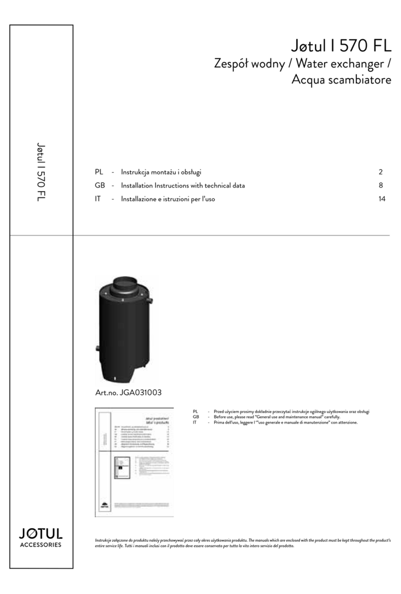
Jøtul GF 100 BF2 Owner's manual

Kullsett/Coal Set
for Jøtul GF 100 BF2
Jøtul GF 3BF2
Jøtul GI 160 BF
Monterings- og bruksanvisning - Norsk 2
Installation and Operating Instructions- English 3
Figures/Pictures 4
Jøtul GF 100BF2/GF 3 BF2
Jøtul GI 160 BF
Monterings- og bruksanvisningen må oppbevares under hele produktets levetid.
These instructions must be kept for future references.
2
Montering av kullsett
Pakk ut esken med kullsett.
OBS! Vær oppmerksom på at kullene,som er av et keramisk
materiale, kan irritere ømfintlig hud. Bruk hansker når
kullene skal berøres.
Før kullsettet plasseres, må braketten under
brennkammeret byttes ut med den som følger kullsettet.
Montering av luftregulator
1. Fjern platen for sekundærluft (fig. 3A).
2. Vingemutteren (fig. 1A), skiven (fig. 1B) og styrebraketten
(fig. 2B) skrus av.
3. Erstatt braketten under brennkammeret med den som
som følger kullsettet (fig. 1C). Fest braketten med
vingemutter/skive løst under produktet (utstanset del
(fig. 2C) må vende vekk fra hoveddysen). Se fig. 1 og 3:
Venstre hull (fig. 1,2) for LPG – full åpning 26 mm.
Høyre hull (fig. 1,1) for NG 20 - minimum åpning 2,5 mm.
(Justering må gjøres etter tilkobling av gassen.)
4. Legg luftregulatoren i styrebraketten.
5. Monter brenneren, og legg på plass underlagsbraketten
for ved-/kullsett. Sjekk at brenneren ligger flatt, og at
luftspalten i forkant er lik.
6. Hvis trekkbegrensning er nødvendig, monteres denne
nå i følge avtrekksdiagram. (Se hovedmanual.)
Justering av luftregulator
7. For å oppnå et best mulig flammebilde (gjelder kun NG
20) må man ofte justere blandingen av gass/luft.
Begynn med å skyve styrebrakettens vingemutter til
midtre posisjon (fig. 1).
Ved å skyve vingemutteren mot venstre, vil
lufttilførselen innskrenkes.Ved å skyve den mot høyre,
vil lufttilførselen økes.Ved noe utprøving vil den beste
posisjonen for hver enkelt installasjon oppnås.
8. Skru vingemutteren godt til igjen.
Plassering av kullsett
Begge de store matrixene har hull på undersiden. Når disse
skal plasseres, skal hullene passe over tappene.
Fig. 5 Legg den største matrixen opp på bakre kant.
Kontroller at den ligger mot ytterkant.
Fig. 6 Legg noen små kull (glør) på braketten slik som
figuren viser. Ikke plasser for mange på brenneren
da dette kan forstyrre flammebildet.
Fig. 7 Legg på midtre matrix og kontroller at den berører
den venstre del av den bakre matrix.
Fig. 8 Plasser de to frontkullene. Disse er merket L=venstre
og R= høyre. Kontroller at de ikke blokkerer
flammehullene og at de ligger stødig.
NORSK
Fig. 9 Plasser 6 store runde kull mellom frontkullene og
midtre matrix, og legg 5 mellom midtre og bakre
matrix. Se til at mellomrommene blir noenlunde like.
Fig. 10 Plasser 4 små kullstykker på bakre matrix og 1 på
hver side. Hvis mulig, se til at de ikke ligger i veien for
flammene.
Etter å ha brukt ildstedet en stund må kanskje kullene
justeres litt, slik at flammene ser like ut og er like høye.
3
Mounting of the coal set
Unpack the box which include the coal set.
NB! Use gloves to handle the coals, as they can cause skin
irritation.
Before placing the coal set, the bracket under the burn
chamber must be exchanged with the one included in the
coal set.
Mounting the air regulator
1. Remove the secondary draught plate (fig. 3A).
2. Remove the wing nut (fig. 1A), the washer (fig. 1B), and
the control bracket (fig. 2B).
3. Exchange the control bracket under the burn chamber
with the one following the coal set (fig. 1C). Fasten the
bracket loosely with the wing nut and washer under
the product. (The punched part (fig. 2C) must be turned
away from the main orifice). See fig. 1 and 3:
Left hole (fig. 1,2) for LPG - fully open 26 mm.
Right hole (fig. 1,1) for NG 20 (for Norway)- minimum
opening 2,5 mm. (Any adjustments must be made after
the gas has been re-connected).
4. Replace the air regulator in the control bracket.
5. Mount the burner and place the underlay bracket for
the coal set/log set in position. Check that the burner is
lying flat and that the air separators on the front edge
are equal.
6. If an exhaust restrictor is necessary, mount this now in
accordance with the exhaust diagram. (See main
manual.)
Adjusting the air regulator
7. In order to achieve the best possible flame (only NG 20)
you will need to adjust the gas/air mixture often.
Begin by sliding the control bracket’s wing nut to the
middle position (fig. 1). By sliding the wing nut to the left,
the air supply is reduced. By sliding the wing nut to the
right, the air supply is increased.
You can find the best position for each installation by
trial and error.
8. Screw the wing nuts tight.
Placing of the coal set
Both the large matrixes have holes underneath to be
located on the pins.
Fig. 5 Put the large matrix on the bracket locating on the
pins and make sure it is in front of the back flange
of the bracket.
Fig. 6 Put a few embers along the front and back burner
ports right around the burner as the figure shows.
Do not place too many on the burner as this may
lead to flame picture difficulties
ENGLISH
Fig . 7 Put the centre matrix in place on the pins of the
burner and make sure it touches the left part of the
back matrix.
Fig. 8 Put the left and right front coal pieces (marked L&R
on back) on the bracket making sure that they do
not block the flame holes. Make sure that they stand
firmly on their bases.
Fig. 9 Place the 6 larger coals as shown onto the front
coals and the centre matrix, and 5 pieces between
the centre and back matrix. Make the gaps quite
even between the pieces.
Fig. 10 Place the 4 small coal pieces between the larger
coals on the back matrix, and also one piece on each
side. Make sure that they don’t get into the flames
if possible.
After burning the stove for a while, re-adjust any of the
coals so that the flames are even and not larger at any
point.

4
Fig 2
Fig 3
Fig 1
5
A
Fig. 4
Fig. 5
Fig. 6
Fig. 7
Fig. 8
Fig. 9
Fig.10
6
7
Jøtul arbeider kontinuerlig for om mulig å forbedre sine produkter,og vi forbeholder oss rett til
å endre spesifikasjoner, farger og utstyr uten nærmere kunngjøring.
Jøtul pursue a policy of constant product development. Products supplied may therefore differ
in specifiaction, colour and type of accessories from those illustrated and described in the
brochure.
Kvalitet
Jøtul AS arbeider etter et kvalitetssikringssystem basert på NS-EN ISO 9001 for utvikling,
produksjon og salg av ildsteder. Vår kvalitetspolitikk skal gi kundene den trygghet og
kvalitetsopplevelse som Jøtul har stått for siden bedriftens historie startet i 1853.
Quality
Jøtul AS has a quality system that conforms to NS-EN ISO 9001 for product development,
manufacturing, and distribution of stoves and fireplaces. This policy gives our customers quality
and safety piece of mind as a result of Jøtul’s vast experience dating back to when the company
first started in 1853.
Cat.no. 221228
Draw.no.4-4311-P00
Jøtul AS, Sept. 05
Jøtul AS,
P.o. box 1411
N-1602 Fredrikstad,
Norway
Dette produktet er kontrollert av:
This product has been controlled by:
_________________________ ___________________
Date: Sign:

This manual suits for next models

2

Other Jøtul Fireplace Accessories manuals

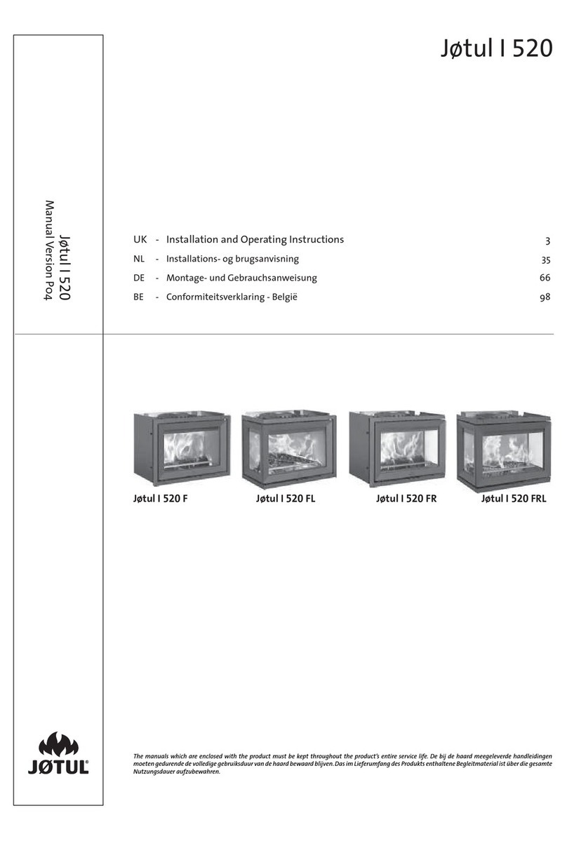
Jøtul 341280 User manual

Jøtul

Jøtul 341280 User manual

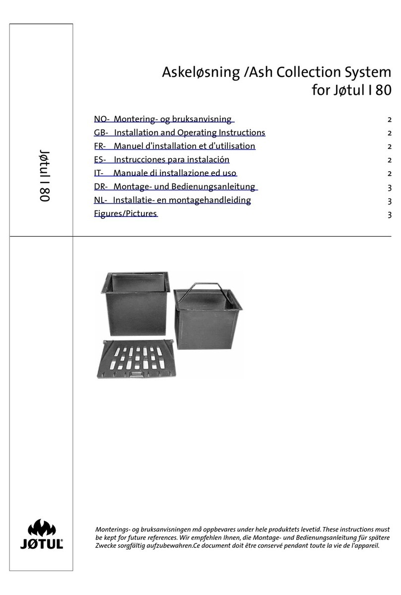
Jøtul I 80 User manual

Jøtul

Jøtul I 80 User manual

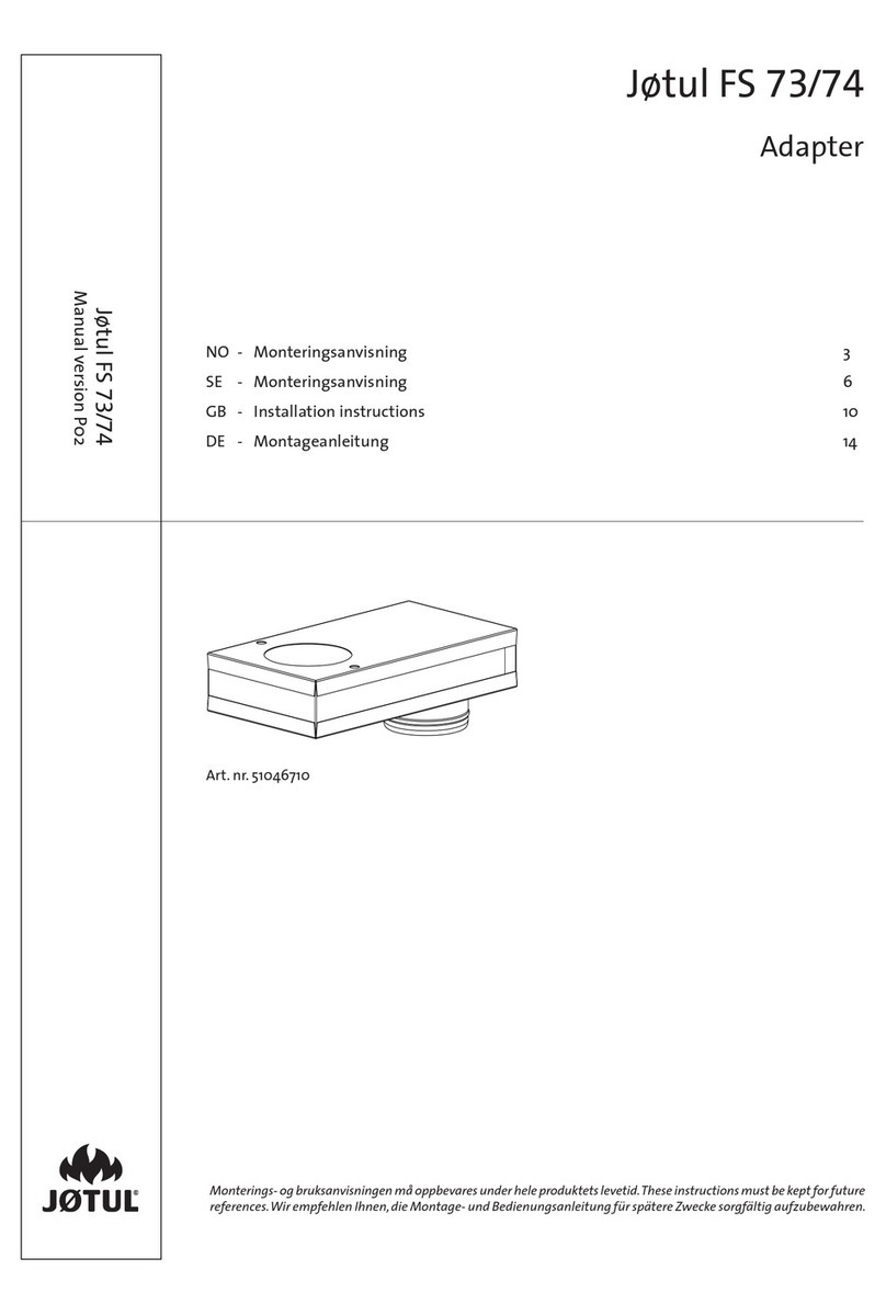
Jøtul FS 73 User manual

Jøtul

Jøtul FS 73 User manual

Jøtul 341273 BP User manual

Jøtul

Jøtul 341273 BP User manual

Jøtul I 570 FL Instruction manual

Jøtul

Jøtul I 570 FL Instruction manual

Jøtul 520 Series User manual

Jøtul

Jøtul 520 Series User manual

Jøtul F 602 N User manual

Jøtul

Jøtul F 602 N User manual

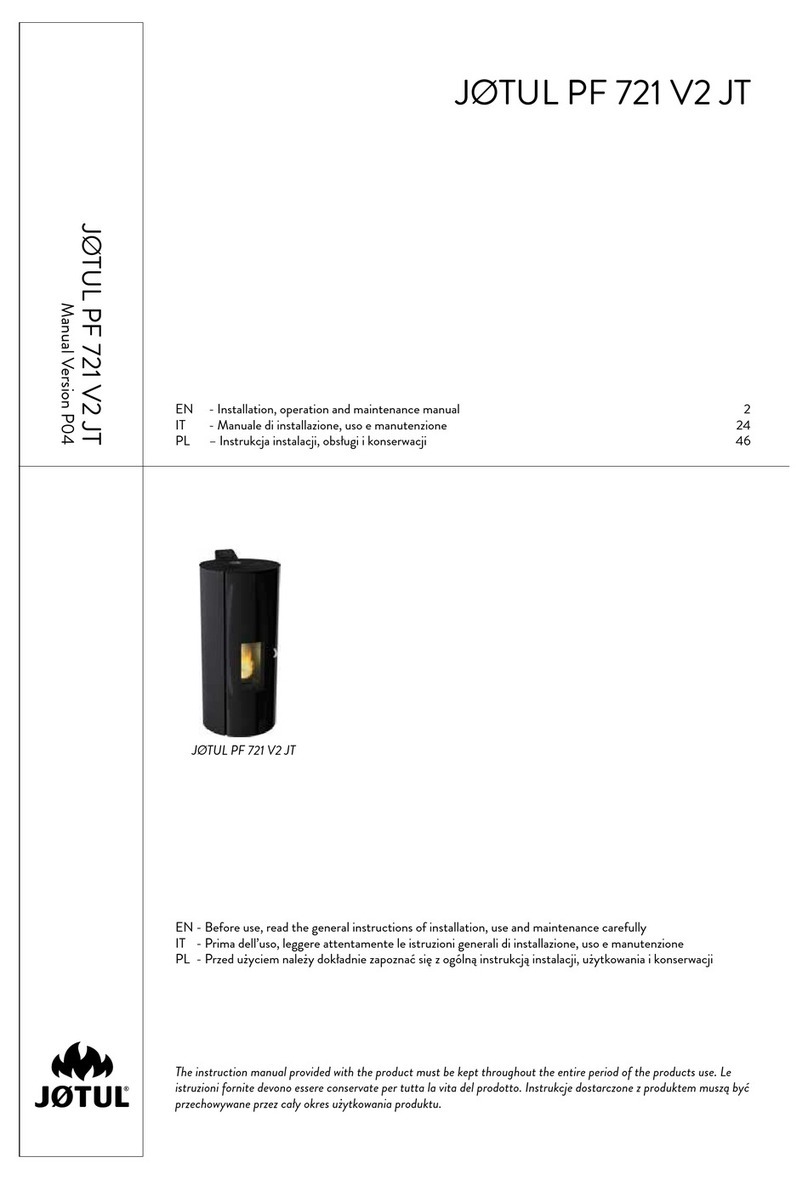
Jøtul PF 721 V2 JT User manual

Jøtul

Jøtul PF 721 V2 JT User manual

Popular Fireplace Accessories manuals by other brands

IHP PCBE-36 Operation manual

IHP

IHP PCBE-36 Operation manual

Bluegrass Living BC18NR OWNER'S OPERATION AND INSTALLATION MANUAL

Bluegrass Living

Bluegrass Living BC18NR OWNER'S OPERATION AND INSTALLATION MANUAL

Style selections LOG RACK WITH STORAGE SHELF 15261L Assembly instructions

Style selections

Style selections LOG RACK WITH STORAGE SHELF 15261L Assembly instructions

Uniflame Fireplace Furnishing brochure

Uniflame

Uniflame Fireplace Furnishing brochure

Valor GV60NTK Installation & operation instructions

Valor

Valor GV60NTK Installation & operation instructions

IHP DWLS-RNCL35 installation instructions

IHP

IHP DWLS-RNCL35 installation instructions

Hearth and Home Technologies GFK-160VF installation instructions

Hearth and Home Technologies

Hearth and Home Technologies GFK-160VF installation instructions

Lennox Hearth Products Crestline Decorative Hood Kits LDGHK36 installation instructions

Lennox Hearth Products

Lennox Hearth Products Crestline Decorative Hood Kits LDGHK36 installation instructions

Ashley ASHFSMK-W Assembly and installation

Ashley

Ashley ASHFSMK-W Assembly and installation

Town & Country Fireplaces TC30 Black Diamond instructions

Town & Country Fireplaces

Town & Country Fireplaces TC30 Black Diamond instructions

Empire Comfort Systems 41052 installation instructions

Empire Comfort Systems

Empire Comfort Systems 41052 installation instructions

Desa Mantel and Base W26RO Assembly and installation instructions

Desa

Desa Mantel and Base W26RO Assembly and installation instructions

Valor 1170RGL Refl ective Glass Liner Set installation instructions

Valor

Valor 1170RGL Refl ective Glass Liner Set installation instructions

WERKAPRO 10820 manual

WERKAPRO

WERKAPRO 10820 manual

Lennox BELLA-BPK-T installation instructions

Lennox

Lennox BELLA-BPK-T installation instructions

Blue Sky Outdoor Living TT22SQ owner's manual

Blue Sky Outdoor Living

Blue Sky Outdoor Living TT22SQ owner's manual

Napoleon ROGUE SE625-1 Quick assembly guide

Napoleon

Napoleon ROGUE SE625-1 Quick assembly guide

Dimplex SEP-M-4210-FB manual

Dimplex

Dimplex SEP-M-4210-FB manual

manuals.online logo
manuals.online logoBrands
  • About & Mission
  • Contact us
  • Privacy Policy
  • Terms and Conditions

Copyright 2025 Manuals.Online. All Rights Reserved.