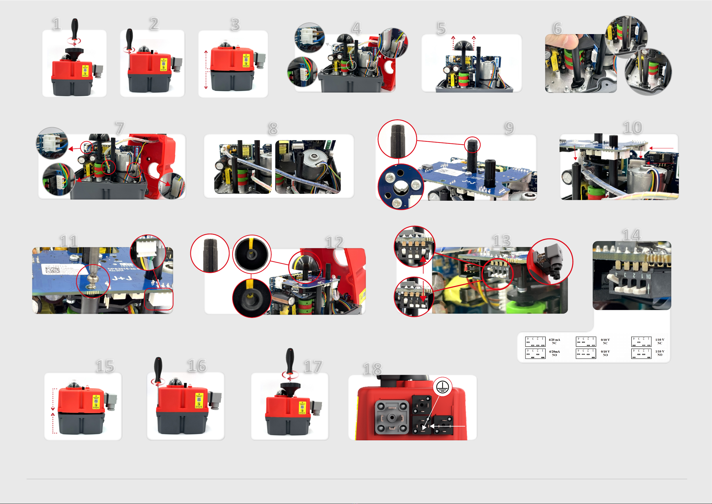
J4C DPS User manual

INDEX/ÍNDICE
(EN)
MOUNTING INSTRUCTIONS DPS KIT
J4C 20 TO 85
(ES)
INSTRUCCIONES MONTAJE KIT DPS
J4C 20 A 85
(EN)
MOUNTING INSTRUCTIONS DPS KIT
J4C 140 TO 300
(ES)
INSTRUCCIONES MONTAJE KIT DPS
J4C 140 A 300
.....................................................................................................................................................................
2
.....................................................................................................................................................................
5
............................................................................................................................................................
8
............................................................................................................................................................
11

DPS KIT J4C 20 TO 85
(EN)
ASSEMBLY INSTRUCTIONS
The DPS is a device for the J4C electric actuator
that turns the actuator into a servo controlled
valve posioner.
The DPS is a modulus with a microprocessor (CPU)
which digitally manages the analogical input and
output and compare them with the posion of the
actuator to establish a uniform relaon.
The analogical inputs are sent to the CPU where
they are processed for his connuous comparison
with the posion of the actuator, this allows to
obtain a very high sensivity next to a very high
repevity of the posion (see characteriscs).
The DPS in communicaon with the electronic
system of the actuator provides an integral mana-
gement of the moon of the actuator.
OUTSIDE BOX INSIDE BOX
02
INDEX

03
INDEX
ENGLISH -
ASSEMBLY INSTRUCTIONSDPS KIT 20/85
ENGLISH -ENGLISH -
ASSEMBLY INSTRUCTIONS
KIT COMPONENTS
Element A - 1 Cover
Element B- 1 Plasc column
Element C- 1 DPS posioner PCB
Element D- 2 Sheet metal Fixing screws
Element E- 1 Plasc Fixing screws
PREPARING THE COVER:
The cover of the kit is for a J4C - 20, 35 and 55 models. In case you want to mount a kit on a J4C85,
follow the instrucons:
A
C
B
Remove the
sleeve 1and
leave the
Oring inside.
sleeve
O-ring
1
D
E
Introduce the
sleeve in hole
A and press it
unl is fully
inside (Fig.A)
introduce the
cap in hole B
and press it
unl it is fully
inside (Fig.B)
sleeve
cap
PLEASE READ CAREFULLY BEFORE MOUNTING.
VERY IMPORTANT!!!! PLEASE FOLLOW THE INSTRUCTIONS STEP BY STEP. BEFORE CONNECTING “A” PLUG TO THE
ACTUATOR,
CHECK THAT THE VOLTAGE IS THE SAME AS THE ONE SPECIFIED ON THE LABEL (CARTER).
TO CONVERT A STANDARD (ON-OFF) J4C ELECTRIC ACTUATOR INTO A MODULATING FUNCTION WITH POSITIONER,
PROCEED AS FOLLOWS:
Remove the
cap and leave
the o-ring
inside the hole
cap
O-ring
AB
* Fill in the document inside the kit, and send it to the fax number (93 871 32 72) or e-mail: in[email protected]om, shown in the document.

04
INDEX
23
1
Remove the screw, which is fixing
the hand wheel.
Remove the 6 screws, which are fixing
the body to the cover of the actuator
Carefully li the cover.
5
Carefully remove the posion indicator.
4
Remove the cables (from the cover) connected to the
actuator PCB (Fig. A, B and C).
A
B
C
10
JP3
JP2
9
Mount the DPS posioner PCB (Element C), matching the cle of
the sha with the key inside the DPS gear.
Press the DPS posioner PCB (Element C) along the sha unl the
PCB connector (JP3) is plugged in the actuator PCB connector (JP2).
11
Fix the DPS posioner PCB (Element C) to the plasc column (Element B) with the
plasc fixing screw (Element E) (Fig. A).
Connect the remaining cable (Element A) to the connector base on the DPS PCB
(Element C) (Fig. B).
A
B
Outer Set-Up: Only if necessary.
- B plug - Connect a cable between PIN 1 and PIN Earth.
- A plug - Connect it to the power supply.
- B plug, disconnect the cable between PIN 1 and PIN Earth.
The actuator will make a complete maneuver.
Connect B connector to the actuator. The actuator is ready to work.
Mount the 3 outer connectors together with its rubber joints and fix
them to the cover, by using the screws.
18
PIN 1
A
BC
Carefully mount the cover, minding the cables
not to be pressed.
15
Mount the hand wheel on the sha and fix
it by using the screw.
17
Fix the cover to the body by using the 6
screws.
16
7
Take the DPS cover (Element A) and connect its cables, following (Fig. A, B, C).
A
B
Place the menoned cables as per (Fig. A and B)
8
6
Fix the plasc column (Element B) on the base plate, by using
2 sheet metal fixing screws (Element D) (Fig. A, B and C).
A
B
C
C
A B
14
12
Carefully insert the posion indicator, matching its inner key with the cle of the sha.
Use the configuraon you need by
moving the DIPs, according to the
instrumentaon signal:
In order to set the actuator up, use the DIPs shown in the picture. Put DIP 1 in ON posion (Fig. A),
connect the grey connector to the power supply (Fig. C). Put DIP 1 back to the prior posion (Fig. B).
Wait unl the actuator make a complete maneuver.
13
B
A
C
B

DPS KIT J4C 20 A85
(ES)
INSTRUCCIONES DE MONTAJE
El DPS es un accesorio para los actuadores
eléctricos J4C que los convierte en posicionador
de válvulas servo controladas.
El DPS es un módulo que incorpora un micro-
procesador (CPU) el cual controla digitalmente la
entrada y la salida de señal analógica y compara
ambas con la posición del actuador a fin de
establecer una relación uniforme.
Las entradas analógicas son enviadas a la CPU
donde son procesadas en connua comparación
con la posición del actuador lo cual permite obte-
ner un muy alto grado de sensibilidad y una muy
alta repevidad de posición (ver caracteríscas).
EXTERIOR CAJA INTERIOR CAJA
05
INDEX

ASSEMBLY INSTRUCTIONS
COMPONENTES DEL KIT
Pieza A -
1 Tapa
Pieza B-
1 Columna de plásco
Pieza C-
1 Electrónica DPS
Pieza D-
2 Tornillos rosca chapa
Pieza E-
1 Tornillo rosca plásco
PREPARACIÓN DE LA TAPA:
La tapa del kit, viene montada para poder tapar J4C-20, 35 y 55. En caso de necesitar una tapa para un J4C85,
seguir las siguientes instrucciones:
A
C
B D
E
PARA EVITAR AVERIAS SIGA ESTAS INSTRUCCIONES CUIDADOSAMENTE
MUY IMPORTANTE!!!! ANTES DE CONECTAR EL ACTUADOR A LA CORRIENTE, REVISAR QUE EL VOLTAJE COINCIDA
CON EL DE LA ETIQUETA PEGADA AL ACTUADOR.
PARA CONVERTIR UN ACTUADOR ELECTRICO STANDARD J4C (ON-OFF) EN UN ACTUADOR CON POSICIONADOR,
PROCEDER DE LA SIGUIENTE MANERA:
Picar, rerar el
tapón y dejar el
anillo tórico
montado.
Rerar el
casquillo tapa 1
y dejar el
anillo tórico
montado
En el agujero A,
introducir el
casquillo tapa y
presionar hasta
su completa
introducción
(Fig.A)
casquillo
tapa
Tapón
Tapón
Anillo
tórico Anillo
tórico
casquillo
tapa
En el agujero B,
introducir el tapón
tapa y presionar
hasta su completa
introducción (Fig.B)
1AB
06
INDEX
ESPAÑOL
INSTRUCCIONES DE MONTAJE KIT DPS 20/85
-
* Rellenar el documento adjunto al KIT y enviarlo al número de fax (93 871 32 72) o por e-mail: inf[email protected]

23
1
Desatornillar el tornillo que fija el
volante y rerarlo.
Desatornillar el tornillo que fija el
volante y rerarlo.
Rerar cuidadosamente la tapa.
5
Rerar cuidadosamente el indicador visual de posición.
4
Desconectar el cableado de la tapa que está conectado
a la electrónica. (Fig. A, B y C).
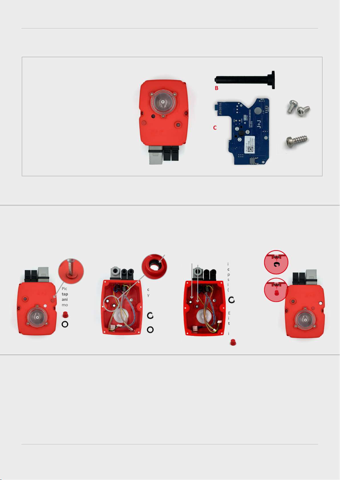
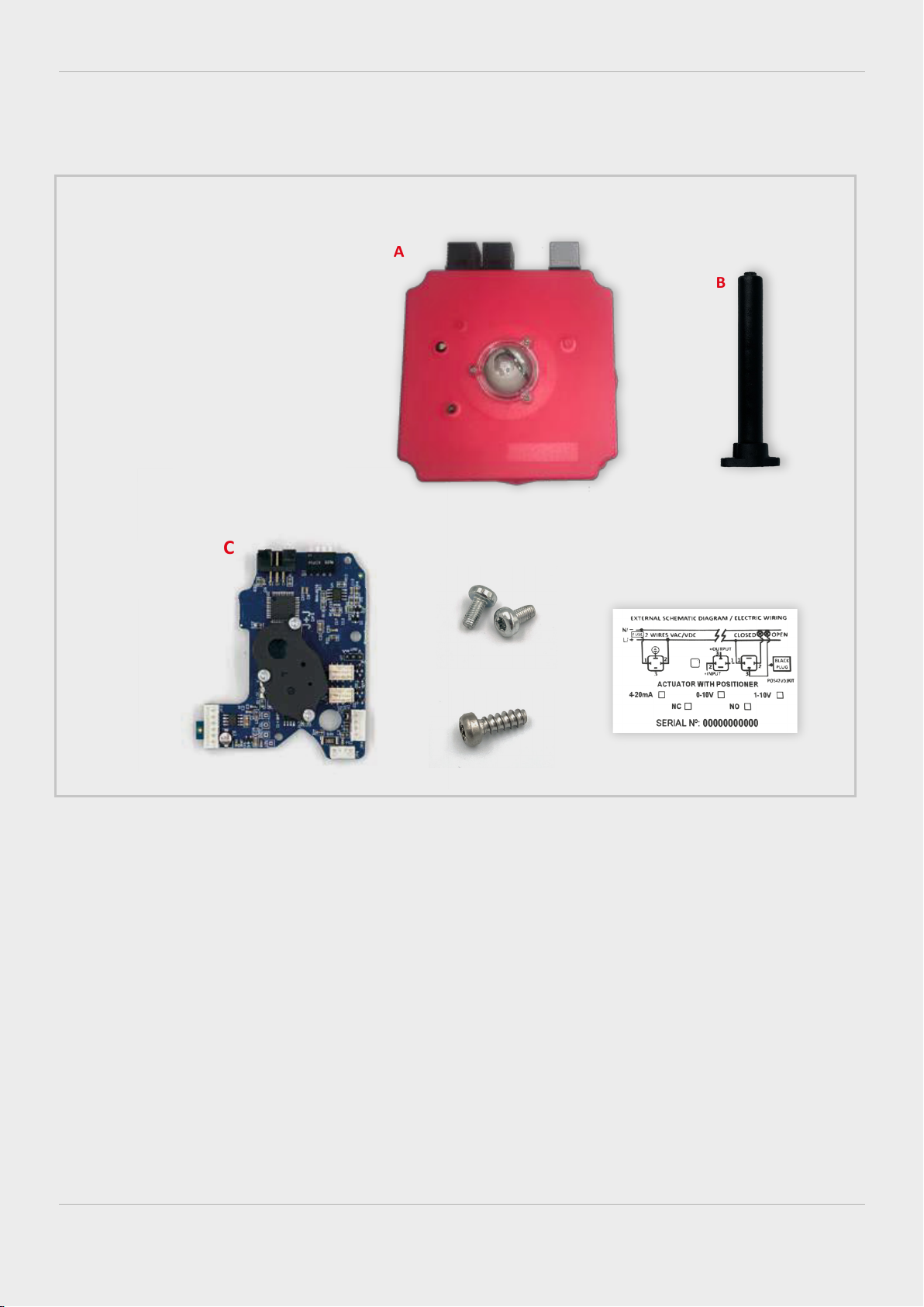
A
B
C
10
JP3
JP2
9
Montar la electrónica DPS (Pieza C), haciendo coincidir la
hendidura del eje con la chaveta del engranaje central.
Introducirla hasta que el conector de la electrónica DPS (JP3) esté
conectado con el conector (JP2) de la electrónica del actuador.
11
Fijar la electrónica DPS (Pieza C) a la columna de plásco (Pieza B) con el tornillo
rosca plásco (Pieza E) (Fig. A).
Insertar el cable sobrante de la tapa (Pieza A) en la base conector de la electrónica
DPS (Pieza C) (Fig. B).
A
B
Autoajuste externo: solo realizar en caso necesario
- En la base conector B: Hacer un cruce
entre el PIN1 y el PIN TIERRA. (Fig.19)
- En la base conector A: Conectar corriente.
- En la base conector B: Deshacer el cruce
entre el PIN1 y el PIN TIERRA.
El actuador realizara una maniobra completa. Conectar y fijar el
conector exterior B al actuador. El actuador ya está listo para trabajar.
Montar y fijar los conectores a la tapa (Fig.18). Comprobar que entre la
base y el conector se ha colocado una junta previamente.
18
PIN 1
A
BC
Montar la tapa, con cuidado de no aprisionar
los cables.
15
Montar y fijar el volante en el eje, haciendo
coincidir el perfil del volante con el del eje.
17
Fijar los 8 tornillos de unión entre la tapa
y el cuerpo.
16
7
Coger la tapa del kit DPS (Pieza A) y conectar el cableado según (Fig. A, B y C).
A
B
Situar el cableado de la tapa, según (Fig. A y B).
8
6
Fijar la columna de plásco (Pieza B) a la chapa del actuador,
mediante 2 tornillos rosca chapa (Pieza D). (Fig. A, B y C).
A
B
C
C
A B
14
12
Insertar cuidadosamente el indicador visual de posición, haciendo coincidir la chaveta
interior con la hendidura del eje.
Configurar los DIPs, según la señal de
instrumentación
Subir el DIP 1 a posición ON (Fig. A), conectar corriente al conector gris de la tapa del actuador (Fig. C).
Colocar el DIP 1 en la posición anterior (Fig.B) y esperar a que el actuador realice una maniobra completa.
Desconectar la corriente del conector gris de la tapa del actuador.
13
B
A
C
B
07
INDEX

DPS KIT J4C 140 TO 300
(EN)
ASSEMBLY INSTRUCTIONS
The DPS is a device for the J4C electric actuator
that turns the actuator into a servo controlled
valve posioner.
The DPS is a modulus with a microprocessor (CPU)
which digitally manages the analogical input and
output and compare them with the posion of the
actuator to establish a uniform relaon.
The analogical inputs are sent to the CPU where
they are processed for his connuous comparison
with the posion of the actuator, this allows to
obtain a very high sensivity next to a very high
repevity of the posion (see characteriscs).
The DPS in communicaon with the electronic
system of the actuator provides an integral mana-
gement of the moon of the actuator.
OUTSIDE BOX INSIDE BOX
08
INDEX

PLEASE READ CAREFULLY BEFORE MOUNTING.
VERY IMPORTANT!!!! PLEASE FOLLOW THE INSTRUCTIONS STEP BY STEP. BEFORE CONNECTING “A” PLUG TO
THE ACTUATOR, CHECK THAT THE VOLTAGE IS THE SAME AS THE ONE SPECIFIED ON THE LABEL (CARTER).
TO CONVERT A STANDARD (ON-OFF) J4C ELECTRIC ACTUATOR INTO A MODULATING FUNCTION WITH
POSITIONER, PROCEED AS FOLLOWS:
KIT COMPONENTS
Element A
- 1 Cover
Element
B - 1 Plasc column
Element
C - 1 DPS posioner PCB
Element
D - 2 Sheet metal Fixing
screws
Element
E - 1 Plasc Fixing screws
Element
F - 1 Schemac
diagram label
A
B
CD
E
F
* Remember to sck the (F) label on the actuator.
09
INDEX
ENGLISH -
ASSEMBLY INSTRUCTIONSDPS KIT 140/300
ENGLISH -ENGLISH -
ASSEMBLY INSTRUCTIONS
* Fill in the document inside the kit, and send it to the fax number (93 871 32 72) or e-mail: inf[email protected], shown in the document.

23
1
Remove the screw, which is fixing
the hand wheel. Remove the 8 screws, which are fixing
the body to the cover of the actuator. Carefully li the cover. Carefully remove the posion indicator.
6
Fix the plasc column (
Element
B) on the base plate, by using
2 sheet metal fixing screws (
Element
D) (Fig. A,B and C).
A
B
C
8
Mount the DPS posioner PCB (
Element
C), matching the cle
of the sha with the key inside the DPS gear.
9
JP3
JP2
Press the DPS posioner PCB (
Element
C) along the sha unl the PCB
connector (JP3) is plugged in the actuator PCB connector (JP2).
10
Fix the DPS posioner PCB (
Element
C) to the plasc column (
Element
B) with the
plasc fixing screw (
Element
E) (Fig. A). Connect the remaining cable (
Element
A)
to the connector base on the DPS PCB (
Element
C) (Fig. B).
A
B
Fix the cover to the body by using the 6
screws.
Carefully mount the cover, minding the cables
not to be pressed.
Mount the hand wheel on the sha and fix
it by using the screw.
14 15
Mount the 3 outer connectors together with its rubber joints and fix
them to the cover, by using the screws.
Outer Set-Up: Only if necessary.
- B plug - Connect a cable between PIN 1 and PIN Earth.
- A plug - Connect it to the power supply.
- B plug, disconnect the cable between PIN 1 and PIN Earth.
The actuator will make a complete maneuver.
Connect B connector to the actuator. The actuator is ready to work.
17
PIN 1
A B
16
11
Carefully insert the posion indicator, matching its inner key with the cle of the sha.
13
Use the configuraon you need by
moving the DIPs, according to the
instrumentaon signal:
In order to set the actuator up, use the DIPs shown in the picture. Put DIP 1 in ON posion (Fig. A),
connect the grey connector to the power supply (Fig. C). Put DIP 1 back to the prior posion (Fig. B).
Wait unl the actuator make a complete maneuver.
12
AC
B
Remove the cables (from the cover) connected to the actuator PCB (Fig. A, B and C).
4
A
B
C
Take the DPS cover (
Element
A) and connect its cables, following (Fig. A,B and C).
7
A
CB
5
10
INDEX

DPS KIT J4C 140 A300
(ES)
INSTRUCCIONES DE MONTAJE
El DPS es un accesorio para los actuadores
eléctricos J4C que los convierte en posicionador
de válvulas servo controladas.
El DPS es un módulo que incorpora un micropro-
cesador (CPU) el cual controla digitalmente la
entrada y salida de señal analógica y compara
ambas con la posición del actuador a fin de
establecer una relación uniforme.
Las entradas analógicas son enviadas a la CPU
donde son procesadas en connua comparación
con la posición del actuador lo cual permite obte-
ner un muy alto grado de sensibilidad y una muy
alta repevidad de posición (ver caracteríscas).
11
INDEX
EXTERIOR CAJA INTERIOR CAJA

COMPONENTES DEL KIT
Pieza A
- 1 Tapa
Pieza
B - 1 Columna de plásco
Pieza
C - 1 Electrónica DPS
Pieza
D - 2 Tornillos rosca chapa
Pieza
E - 1 Tornillo rosca plásco
Pieza
F - 1 Equeta esquema
eléctrico
A
B
CD
E
F
PARA EVITAR AVERIAS SIGA ESTAS INSTRUCCIONES CUIDADOSAMENTE
MUY IMPORTANTE!!!! ANTES DE CONECTAR EL ACTUADOR A LA CORRIENTE, REVISAR QUE EL VOLTAJE
COINCIDA CON EL DE LA ETIQUETA PEGADA AL ACTUADOR.
PARA CONVERTIR UN ACTUADOR ELECTRICO STANDARD J4C (ON-OFF) EN UN ACTUADOR CON POSICIO-
NADOR, PROCEDER DE LA SIGUIENTE MANERA:
12
INDEX
ESPAÑOL
INSTRUCCIONES DE MONTAJE KIT DPS 140/300
-
* Rellenar el documento adjunto al KIT y enviarlo al número de fax (93 871 32 72) o por e-mail: inf[email protected]
* Recordar enganchar la equeta (F) en el actuador.

23
1
Desatornillar el tornillo que fija el
volante y rerarlo.
Desatornillar los 8 tornillos de unión
entre la tapa y el cuerpo. Rerar cuidadosamente la tapa. Rerar cuidadosamente el indicador visual de posición.
6
Fijar la columna de plásco (
Pieza B
)a la chapa del actuador
(Fig. 7A) mediante 2 tornillos rosca chapa (
Pieza D
) (Fig. 7B y 7C).
A
B
C
8
8. Montar la electrónica DPS (
Pieza C
), haciendo coincidir la
hendidura del eje con la chaveta del engranaje central.
9
JP3
JP2
Introducirla hasta que el conector de la electrónica DPS (JP3) esté
conectado con el conector(JP2) de la electrónica del actuador.
10
Fijar la electrónica DPS (
Pieza C
) a la columna de plásco (
Pieza B
)con el tornillo
rosca plásco (
Pieza E
) (Fig. 10A).
Insertar el cable sobrante de la tapa (
Pieza A
)en la base conector de la electrónica
DPS (
Pieza C
) (Fig. 10B).
A
B
Fijar los 8 tornillos de unión entre la
tapa y el cuerpo.
Montar la tapa, con cuidado de no
aprisionar los cables.
Montar y fijar el volante en el eje, haciendo
coincidir el perfil del volante con el del eje.
14 15
Montar y fijar los conectores a la tapa (Fig.17). Comprobar que entre la base y el
conector se ha colocado una junta previamente.
Autoajuste externo: solo realizar en caso necesario
- En la base conector B: Hacer un cruce
entre el PIN1 y el PIN TIERRA. (Fig.19)
- En la base conector A: Conectar corriente.
- En la base conector B: Deshacer el cruce
entre el PIN1 y el PIN TIERRA.
El actuador realizara una maniobra completa. Conectar y fijar el
conector exterior B al actuador. El actuador ya está listo para trabajar.
17
PIN 1
A B
16
11
Insertar cuidadosamente el indicador visual de posición, haciendo coincidir la chaveta interior
con la hendidura del eje.
13
Configurar los DIPs, según la señal de
instrumentación
Subir el DIP 1 a posición ON (Fig. A), conectar corriente al conector gris de la tapa del actuador
(Fig. C). Colocar el DIP 1 en la posición anterior (Fig. B) y esperar a que el actuador realice una
maniobra completa. Desconectar la corriente del conector gris de la tapa del actuador.
12
AC
B
Desconectar el cableado de la tapa que está conectado a la electrónica. (Fig. 5A, 5B y 5C).
4
A
B
C
Coger la tapa del kit DPS (
Pieza A
) y conectar el cableado según (Fig. 8A, 8B y 8C).
7
A
CB
5
13
INDEX
Table of contents
Languages:
Popular Media Converter manuals by other brands

Wyrestorm
Wyrestorm NetworkHD 200 series quick start guide

Black Box
Black Box LHC5128A Specifications

Magnimage
Magnimage LED-W2000 user manual

Cross Technologies
Cross Technologies 2116-21-1014 instruction manual

WisyCom
WisyCom CSA121 Series quick start guide

Bosch
Bosch VIDEOJET connect 7000 installation manual