JABLOTRON ALARMS a.s.
Pod Skalkou 4567/33 46601 Jablonec n. Nisou
Czech Republic www.jablotron.com
||
|
The JA-111R BUS interface for JA-100 wireless devices
The JA-111R BUS interface for JA-100 wireless devices 1 / 2 MLR53204
The JA-111R is a BUS module of the JABLOTRON 100 system.
It serves for communication with wireless devices in the system.
It is supplied in a form of a PCB to be installed either directly into
a holder in the control panel (A) or into the PLV-JA111R plastic intended
for an installation outside the control panel (B) within the BUS range.
Up to three radio modules can be used in one system to extend
the radio signal coverage. The radio module takes one position
in the system and it should be installed by a trained technician with
a valid certificate issued by an authorised distributor.
Installation
The JA-111R radio module should be installed
at an appropriate place inside the building where
the wireless communication is not affected. It means
it should not be installed near bigger metal objects,
electronic appliances or switchboards (the reco-
mmended distance from such objects is at least 2 m).
The radio module also works the best when installed
at least 2 m from the control panel.
Although the ideal distance between the radio
module and the control panel is 2 m, we state that
the output of the radio module placed in the holder
in the control panel is sufficient enough to cover
most installations of small and medium-sized family
houses, flats or offices. For large installations (e.g.
multi-storey apartment buildings) up to three radio
modules can be installed in the system. In such
cases a minimum distance between the radio
modules of 10 m in an open area or one wall
or one floor inside a building must be met.
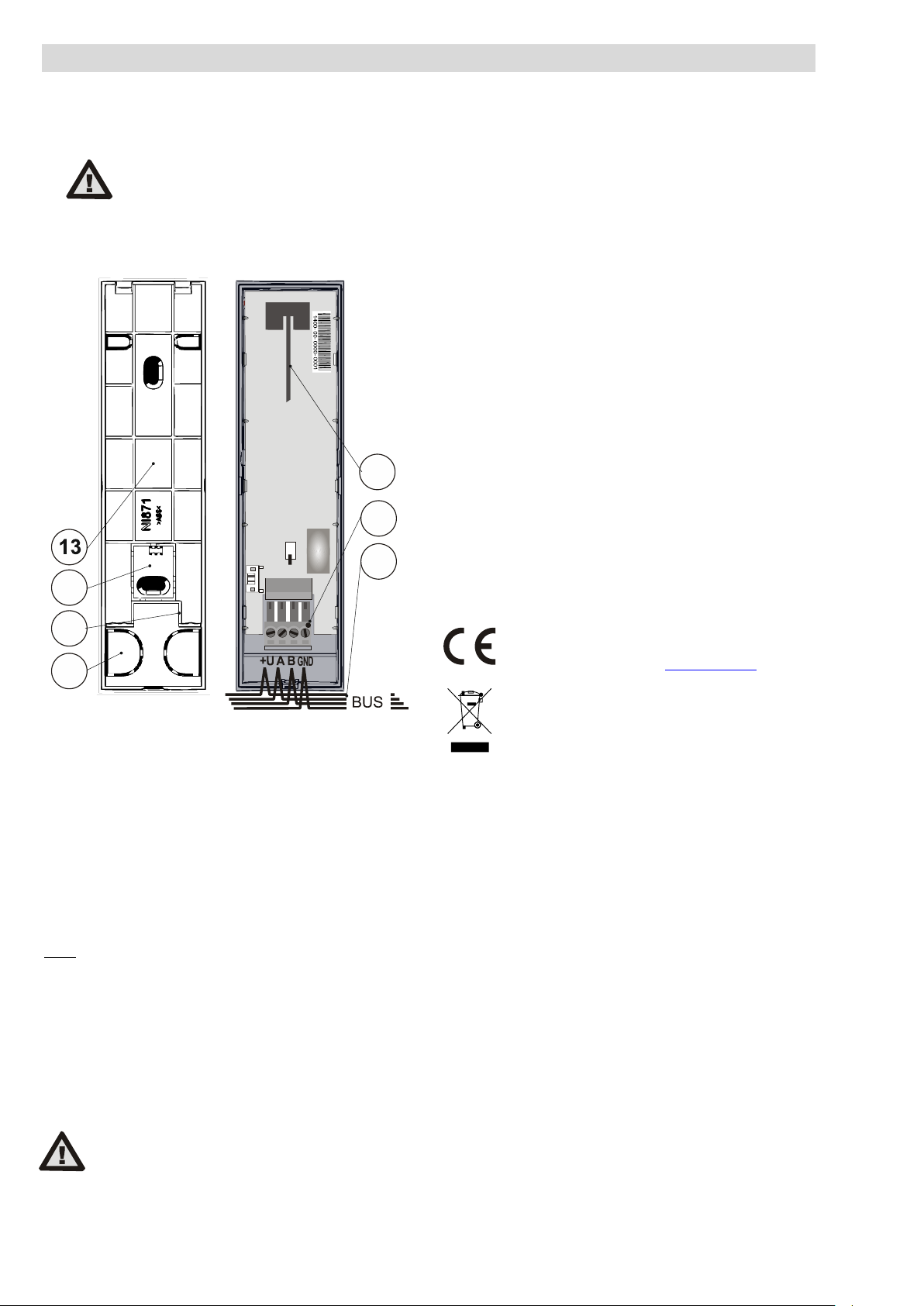
Figure 1: 1 – tamper contact; 2 – connection cable connector
After completing the whole installation in the given object, it is always
necessary to check the signal level in the Diagnostics tab in the F-Link
software. The signal level of wireless devices in the given installation
should not be less than 20 % due to the possible connection loss.
In such case it is necessary to find a more convenient place to install
the radio module or to add another radio module to the installation.
Installation of the radio module into the control
panel (A)
The PCB of the radio module can be placed into the holder directly
in the control panel. The connection to the control panel is made with
a flat cable supplied with the control panel (always at the required length
depending on the type of the control panel).
The BUS connector on the control panel PCB
is exclusively designed for the connection
of one radio module placed in the holder
in the control panel.
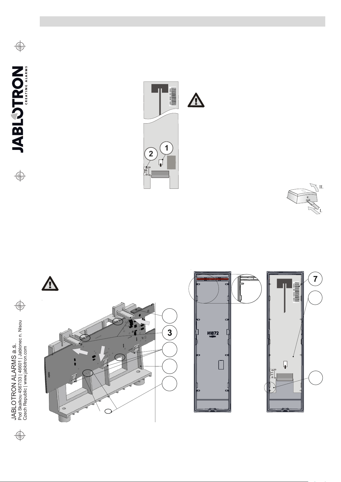
Figure 2: 2 – connection cable connector; 3 – upper holder tabs;
4 – lower inclined locking tabs; 5 – radio module holder; 6 – locking detail
1. Insert the PCB of the radio module (orientation according to Figure
2) into the holder (5) in a direction indicated by arrow I. at an angle
given by the three lower inclined locking tabs (4). Make sure that
the PCB of the radio module sits with its half-round cutouts
on the half-round tabs – see detailed locking (6). This is very
important because the next step is securing the radio module with
the upper tabs (3) in a direction indicated by arrow II. during which
the tamper contact (1) on the top side of the radio module must
be triggered.
2. Plug the connection cable (supplied with the control panel)
to the radio module connector (2) and then to the connector
of the control panel (see the installation manual of the control panel).
3. Proceed by following the Module enrollment into the system chapter
in this manual.
In case of an installation into the control
panel it is necessary to check the tamper
contact status in the Diagnostics tab in the
F-Link software (after enrolling the radio
module into the system). If the tamper
contact is active check the positioning
of the PCB in the holder.
Installation of the radio module outside
the control panel (B)
The PCB of the radio module can be installed outside the control
panel within the BUS range by placing it into the PLV-JA111R plastic
cover. The plastic cover comes with a mounting package including
labelled BUS terminals. To take out the radio module from the holder
in the control panel unplug the connection cable, release the upper tabs
(3) and take out the radio module from the holder.
1. Open the plastic cover by pressing the tab
in the rear part in the direction indicated
by the arrow I. and by tilting the front part
in the direction indicated by the arrow II.
The plastic parts of the radio module cover
will become separated.
2. Place the radio module into the front part
of he cover (orientation – indication LED up,
terminal down). We recommend holding the radio module
by the BUS connector (components of the radio module facing up),
place the left side of the radio module at an angle under the locking
tabs on the left side and then place the other side under the locking
tabs on the right side of the part of the plastic cover. The correct
position is defined by the half-round cutouts in the radio module
PCB and the guiding grooves in the inner side of the front part of the
plastic cover (9). For a proper fitting into the plastic part a slight force
must be used, it is advised to push on the label with the production
code (7) and the shielding plate (8).
Figure 3: 7 – production code; 8 – shielding plate;
9 – locking tab and guiding groove for module attachment
3. Prepare holes for the BUS cable in the bottom of the rear part (16).
Put the BUS cable through.
4. Screw on the rear part (13) including the attachment of the segment
for a tamper detection (14).