manuals.online logo
Brands
  1. Home
  2. •
  3. Brands
  4. •
  5. jablotron
  6. •
  7. Recording Equipment
  8. •
  9. jablotron JA-121T User manual

jablotron JA-121T User manual

JABLOTRON ALARMS a.s.
Pod Skalkou 4567/33 46601 Jablonec n. Nisou
Czech Republic www.jablotron.com
||
|
The JA-121T BUS RS-485 interface
The JA-121T BUS RS-485 interface 1 / 3 MNN51110
The JA-121T is a BUS component of the JABLOTRON system.
It is a universal converter which interfaces communication between
the system BUS and the RS-485 serial line and vice versa. For
example, it is suitable for instant connection of a smart home
systems thus giving you the possibility to fully use the features of
both systems. It includes galvanically separated circuits protecting
the device against up to 4kV. Data is sent during a status change
or when requested. The module is addressable and takes one
position in the system. The module should be installed by a trained
technician with a valid certificate issued by an authorised
distributor.
Installation
1. Attach the module to an appropriate place, in the range of the
JABLOTRON 100 BUS and RS-485 serial line. We recommend
using a JA-190PL installation box and utilizing a spring on the
LEARN button (5) – used as a tamper contact.
2. If the module is placed in a different box with its own tamper
protection, use the TMP contacts (3). After enrolling the module
in the control panel, you can select a type of tamper protection
(the LEARN button or the TMP contact).
3. Connect the wires to the RS-485 (6) output terminals including
the common power supply which serves to supply the serial
line.
Figure 1: 1 – BUS terminals; 2 – production code (sticker on the BUS
terminals); 3 – TMP terminal; 4 – yellow LED; 5 – LEARN (enrollment) button
(tamper – spring is included); 6 – galvanically separated RS-485 BUS output
When connecting the module to the system
BUS, always switch the power off.
4. Connect the BUS cables to the terminals (1).
5. Proceed according to the control panel installation manual.
Basic procedure:
a. When the system is switched on, the yellow LED (4) starts
flashing repeatedly to indicate that the module has not
been enrolled into the system yet.
b. Go to the F-Link software, select the required position in
the Devices tab and launch the enrollment mode by
clicking on the Enroll option.
c. Click on the option Scan/add new BUS devices, select
the JA-121T module and double-click to confirm selection –
the yellow LED indicator (4) goes off.
6. Close the cover of the installation box with the module.
Notes:
−It is possible to enroll the device by pressing the front LEARN
button (5).
−The detector can be enrolled by entering the production code
(2) in the F-Link software (or using a bar code reader). Enter all
digits located below the bar code (1400-00-0000-0001).
−If you want to remove the detector from the system, erase it
from its position in the control panel.
Terminal mode – function description
The communication of the RS-485 serial line is coded in ASCII,
speed 9600 baud, 8N1 (8 data bits, no parity, 1 stop-bit). Control is
realized by the following commands; the valid syntax is code space
command.
List of commands:
VER Returns the JA-121T module version.
HELP Returns help (valid commands and also examples of
correct syntaxes).
SET Sets selected sections: a command followed by digits
representing the sections which are to be set – each
digit always has to be separated by a space. When
sections are not specified, the system is completely
set.
SETP Sets partially selected sections: a command followed
by the digits representing the sections which are to
be set partially – each digit always has to be
separated by a space. When sections are not
specified, the system is set partially i.e. all sections
which have partial setting enabled.
UNSET Unsets selected sections: a command followed by
digits representing the sections which are to be unset
–each digit always has to be separated by a space.
When sections are not specified, the system is unset
completely.
PGON Activates PG outputs: the reference numbers of the
PG outputs you want to activate must be added after
the command. Each digit always has to be separated
by a space.
PGOFF Deactivates PG outputs: the reference numbers of
the PG outputs you want to deactivate must be
added after the command, each digit always has to
be separated by a space.
Commands SET, SETP, UNSET, PGON and PGOFF cannot
control sections or PG outputs for which the used code does not
have access rights.
STATE Returns the states of sections: a command followed
by the digits representing sections of which status
you want to check – each digit always has to be
separated by a space. When sections are not
specified, the system always returns the status of all
sections.
PGSTATE Returns the state of PG outputs: a command followed
by the digits representing the PG outputs of which
status you want to check – each digit always has to
be separated by a space. When the PG outputs are
not specified, the system always returns the status of
all PG outputs.
FLAGS Returns the active indexes in sections: the reference
numbers of the sections you want to check the
indexes for can be added – each digit always has to
be separated by a space. When sections are not
specified, the system always returns the indexes of
all sections.
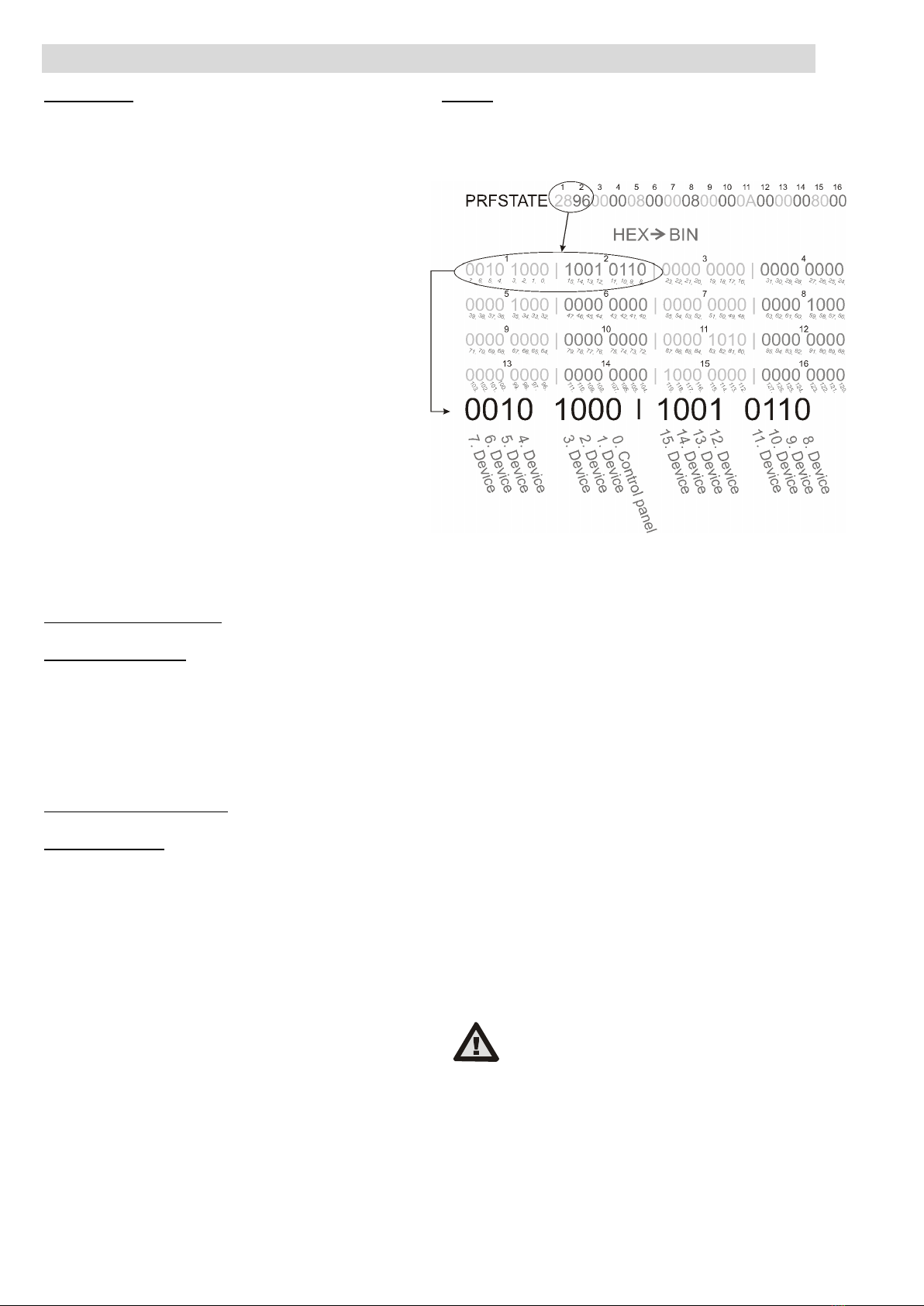
PRFSTATE Returns the status of all devices in HEX code, for
details it is necessary to convert it to BIN code
(1 – active, 0 – inactive).
Examples:
The command has to be in a specific order: valid code (with
prefix), command and additional information (list of sections which
can be set, PG outputs which can be turned off, and so on). Each
command must end with an ending character (Enter).
The entered code is used as a system user therefore it is recorded
in the event history and possible restriction linked with the user’s
code may be applied.
The JA-121T BUS RS-485 interface
The JA-121T BUS RS-485 interface 2 / 3 MNN51110
Model example:
1*1234 SET 1 2 (set sections 1 and 2)
2*4321 PGOFF 5 6 (turn off PG 5 and 6)
When the syntax has been entered correctly and if the sections
were not set before, the returned answer will be:
STATE 1 ARMED
STATE 2 ARMED
OK
According to this example it can be seen that the command has
been done successfully so sections 1 and 2 have been set and
the command was correct (OK).
If at least one section of the defined range has already been
previously set, then it sets the rest of the sections. When section
1 is already set, the returned answer will be:
STATE 2 ARMED
OK
If an entered command is found to be correct, but with invalid
authorisation, the returned answer will be:
ERROR: 3 NO_ACCESS
If the system was not able to execute any of the commands
(for example when all sections are already set) the returned answer
will be:
ERROR: 4 INVALID_VALUE
To an incorrectly entered command, the returned answer will be:
ERROR
Basic statuses of the sections:STATE <section> <status>
Example: STATE 1 READY
List of section statuses:
READY Normal mode
ARMED_PART Partially set
ARMED Set
MAINTENANCE Maintenance
SERVICE Service
BLOCKED Blocked (blocking after an alarm)
OFF Section disabled
Additional flags of the sections: <flag> <sections> ON/OFF
Example: INTERNAL_WARNING 2 ON
List of section flags:
INTERNAL_WARNING Internal siren active
EXTERNAL_WARNING External siren active
FIRE_ALARM Fire alarm
INTRUDER_ALARM Intruder alarm
PANIC_ALARM Panic alarm
ENTRY Entrance delay
EXIT Exit delay
A status of individual devices is returned after the PRFSTATE
command or automatically every 10 seconds according to the
Passive mode. A conversion of the numerical sequence from HEX
form to BIN has to be performed. This numerical sequence consists
of 14 characters for the JA-101K control panel, 32 characters for
the JA-106K control panel and 60 characters for the JA-103K and
the JA-107K control panels.
Example:
PRFSTATE 289600000800000800000A0000008000
According to the figure 2 below we can see, after conversion to
the BIN format, which devices are triggered. The active devices are
no. 3, 5, 9, 10, 12, 15, 35, 59, 81, 83 and 119.
Figure 2: Displayed layout conversion from HEX to BIN
U1-A mode – function description
(customer’s settings)
The events are converted to the set U1-A mode code, it is visible
as another ARC – concerning the radio communication module
(F-Link sets up a new way of communication). When no U1-A
device is connected and no data packets are transferred between
the system BUS and the U1-A system, a communication error is
triggered (fault of U1-A communicator).
Setting the module properties
The Internal settings option at the module position in
the Devices tab in the F-Link software opens a dialogue window
where you can set the following options for each output:
Device basic mode: Terminal / U1-A – for use with a smart
home choose Terminal.
TMP terminal: Enabled / Disabled / Inverted – factory default NC
can be changed to NO.
Motherboard button: Enrolling button / Tamper contact
Period after which a fault is triggered [min]: When an external
communication fault is triggered it generates a fault in a pre-set
time.
Connection confirmed: Every 10 s / Disabled – determines if
the communication with the RS-485 serial line is confirmed or not.
Passive mode: In the passive mode the RS-485 serial line only
receives the data, but sends them only on request (by relevant
commands).
The manufacturer only guarantees correct
functioning of the module. However, they
cannot guarantee the correct functioning
of the connected device on the serial line.
JABLOTRON ALARMS a.s.
Pod Skalkou 4567/33 46601 Jablonec n. Nisou
Czech Republic www.jablotron.com
||
|
The JA-121T BUS RS-485 interface
The JA-121T BUS RS-485 interface 3 / 3 MNN51110
Technical specifications
Input part
Power from the control panel BUS 12 V DC (9 – 15 V)
Current consumption to calculate the backup (standby) 15 mA
Maximum current consumption for cable choice 20 mA
Output part –supply from an external device
Power from an external device 12 V DC (6 – 28 V)
Nominal current load 15 mA
Maximum current load 15 mA
RS-485 operational voltage 5 V (4.75 – 5.25 V)
Input/output separation galvanically (up to 4 kV)
General
Dimensions 52 x 38 x 14 mm
Weight 15 g
Classification Environmental class II
(According to EN 50131-1)
Operational environment Indoor general
Operational temperature range -10 to +40 °C
Average operational humidity 75 % RH, non-condensing
Complies with EN 50130-4, EN 55032, EN 50581
JABLOTRON ALARMS a.s. hereby declares that
the JA-121T is in a compliance with the relevant
European Union harmonisation legislation: Directives No:
2014/30/EU, 2011/65/EU, when used as intended.
The original of the conformity assessment can be found
at www.jablotron.com – section Downloads.
Note:Di
sposing of this product correctly will help save
valuable resour
ces and prevent any potential negative
effects on human health and the environment, which
could otherwise arise from inappropriate waste handling.
Please return the product to the dealer or co
ntact your
local authority for further details of your nearest
designated collection point.

Other jablotron Recording Equipment manuals

jablotron JA-111R User manual

jablotron

jablotron JA-111R User manual

jablotron UC-280 User manual

jablotron

jablotron UC-280 User manual

jablotron UC-280 User manual

jablotron

jablotron UC-280 User manual

Popular Recording Equipment manuals by other brands

PRESONUS FIREPOD manual

PRESONUS

PRESONUS FIREPOD manual

WisyCom EXP3 installation manual

WisyCom

WisyCom EXP3 installation manual

Naigon's Electronic Creations Igniter 2 I2-R3 Setup guide

Naigon's Electronic Creations

Naigon's Electronic Creations Igniter 2 I2-R3 Setup guide

GRASS VALLEY 8964FS - instruction manual

GRASS VALLEY

GRASS VALLEY 8964FS - instruction manual

FAME Hybrid Pro DRU0039596-000 user manual

FAME

FAME Hybrid Pro DRU0039596-000 user manual

Pyle Pro PAD5 Setup guide

Pyle Pro

Pyle Pro PAD5 Setup guide

Yuan nT19AX03 Operation manual

Yuan

Yuan nT19AX03 Operation manual

Sennheiser EW 145 G2 operating instructions

Sennheiser

Sennheiser EW 145 G2 operating instructions

Nagra ARES-BB Plus manual

Nagra

Nagra ARES-BB Plus manual

Classe Audio SSP-800 Specifications

Classe Audio

Classe Audio SSP-800 Specifications

L-Acoustics L-ISA PROCESSOR Product information

L-Acoustics

L-Acoustics L-ISA PROCESSOR Product information

cymatic audio LR-16 user manual

cymatic audio

cymatic audio LR-16 user manual

illumina iSeq 100 Setup poster

illumina

illumina iSeq 100 Setup poster

Focusrite Red 8Line user guide

Focusrite

Focusrite Red 8Line user guide

Idis DD-1116 Operation manual

Idis

Idis DD-1116 Operation manual

timecode systems UltraSync BLUE user guide

timecode systems

timecode systems UltraSync BLUE user guide

Farfisa XE2920 instruction manual

Farfisa

Farfisa XE2920 instruction manual

Retekess TR102 user manual

Retekess

Retekess TR102 user manual

manuals.online logo
manuals.online logoBrands
  • About & Mission
  • Contact us
  • Privacy Policy
  • Terms and Conditions

Copyright 2025 Manuals.Online. All Rights Reserved.