jablotron JA-153E-GR User manual

JABLOTRON ALARMS a.s.
Pod Skalkou 4567/33 46601 Jablonec n. Nisou
Czech Republic www.jablotron.com
||
|
The JA-153E, JA-153E-GR, JA-153E-AN, JA-153E-WH
Wireless access module with RFID and keypad
The JA-153E, JA-153E-GR, JA-153E-AN, JA-153E-WH 1 / 2 MLU51717
The access module is a component of the JABLOTRON system.
Its modular architecture enables users to create a combination whose size of
installation perfectly meets their needs. The device should be installed by
a trained technician with a valid certificate issued by an authorised distributor.
The product is compatible with the JA-101Kx or higher control panels.
The wireless access module comprises the first control segment (1),
an RFID chip card / tag reader and keypad (4). The JA-192E, JA-192E-GR,
JA-192E-AN, JA-192E-WH segments can be used to extend the unit by
the required number of segments (the max. allowed amount is 20 on one unit).
The tilting keypad cover (6) can be removed if the user prefers permanent
access. It also works as an RFID card / tag reader.
Figure 2: 7 – connector for control
segment; 8 – production code;
9 – terminals; 10 – mini USB
connector; 11 – batteries;
12 – tamper contact
Figure1: 1 – control segment;
2 – segment buttons; 3 – backlit activation button; 4 – access module with
RFID reader; 5 – tabs for module opening;
6 – cover screws
Installation
1. Press the four tabs (5) on the sides (see figure 1) one by one and release
the module from the plastic base.
2. When installing more control segments, first remove the socket cover on
the 1st segment.
3. Remove the transparent plastic cover from the segments (by levering on
both sides of the segment near the buttons).
4. Always connect the segment wires to the connector of the previous segment
and click them into each other (we recommend coiling the wires by turning
the segment by 360° - this will prevent any possible damage to the wires
between the plastic parts). Use this method to install all the required
segments. Finally push the socket cover in.
5. Insert two 1.5 V alkaline AA batteries into the module.
6. Attach the base onto the selected place together with the segments using
screws. If more segments are required fix those onto the wall using screws
as well (use the number of screws required).
7. Connect the segment wires to the internal connector of the module (7).
8. Insert the module into the base.
9. Proceed according to the control panel installation manual.
Basic procedure:
a. There must be a JA-110R radio module installed in the control panel
with a reliable communication range to the access module.
b. When batteries are inserted, the yellow backlit activation button (3)
starts to light permanently which indicates that the module has not
been enrolled to the system yet.
c. Go to the F-Link software, select the required position in
the Devices window and launch enrollment mode by clicking on
the Enroll option.
d. Press the backlit activation button (3) – the module is thus enrolled
and the yellow LED indicator goes off (this can take a few sec).
An enrollment signal can also be sent by inserting the batteries.
10. When you have completed installation, insert descriptive labels behind the
segment transparent covers and close them, see figure 3. Label printing is
a part of the F-Link software (Devices window, at the module position –
Internal settings).
Notes:
The module can also be enrolled to the system by entering its production
code (8) in the F-Link software or using a bar code scanner. All numbers stated
under the bar code shall be entered (1400-00-0000-0001).
To comply with the EN 50131-3 norm it is necessary to fix the cover tabs (5)
by the screws from the accessories. In picture no 1 the cover tabs are
displayed and marked by the arrows.
Click!
ABCD...123
Click!
2
3
1
4
Figure 3: Insertion of a label into a control segment
Setting the properties
Go to the Devices window in the F-Link software. When you are at
the module position, use the Internal settings option. The particular unit is
displayed and it is possible to set its properties. Internal settings is separated into
2 basic tabs: Segments and Settings.
It is possible to set the required functions for individual segments (control of
sections, section status signalling, alarm triggering, PG output control, PG output
status signalling, etc.). More details are available in the F-Link software.
3rd optional setting tab Common segment – settings and function description
A common segment (up to 2 of them allowed on one keypad unit) simulates
the simultaneous pressing of several segments which are placed on this module
and which control sections. In the Segments tab select the specific segment
function called Common segment A (B). Then select the segments which will be
operated en bloc in the new tab Common segment.
Note:A module has to be equipped with a minimum of 3 segments otherwise this
function can not be used.
The selected sections will all be set / unset after pressing a button on the common
segment.
If the states of the segments which are operated by the common segment are
mixed, then only the segments that need changing will be set / unset.
If partial setting is enabled for some segments, then the common segment
respects this: 1st press = partially setting, 2nd press = full setting. It is not suitable to
combine a common segment with a common section
The indication of the common segment is: all segments unset = green, some set
(partially set) = yellow, all sections fully set = red.
In the Settings tab you can set all other module functions like acoustic signalling,
backlight intensity, RFID reader mode, optical and acoustic indication, etc. Details
related to settings can be found in the installation manual of the control panel and of
course in the tooltips displayed by the F-Link software.
Battery Power save mode
The module saves its energy by shutting down the optical indication of system
status, module backlight and the RFID reader after 8 sec when the button, segment
or keypad cover have been pressed. The module still keeps communication with
the control panel and it can signal for example: an entrance delay. Complete waking
up is done when you press the cover of the module, or by pressing of any button.
Alternative power
The module can be powered from an external 12 V DC power supply via the
PWR and GND terminals. The DE 06-12 power supply can be used.
It has the advantage of hidden installation. The module does not enter battery
power mode if external power is used. It permanently communicates with
the control panel and it indicates the system status according to
the Devices / Internal settings. Leave the batteries inside the module.
When the mains power is cut off, the module will work from the batteries.
Connection of an external door detector
The module has an input terminal for external door detector connection.
The input (IN) reacts to disconnection from the common ground. The reaction
of this input is delayed and is linked to the module address. The input has
a status reaction.

The JA-153E, JA-153E-GR, JA-153E-AN, JA-153E-WH
Wireless access module with RFID and keypad
The JA-153E, JA-153E-GR, JA-153E-AN, JA-153E-WH 2 / 2 MLU51717
Battery replacement
The module automatically checks the status of the batteries. When Low Batt
status is reported, then the batteries should be changed within 2 weeks. Before
changing the batteries, system must be firstly switched to SERVICE mode,
otherwise a tamper alarm will be triggered.
Note: For the best possible operation we strongly recommend using only
batteries supplied by Jablotron’s authorized distribution (avoid usage of so called
no-name batteries).
Unit modifications
If you need to change the segments (add or take out), release them by
levering on both sides of the segment near the buttons. When you have
finished changing the amount of segments the new JA-192E, JA-192E-GR,
JA-192E-AN, JA-192E-WH are not always immediately visible in the F-Link
software. For synchronization, click on the Upload button.
Note: If there is a request to modify the module hardware, always remove
the batteries and disconnect the external power supply.
Optical indication
Activation button – indicates the system status. No light – sleep mode, green
light – everything OK, green flashes – authorisation performed, red flashes – alarm,
yellow light – fault / not enrolled to the system, yellow double flash – Service mode.
Note: The activation button doesn´t indicate module tamper activation, even
the INP input, in Service mode.
Segments – don´t indicate when Service mode is entered or when
the segment has the function None. The optical indication logic of a PG segment
can be inverted.
Module can be preset to the following 6 indication levels:
1. Indicates permanently – Wireless modules indicate permanently only if an
external power supply is connected. Without an external power supply,
it indicates the same as option 2. When the mains is restored module again
indicates permanently.
2. Section / PG status change on keypad – the module indicates when
the section / PG status has been changed. The status change is indicated
on the specific segment. Entrance delays and alarms are indicated by
the whole module.
3. Section / PG status change on segment – the module indicates when
a section / PG output status has been changed. A segment status change,
an entrance delay and an alarm is indicated on a specific segment.
4. Segment status change on keypad – The module indicates when
the status of a segment has been changed (setting, unsetting, PG ON, PG
OFF). The change of the status is indicated only on the specific segment.
5. Entrance delays / alarms on segment – the module indicates
entrance delays and alarms on a specific segment.
6. Wake-up by pressing – the module optically and acoustically indicates
after the front cover has been opened and also when a button or
segment has been pressed. This setting ensures a maximum battery
lifetime.
Acoustic indication
It can be set regardless of the keypad’s optical indication and sleep mode.
The module can indicate entrance / exit delays or alarms. During valid
authorization (by user code or RFID card), acoustic indication of exit delay is
supressed. By pressing the indication button the module is muted
permanently. Entrance delays and alarms are indicated until their times expire,
but only if the activation button is not pressed.
FW upgrade
1. Upgrades can only be done by a Service technician and by F-Link
software.
2. Start F-Link in Offline mode and open the appropriate installation
database.
3. Open the module by pressing on the tabs (5), remove the batteries and
any possible external power supply.
4. Connect the miniUSB cable to the USB port on the PC. The miniUSB
cable is not in the accessories of the module, control panel or any other
device. You can use the cable from the JA-190T card reader.
Caution:We strictly recommend connecting the USB cable straight to
the PC, connection via a USB HUB can reduce the reliability).
5. While keeping the button (3) pressed, connect the miniUSB cable to the
connector on the module (10), and keep holding the button (3). Switching
to the firmware upgrading mode is indicated by the backlit activation
button flashing green and yellow. Now you can release the button (3).
6. Then continue as if you are doing an upgrade via F-Link software:
Control panel → Upgrade Firmware → choose the upgrade file pack
(it is a part of the F-Link installation pack, or it can be independently
published for downloading, file type *.fwp)
7. F-Link shows a window with a device listing, select the USB (typically at
the first position).
8. Then press OK and perform the upgrade for the selected device.
9. Disconnect the miniUSB cable, reinsert the batteries and reassemble
the module.
10. Check the module via F-Link, Devices/Internal settings. According to
the changes which have been done during the upgrade, previous settings
might stay or settings could be erased to default. When a reset has been
done you can reload the previous settings by the Import button and
restore them with no negative influence on the new firmware.
11. When the FW upgrade has been done, the main menu could be
expanded. In this case the new options are set to default. Check their
settings and adjust according to user requirements.
12. Perform a last check and try out the functions by some tests.
Technical specifications
Power supply: 2x alkaline batteries, type: AA (LR6, 1.5V/ 2.45Ah)
Please note: Batteries are not included.
Typical battery lifetime: 1–2 Years
Low Battery Treshold: < 2 V
Quiescent current consumption: 20 μA
Maximal current consumption: 40 mA
Each additional control segment: 2.5 mA
Communication range: 868.1 MHz, JABLOTRON protocol
Maximum radio-frequency power (ERP): 15 mW
Communication range: cca 200 m (open area)
RFID frequency: 125 kHz
Maximum RFID magnetic field strength:-5.4 dBμA/m (measured at 10 m dist.)
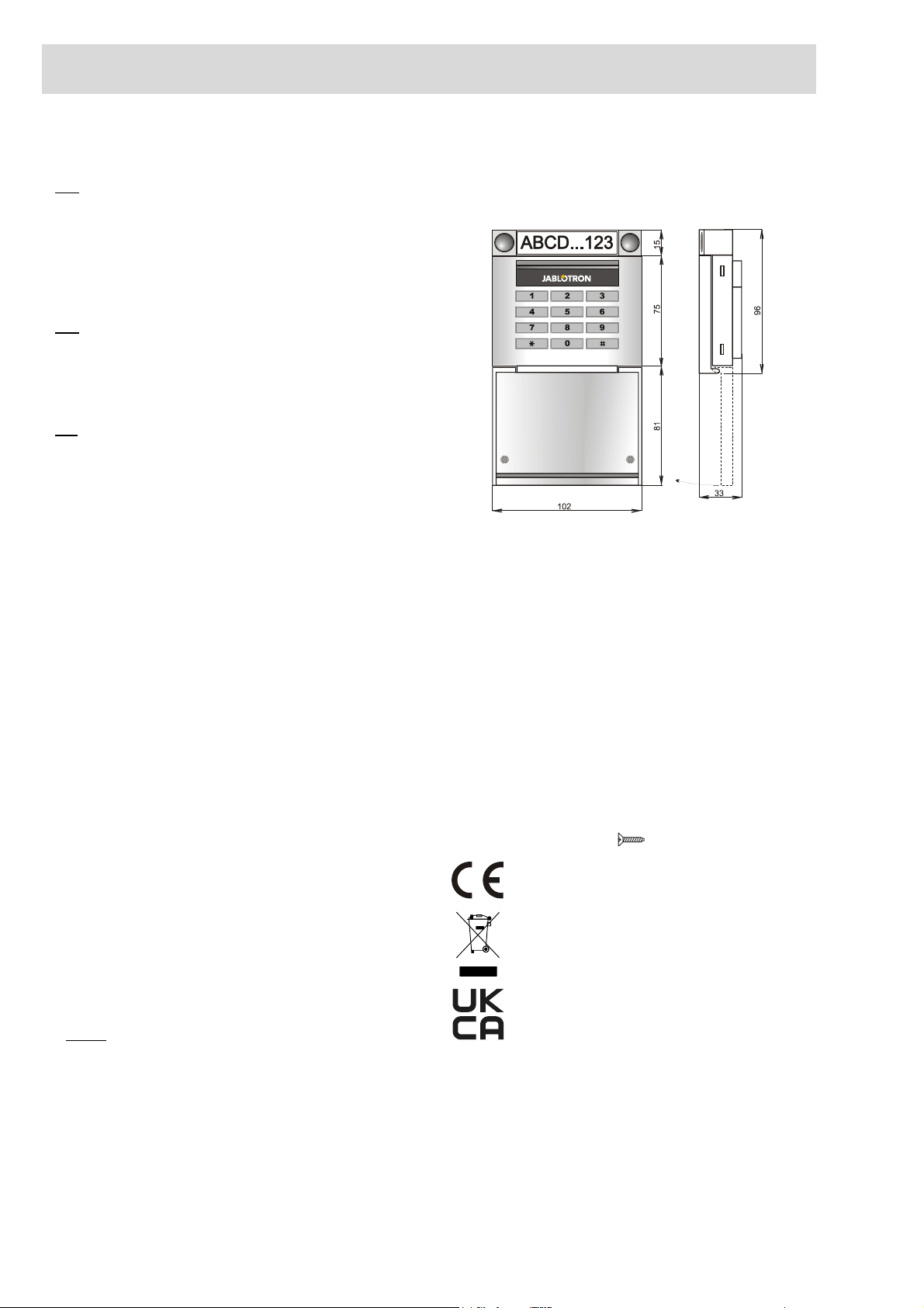
Dimensions: 102 x 96 x 33 mm
Weight (without batteries): 160 g
Classification Security grade 2/Environmental class II (EN 50131-1)
Environment indoor general
Operating temperature range -10 °C to +40 °C
Average operational humidity 75 % RH, w/o condensation
Certification body Trezor Test s.r.o. (no. 3025)
In compliance with ETSI EN 300 220-1,-2, ETSI EN 300 330,
EN 50130-4, EN 55032, EN 62368-1, EN 50581,
EN 50131-1, EN 50131-3, EN 50131-5-3, EN 50131-6
Operating conditions according to general authorization ERC REC 70-03
Recommended screw 4 x ø 3.5 x 40 mm (countersunk head)
JABLOTRON ALARMS a.s. hereby declares that the JA-153E, JA-153E-GR,
JA-153E-AN, JA-153E-WH
is in a compliance with the relevant Union
harmonisation legislation: Directives No: 2014/53/EU, 2014/35/EU,
2014/30/EU, 2011/65/EU. The original of the conformity assessment can be
found at www.jablotron.com - Section Downloads.
Note: Disposing of this product correctly will help save valuable resources and
prevent any potential negative effects on human health and the environment,
which could otherwise arise from inappropriate waste handling. Please return
the product to the dealer or contact your local authority for further details of
your nearest designated collection point.
This manual suits for next models
3
Other jablotron Wireless Access Point manuals
Popular Wireless Access Point manuals by other brands

TRENDnet
TRENDnet TEW-455APBO - 9dBi High Power Wireless Outdoor PoE Access... user guide

TP-Link
TP-Link TL-WA901N user guide

Compex
Compex NetPassage WP18 1A Quick install guide

peplink
peplink Pepwave AP One Series user manual

LevelOne
LevelOne WAB-3002 specification

D-Link
D-Link NUCLIAS CONNECT user guide