JACT AT580 Series User manual

AT580 User's Manual
1
Preface
Thank you for purchasing the AT580 series inverter developed by Wuxi JACT
Electric Co., Ltd.
The AT580 series inverter is a general-purpose high-performance current vector
control inverter. It can implement the control of asynchronous motor. It is used to
drive various automation production equipment involving textile, paper-making,
wire drawing, machine tool, packing, food, fan and pump.
This manual describes the correct use of the AT580 series inverter, including
selection, parameter setting, commissioning, maintenance & inspection. Read and
understand the manual before use and forward the manual to the end user.

AT580 User's Manual
2
Note
The drawings presented in this instructions are sometimes
shown without covers or protective guards. Always replace the
equipment’s cover or protective guard as specified first, and then
operate the products in accordance with the instructions.
The drawings in the manual are shown for description only and
may not match the product you purchased.
The instructions are subject to change, without notice ,due to
product upgrade, specification modification as well as efforts to
increase the accuracy and convenience of the manual.
Conduct our agents or customer service center if you have
problems during the use.
Service Hotline:0510-85380261
Fax:0510-85380361
24-hour technical service line:86 13306170378 and 86 13306170877

AT580 User's Manual
3
Contents
Preface..................................................................................................................1
Contents.................................................................................................................3
Chapter 1 Safety Information and Precautions ...................................................3
1.1 Security Information......................................................................................................... 3
Chapter 2 Product Information.............................................................................6
2.1 Designation Rules............................................................................................................ 6
2.2 Nameplate........................................................................................................................ 6
2.3 AT580 Models and Technical Data .................................................................................. 6
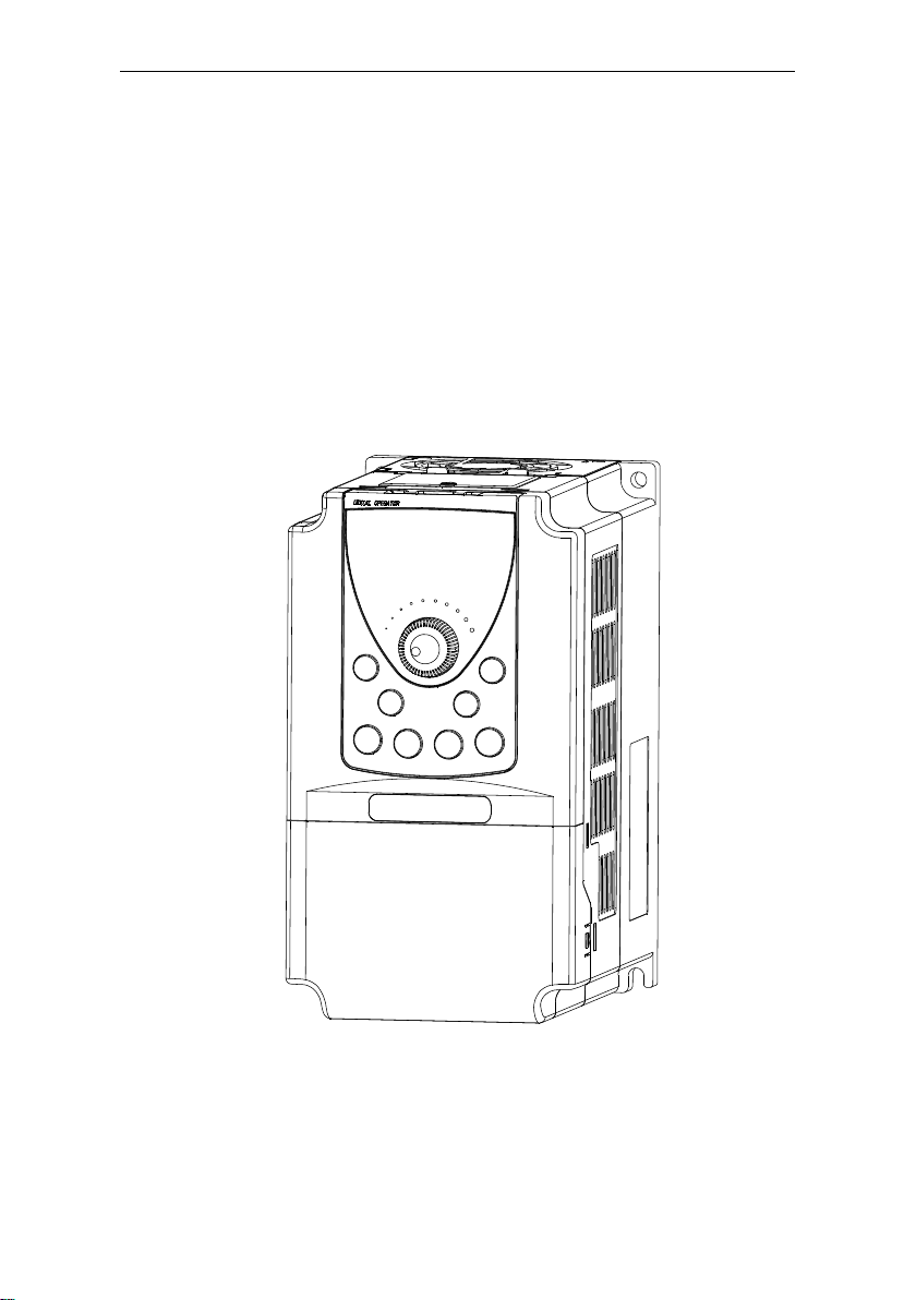
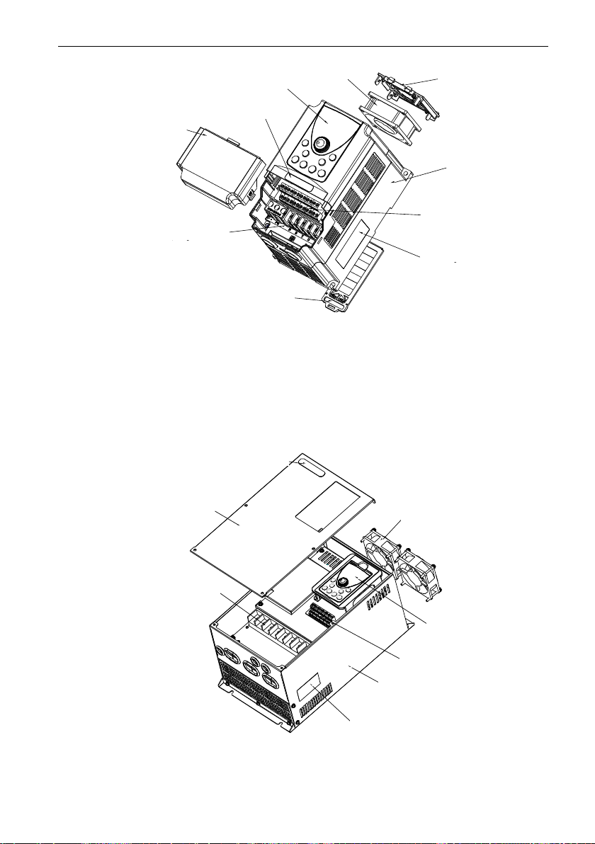
2.4 Product Description of Each Part .................................................................................... 8
2.5 Technical Specifications................................................................................................... 9
2.6 Appearance and Installation Size of the Keyboard ....................................................... 13
2.7 Appearance and Hole Size of the Keyboard Tray ......................................................... 13
2.8 Appearance and Installation Size of the Double Row Keyboard................................... 14
2.9 Appearance and Hole Size of the Double Row Keyboard Tray .................................... 14
Chapter 3 Mechanical Installation......................................................................15
3.1 Installation Environment ................................................................................................ 15
3.2 The Disassembly of The Cover Plate............................................................................ 16
Chapter 4 Electrical Installation .........................................................................17
4.1 Electrical Installation...................................................................................................... 17
4.2 Description of Peripheral Electrical Devices.................................................................. 18
4.3 Peripheral Electrical Components Selection Guidance................................................. 18
4.4 Selection of Braking Unit and Braking Resistor ............................................................ 19
4.5 Wiring Method................................................................................................................ 21
Chapter 5 Operating and Display .......................................................................28
5.1 Operation and Display Interface.................................................................................... 28
5.2 Function Indicator Description....................................................................................... 29
5.3 Keyboard Button Description Table............................................................................... 29
5.4 Viewing and Modifying Function Codes ........................................................................ 29
5.5 Selecting Menu Mode.................................................................................................... 30
Chapter6 Function Parameter List .....................................................................31
Chapter7 Description of Function Codes ..........................................................65
Group F0 :Basic Parameters ............................................................................................... 65
Group F1: Motor parameters ............................................................................................... 70
Group F2:Input Terminal...................................................................................................... 72
Group F3: Output Terminals ................................................................................................ 79
Group F4: Auxiliary Functions.............................................................................................. 83
Group F5: Vector Control Parameters................................................................................. 91

AT580 User's Manual
2
Group F6: V/F Control Parameters...................................................................................... 93
Group F7: Start/Stop Control ............................................................................................... 96
Group F8: Operation Panel and Display.............................................................................. 99
Group F9: Fault and Protection ......................................................................................... 101
Group FA: Process Control PID Function.......................................................................... 107
Group FB: Swing Frequency, Fixed Length ,Count and Torque Control Parameters........111
Group FC: Multi-Reference and Simple PLC Function Parameters ..................................114
Group FD: User-defined Parameters..................................................................................117
Group FE:Quick Menu Parameters ....................................................................................117
Group P0:Analog Four Points Offset Parameters ..............................................................117
Group P1:Analog Calibration Parameters..........................................................................119
Group H0: Monitoring Parameters..................................................................................... 120
Chapter 8 Special function of spinning frame.................................................123
Chapter 9 Maintenance and Troubleshooting..................................................125
9.1 Routine Repair and Maintenance of the AT580........................................................... 125
9.2 Warranty Agreement.................................................................................................... 126
9.3 Faults and Solutions .................................................................................................... 126

AT580 User's Manual
3
Chapter 1 Safety Information and Precautions
In this manual, Safety cautions are divided into two types:
DANGER: indicates that failure to comply with the notice will result in severe
personal injury or even death.
WARNING: indicates that failure to comply with the notice will result in personal
injury or property damage.
Read this chapter carefully so that you have a thorough understanding, and perform all
operations such as installation, commissioning or maintenance by following the notices in this
chapter. JACT will assume no liability or responsibility for any injury or loss caused by
improper operation.
1.1 Security Information
Before installation
Danger
●The AC drive is designed to the speed control of asynchronous motor,
any other uses may cause damage of the AC drive or result in a fire.
●The AC device shouldn’t be applied simply in medical devices or other
situations directly related to personal safety.
Checking
Warning
● Do not install the AC device if you find component missing or damage
upon unpacking.
During installation
Warning
●Handle the AC device with care during transportation to prevent
damage to the AC device.
●Install the AC device on incombustible objects such as metal, and keep
it away from combustible materials. Failure to comply may result in a fire.
●Do not drop wire end or screw into the AC drive. Failure to comply
will result in damage to the AC drive.
●If the AC device is installed in cabinet, fan and ventilation opening
should be set for rejection of heat.
Wiring
Danger
●Wiring must be performed only by qualified personnel under
instructions described in this manual. Failure to comply may result in

AT580 User's Manual
4
unexpected accidents.
●Ensure that the power supply is cut off before wiring. Failure to
comply may result in electric shock.
●Tie the AC drive to ground properly according to the requirements.
Failure to comply may result in electric shock.
●Do not touch the terminals of the major loop, and make sure the major
loop wires are not connect to the shell. Failure to comply may result in
electric shock.
●The leakage current of the AC drive is greater than 5 mA and the
specific value is determined by the working condition. The AC drive and
motor must connect to the ground properly for safe.
Warning
●Never connect the power cables to the output terminals(U,V,W) of the
AC drive. Failure to comply will result in damage to the AC drive.
●Never connect LC/RC noise filter for phase advance, like capacitance,
to the output terminals. Failure to comply will result in damage to the AC
drive.
●Ensure that the power phases and voltage are match the data on
nameplate. Failure to comply may result in damage to the AC drive.
●The major loop and control loop should be wired separately or crossly.
Failure to comply may result in disturb of the control signal.
●The cable for major loop should be shielded by insulating bush.
●Input or output reactor is recommended when the input or output cable
is longer than 100 meters. Failure to comply may result in damage to the AC
drive or the motor.
Running
Danger
● Cover the AC drive properly befor power-on and never open the cover
plate with power. Failure to comply may cause electric shock.
●Isolation measures should be adopted for machine with automatic reset
of fault or start after the power failure. Failure to comply may result in
personal injury.
●Never touch the terminals when the AC drive is on power, even it’s on
stop state. Failure to comply will result in electric shock.
●Never reset the alarm or warning before cutting off the running
command. Failure to comply may result in personal injury.
Warning
●Do not start/stop the AC drive by turning the contactor ON/OFF.
Failure to comply will result in damage to the AC drive.
●Ensure the motor and machine are in permitted useful range before
running. Failure to comply will result in damage of machine.
●Do not touch the fan nor the discharging resistor, otherwise you may
get burnt.
●Do configuring the mechanical lock device in using of elevator
equipment.
●Do not change the default factory settings of the AC drive. Failure to

AT580 User's Manual
5
comply will result in damage to the AC drive.
●Do setting the interlock with two contactors which are using in
switching of VF/WF.
Maintenance
Danger
●Do not repair or maintain the AC drive at power-on. Failure to comply
will result in electric shock.
●Ensure power-off before removing the cover plate.
●Repair or maintain the AC drive only ten minutes after the AC drive is
powered off or the charging LED is off. Otherwise, the residual voltage in the
capacitor will result in personal injury.
●Repair or maintenance of the AC drive can be performed only by
qualified personnel. Failure to comply will result in personal injury or damage
to the AC drive.
●Do not touch the components with your hands. Failure to comply will
result in static electricity damage.
Other
Warning
●Self-reliant rebuilding is forbidden. Failure to comply will result in
personal injury.

AT580 User's Manual
6
Chapter 2 Product Information
2.1 Designation Rules
Figure 2.1 Designation rules
2.2 Nameplate
010103713102201
MODEL: AT580-T3-011G/015P
INPUT: 3PH AC 380V 26A 50Hz/60Hz
OUTPUT1: 3PH AC 0~380V 25A 0~300Hz
OUTPUT2: 3PH AC 0~380V 32A 0~300Hz
S/N:
Wuxi JACT Electric Co. , Ltd.
Figure 2.2 Data brand
2.3AT580 Models and Technical Data
Table 2-1 AT580 models and data
inverter types
Power
capacity
(kVA)
Input
current
(A)
Output
current(A)
Adapter motor
(power)(horsepower)
(kW) (HP)
Single-phase power supply: 220V,50/60Hz
AT580-S2-0R4GB
1
5.4
2.3
0.4
0.5
AT580-S2-0R7GB
1.5
8.2
4
0.75
1
AT580-S2-1R5GB
3
14
7
1.5
2
AT580-S2-2R2GB
4
23
9.6
2.2
3
AT580
-

AT580 User's Manual
7
Three-phase power supply: 380V,50/60Hz
inverter types
Power
capacity
(kVA)
Input
current
(A)
Output
current(A)
Adapter motor
(power)(horsepower)
(kW) (HP)
AT580-T3-0R7G/1R5PB
1.5
3.4
2.1
0.75
1
AT580-T3-1R5G/2R2PB
3
5
3.8
1.5
2
AT580-T3-2R2G/4R0PB
4
5.8
5.1
2.2
3
AT580-T3-4R0G/5R5PB
5.9
10.5
9
3.7
5
AT580-T3-5R5G/7R5PB
8.9
14.6
13
5.5
7.5
AT580-T3-7R5G/011PB
11
20.5
17
7.5
10
AT580-T3-011G/015PB
17
26
25
11
15
AT580-T3-015G/018PB
21
35
32
15
20
AT580-T3-018G/022PB
24
38.5
37
18.5
25
AT580-T3-022G/030PB
30
46.5
45
22
30
AT580-T3-030G/037P
40
62
60
30
40
AT580-T3-037G/045P
57
76
75
37
50
AT580-T3-045G/055P
69
92
91
45
60
AT580-T3-055G/075P
85
113
112
55
75
AT580-T3-075G/090P
114
157
150
75
100
AT580-T3-090G/110P
134
180
176
90
125
AT580-T3-110G/132P
160
214
210
110
150
AT580-T3-132G/160P
192
256
253
132
200
AT580-T3-160G/185P
231
307
304
160
210
AT580-T3-200G/220P
250
385
377
200
270
AT580-T3-220G/250P
280
430
426
220
300
AT580-T3-250G/280P
355
468
465
250
335
AT580-T3-280G/315P
396
525
520
280
380
AT580-T3-315G/355P
445
590
585
315
420
AT580-T3-355G/400P
500
665
650
355
470
AT580-T3-400G/450P
565
785
725
400
530
AT580-T3-450G
630
883
820
450
600
Customized for AT580-T3-500G and larger

AT580 User's Manual
8
2.4 Product Description of Each Part
下面盖
导轨卡块
(仅2.2KW 以下有)
外壳
变频器铭牌
功率端子
控制端子
键盘
风扇 风扇罩
公司标签
Figure 2.3 Name of components for plastic shell
功率端子
控制端子
变频器铭牌
键盘
风扇
外壳
面壳
公司标签
Figure 2.4 Name of components for metal plate shell
Fan
Fan cover
Key board
Low cover
Control terminal
Shell
Nameplate
nameplate
Power terminal
terminal
Guide card block
Equipped below 2.2kw
Power terminal
Fan
Key board
Company label
Control terminal
Nameplat
e
nameplate
Shell
Surface of the shell
Company label

AT580 User's Manual
9
2.5 Technical Specifications
Table 2-2 Technical specifications of the AT580
Project
Specification
Standard
functions
Maximum
frequency
0~320Hz
Carrier
frequency
0.5kHz~16.0kHz
The carrier frequency is automatically adjusted based on the
temperature
Input frequency
resolution
Digital setting:0.01Hz
Analog setting:maximum frequency×0.025%
Control mode
Voltage/Frequency(V/F) control
Switching vector control (SVC)
Forward vector control (FVC)
Startup torque
G type: 0.5Hz/150% (SVC); 0Hz/180% (FVC)
P type: 0.5Hz/100%
Speed range
1:100(SVC)
1:1000(FVC)
Speed stability
accuracy
±0.5%(SVC)
±0.02%(FVC)
Torque control
accuracy
±5% (FVC)
Overload
capacity
G type: 60s for 150% of rated current and 3s for 180% of
rated current
P type: 60s for 120% of rated current and 3s for 150% of
rated current
Torque boost
Automatic torque boost
Manual torque boost 0.1%~30.0%
V/F curve
Straight-line V/F curve
Multi-point V/F curve
Square V/F curve
Ramp mode
Straight-line ramp
S-curve ramp
Four groups of acceleration/deceleration time with the range
of 0.0–6500.0s
DC braking
DC braking frequency: 0.00 Hz to maximum frequency
Braking time: 0.0–100.0s
Braking action current value: 0.0%~100.0%
JOG control
JOG frequency range: 0.00–50.00 Hz
JOG acceleration/deceleration time: 0.0–6500.0s
Simple PLC,
multi-speed
running
It implements up to 16 speeds via the simple PLC function or
combination of DI terminal states.
Built-in PID
It implements the closed-loop process control system easily.
Auto voltage
regulation
(AVR)
It can keep constant output voltage automatically when the
mains voltage changes.

AT580 User's Manual
10
Project
Specification
Standard
functions
Overvoltage/
Overcurrent stall
control
The current and voltage are limited automatically during
the running process so as to avoid frequent tripping due to
overvoltage/overcurrent.
Rapid current
limit
It decreases the overcurrent faults to the minimum and
ensures normal running of the AC drive.
Torque limit and
control
It can limit the torque automatically and prevent frequent
over current tripping during the running process.
Torque control can be implemented in the CLVC mode.
Individua-
lized
functions
High
performance
Control of asynchronous motor is implemented through the
high-performance current vector control technology.
Run
continuous in
instantaneous
power failure
The load feedback energy compensates the voltage
reduction so that the inverter can continue to run for a short
time.
Timing control
Time range: 0.0–6500.0 minutes
RS485 bus
support
Modbus-RTU protocol
Running
Running
command
source
• Operation panel control
• Terminal control
• Communication control
You can perform switch over between these sources in
various ways.
Frequency
source
There are a total of five frequency sources, such as digital
setting, analog voltage setting, analog current setting, pulse
setting and communication setting,
You can perform switch over between these sources in
various ways.
Auxiliary
frequency
source
There are a total of five frequency sources, such as digital
setting, analog voltage setting, analog current setting, pulse
setting and communication setting,
It can implement fine tuning of auxiliary frequency and
frequency synthesis.
Input terminal
5 digital input (DI) terminals, X5 supports up to 100 kHz
high-speed pulse input;
2 analog input (AI) terminals, AI1 only supports 0–10 V
voltage input and AI2 supports 0–10 V voltage input or
0–20 mA current input.
Output
terminal
1 high-speed pulse output terminal (open-collector) that
supports 0–100 kHz square wave signal output
1 digital output (DO) terminal
2 relay output terminals(One is factory default, the other is
optional)
2 analog output (AO) terminals that supports 0–20 mA
current output or 0–10 V voltage output.

AT580 User's Manual
11
Project
Specification
Display and
keyboard
LED display
Display parameters (three display modes: Basic mode,
Quick menu mode, Non-factory value mode).
Protection
function
Motor short-circuit detection at power-on, input/output
phase loss protection, overcurrent protection, over voltage
protection, under voltage protection, overheat protection
and overload protection.
Optional parts
Braking unit, I/O extension card, RS485 communication
card, differential input PG card, OC input PG card, sin/cos
PG card.
Environ-
ment
Installation
location
Indoor, free from direct sunlight, dust, corrosive gas,
combustible gas, oil smoke, vapour, drip or salt.
Altitude
Lower than 1000 m (de-rated if higher than 1000 m)
Ambient
temperature
-10°C to +50°C
Humidity
Less than 95%RH, without condensing
Vibration
Less than 5.9 m/s2 (0.6 g)
Storage
temperature
-20℃~+60℃
Appearance and installation dimensions(mm)
a) Wall-mounted mounting dimensions
W1
W
HH1
D1
D
Figure2-5 Plastic shell mounting dimensions

AT580 User's Manual
12
W1
W
H1 H
D1
D
Figure2-6 Metal plate mounting dimensions
Table 2-3 Physical dimensions and mounting dimensions of the AT580 (mm)
Model
Location of holes
Dimensions
Diameter
of hole
W1
H1
H
W
D1
D
AT580-S2-0R7GB
71.5
121.5
132
80
105.5
114.6
φ4.5
AT580-S2-1R5GB
AT580-S2-2R2GB
88.4
168.4
180
100
152
159
φ5.5
AT580-T3-0R7G/1R5PB
AT580-T3-1R5G/2R2PB
AT580-T3-2R2G/4R0PB
AT580-T3-4R0G/5R5PB
118.4
224.5
236
130
163.5
170.5
φ5.5
AT580-T3-5R5G/7R5PB
AT580-T3-7R5G/011PB
141
243
260
155
175
182
φ7
AT580-T3-011G/015PB
AT580-T3-015G/018PB
160
440
460
230
212
220
φ10
AT580-T3-018G/022PB
AT580-T3-022G/030PB
AT580-T3-030G/037P
190
555
575
305
215
224
φ10
AT580-T3-037G/045P
AT580-T3-045G/055P
230
643
670
390
290
298
φ12
AT580-T3-055G/075P
AT580-T3-075G/090P
260
717
738
410
285
294
φ10
AT580-T3-090G/110P
AT580-T3-110G/132P
320
780
810
455
316
325
φ12
AT580-T3-132G/160P
AT580-T3-160G/200P
400
925
960
630
416
425
φ14
AT580-T3-200G/220P

AT580 User's Manual
13
Model
Location of holes
Dimensions
Diameter
of hole
AT580-T3-220G/250P
480
1005
1040
650
411
420
φ14
AT580-T3-250G/280P
AT580-T3-280G/315P
AT580-T3-315G/355P
600
1252
1300
815
427
436
φ14
AT580-T3-355G/400P
AT580-T3-400G/450P
AT580-T3-450G
Customized for AT580-T3-500G and larger
2.6 Appearance and Installation Size of the Keyboard
60 14.3 21.3
96
60.5
38.85.5
29.3
Figure 2.7Appearance and installation size of the keyboard
2.7 Appearance and Hole Size of the Keyboard Tray
2-R12
键盘托盘尺寸 托盘开孔尺寸
(也可开方孔 115mm*67mm)
121.2
74.2 15.8
115
67
101.9
R12.5
2-R5
Figure 2.8 Keyboard tray appearance and hole size map
Control cabinet back
Fix with the bottom screw

AT580 User's Manual
14
2.8 Appearance and Installation Size of the Double Row Keyboard
60 14.3
21.1
32.7
77.2
5.2 39.1
116
Figure 2.9 Appearance and installation size of the double row keyboard
2.9 Appearance and Hole Size of the Double Row Keyboard Tray
121.9
2-R5
2-R12
R12.5
66
(135)
托盘开孔尺寸
(也可开方孔129.5mm*66mm)
74.2
141.2
15.8
托盘尺寸
Figure 2.10 the Double row keyboard tray appearance and hole size map

AT580 User's Manual
15
Chapter 3 Mechanical Installation
3.1 Installation Environment
1) Environmental temperature: the ambient temperature has a great influence, should
always keep the environment temperature under the inverter’s allowed temperature range (-10
to 50 Degrees Celsius).
2) Install the inverter on the surface of an incombustible object, and ensure that there is
sufficient space around for heat dissipation. Install the inverter vertically on the support using
screws.
3) The vibration should be less than 0.6 g and the inverter should be installed far away
from the punching machine or the like.
4) The mounting location should be free from direct sunlight, high humidity and
condensation.
5) The mounting location should be free from corrosive, explosive and combustible gas.
6) The mounting location should be free from oil dirt, dust and metal powder.
AT500
隔热导流板
AT500
Figure 3.1 AT580 inverter installation diagram
Annotation: The size of “A”may not be considered when the inverter power is not greater
than 22KW, but longer than 50mm when the inverter power is over 22KW.
Clearance Requirements
0.75KW-22KW
A>10mm
B>100mm
30KW-37KW
A>50mm
B>200mm
45KW-75KW
A>50mm
B>200mm
90KW-630KW
A>50mm
B>300mm
Insulation guide plate
AT580
AT580
It should be installed vertically upward
Cold air
Hot air
AT580

AT580 User's Manual
16
Annotation: The heat guide plate is needed when the inverters are installed vertically next
to each other.
Attention matters for heat dissipation of mechanically mounting:
1) The inverter should be installed vertically but not inverted for heat distribution. Side by
side installing is highly considered for many inverters install in one cabinet. The heat
guide plate should be set in vertical install situation, like Figure 3.1.
2) The installation space should follow Figure3.1 to ensure radiation space. But other
parts heat dissipation should be considered when layout.
3) The mounting bracket must be flame retardant material.
4) The installation way of heat sink outside the cabinet is considered in the occasion of
metal dust using. And the sealed cabinet space should be as large as possible.
3.2 The Disassembly of The Cover Plate
挂钩
1.左右对称向内侧用力
压挂钩使挂钩松脱 2.抓紧盖板下端并
往上旋转抽出
Figure 3.2 Disassembly of the cover plate (plastic shell)
2.抓紧盖板下端并
往上旋转抽出
1.用螺丝刀卸下 2颗
面板上的螺钉
Figure 3.3 Disassembly of the cover plate (metal plate shell)
2. Catch the edge of
the cover and lift it
1. Press inward symmetrically to
disconnect the hook from the hook
slot
2. Catch the edge of
the cover and lift it
1. Loosen the 2
screws

AT580 User's Manual
17
Chapter 4 Electrical Installation
4.1 Electrical Installation
Figure 4.1 Peripheral electrical devices
●Do not install capacitors or surge suppressor in the output side of the inverter , this will
lead to a breakdown or cause capacitance and the damaged of the surge suppressor.
●Input/Output (major loop) of the inverter contains harmonics, which may interfere with
the communication device connected to the inverter. Therefore, anti-interference filters to
minimize the interference are considered.
●The details of the peripheral devices and options refer to the selection manual of
peripheral equipment.
Three-phase AC power supply
Moulded Case Circuit Breaker
(MCCB) or earth leakage circuit
breaker
Electromagnetic contactor
To guarantee safety, use an electromagnetic contactor.
Do not use it to start or stop the inverter because such
operation reduces the service life of the inverter
Select a proper breaker to resist large in-rush current
that flows into the inverter at power-on
Use within the allowable power supply specification
of the inverter
Ground
Noise filter on input side
Reduce the
electromagnetic
interference on
the input side
AC input reactor
Suppress the
high order
harmonic to
improve the
power factor
Motor
Ground
Braking resistor
Braking unit
Reliably ground the motor and the
inverter to prevent electric shock
AC output
reactor
AT580

AT580 User's Manual
18
4.2 Description of Peripheral Electrical Devices
Table 4-1 Description of peripheral electrical devices
Part
Function Description
MCCB
Interrupt the power supply when over current occurs on downstream devices
Contactor
Start and stop the inverter.
Do not start and stop the inverter frequently by switching the contactor on and
off (less than twice per minute) nor use it to directly start the inverter.
AC input
reactor
• Improve the power factor of the input side.
• Eliminate the higher harmonics of the input side effectively and prevent
other devices from being damaged due to distortion of the voltage waveform.
• Eliminate the input current unbalance due to unbalance between the power
phases.
EMC
Input filter
• Reduce the external conduction and radiation interference of the inverter.
• Decrease the conduction interference flowing from the power end to the
inverter and improve the anti-interference capacity of the inverter.
DC reactor
• Improve the power factor of the input side.
• Improve the efficiency and thermal stability of the inverter.
• Eliminate the impact of higher harmonics of the inverter input side and
reduce the external conduction and radiation interference.
AC output
reactor
The output side of the inverter generally has much higher harmonics. When
the motor is far from the inverter, there is much distributed capacitance in the
circuit and certain harmonics may cause resonance in the circuit, bringing
about the following two impacts:
• Degrade the motor insulation performance and damage the motor in the long
run.
• Generate large leakage current and cause frequent inverter protection trips.
If the distance between the inverter and the motor is greater than 100 m,
install an AC output reactor.
4.3 Peripheral Electrical Components Selection Guidance
Table 4-2 AT580 inverter peripheral electrical components selection guidance
Converter model
MCCB
(A)
Recommen-d
ed contactor
(A)
Recommend-e
d input side
The main
circuit
wires(mm2)
Recommende-
d output side
The main
circuit wires
(mm2)
Recommende-
d control
Return
conductor
(mm2)
AT580-S2-0R4GB
10
9
0.75
0.75
0.5
AT580-S2-0R7GB
16
12
0.75
0.75
0.5
AT580-S2-1R5GB
25
18
1.5
1.5
0.5
AT580-S2-2R2GB
32
25
2.5
2.5
0.5
AT580-T3-0R7G/1R5PB
6
9
0.75
0.75
0.5
AT580-T3-1R5G/2R2PB
10
9
0.75
0.75
0.5
AT580-T3-2R2G/4R0PB
10
9
0.75
0.75
0.5
AT580-T3-4R0G/5R5PB
16
12
1.5
1.5
0.5
This manual suits for next models
31
Table of contents
Other JACT Inverter manuals
Popular Inverter manuals by other brands

Progressive Dynamics
Progressive Dynamics PD1600 Series Installation and operation guide

STIEBEL ELTRON
STIEBEL ELTRON SOKI BASIC Operation and installation

Jntech
Jntech JNP550L-V5 Quick installation

socomec
socomec SUNSYS P33TR Installation and operating manual

SSINVERTER
SSINVERTER SSI700 user manual

CE+T Power
CE+T Power BRAVO ST-120 VAC-UL user manual