JAI SW-2001T-CL User manual

SW-2001T-CL
3CCD High Speed Color
Line Scan Camera
Document Version:Ver.1.1
SW-2001T-CL_Ver.1.1_Dec2020
User's Manual

SW-2001T-CL
Notice
The material contained in this manual consists of information that is proprietary to JAI Ltd., Japan
and may only be used by the purchasers of the product. JAI Ltd., Japan makes no warranty for the
use of its product and assumes no responsibility for any errors which may appear or for damages
resulting from the use of the information contained herein. JAI Ltd., Japan reserves the right to
make changes without notice.
Company and product names mentioned in this manual are trademarks orregistered trademarks of
their respective owners.
Warranty
For information about the warranty, please contact your factory representative.
Certifications
CE compliance
As defined bythe Directive 2004/108/EC ofthe European Parliament and of the Council,
EMC (Electromagnetic compatibility), JAI Ltd., Japan declares that SW-2001T-CL complies
with the following provisions applying to its standards.
EN 61000-6-3 (Generic emission standard part 1)
EN 61000-6-2 (Generic immunity standard part 1) 㻌
FCC
This equipment has been tested and found to comply with the limits for a Class B digital device,
pursuant to Part 15 of the FCC Rules. These limits are designed to provide reasonable protection
against harmful interference in a residential installation. This equipment generates, uses and can
radiate radio frequency energy and, if not installed and used in accordance with the instructions,
may cause harmful interference to radio communications. However, there is no guarantee that
interference will not occur in a particular installation. If this equipment does cause harmful
interference to radio or television reception, which can be determined by turning the equipment
off and on, the user is encouraged to try to correct the interference by one or more of the following
measures:
-Reorient or relocate the receiving antenna.
-Increase the separation between the equipment and receiver.
-Connect the equipment into an outlet on a circuit different from that to which the receiver is
connected.
-Consult the dealer or an experienced radio/TV technician for help.
Warning
Changes or modifications to this unit not expressly approved by the party
responsible for FCC compliance could void the user’s authority to operate the
equipment.

SW-2001T-CL
Supplement
The following statement is related to the regulation on “ Measures for the Administration
of the control of Pollution by Electronic Information Products “ , known as “ China RoHS “.
The table shows contained Hazardous Substances in this camera.
mark shows that the environment-friendly use period of contained Hazardous
Substances is 15 years.
߃ч࠺ӟɍȭ
զᔘԱզبᰄޮֽഊ΅ӌࡒ
Хᜠ᭹ደᢦবࢻ˒ᡇњˎŕᆕ࢝˒ᡇႽᰆѸ᧞ޤსݎȹ᧯Ŗ
Ա
ɶႽƻզᔘ
Ա
զ
بᰄޮֽഊ΅ӌࡒœ൸ԁ
Գ
௵᧽፺ՎᜟȨ
ᆕ࢝˒ᡇႽզᜂզᔘզبᰄޮֽഊدݧఏ፺Վᜂᙿӱԁ᩻ളᆒʶፐ
ʍᖶࡂőᆕ࢝˒ᡇႽՎᔶ፺Վɞᆕ࢝˒ᡇႽ᩻ള௵࠷ّζ߃ᰆѸ
Ύደ᧒őيّζ߃ᮡبᜂᜟȨŒ
ࢬʠŔᓌᜟȨ܇Œ
・・・・・ ・・・・・
・・・・・ ・・・・・ ・・・・・ ・・・・・
・・・・・

SW-2001T-CL
2
-Contents –
1. General ........................................................................................................4
2. Standard composition .......................................................................................4
3. Main features .................................................................................................4
4. Locations and functions.....................................................................................5
5. Connectors ....................................................................................................6
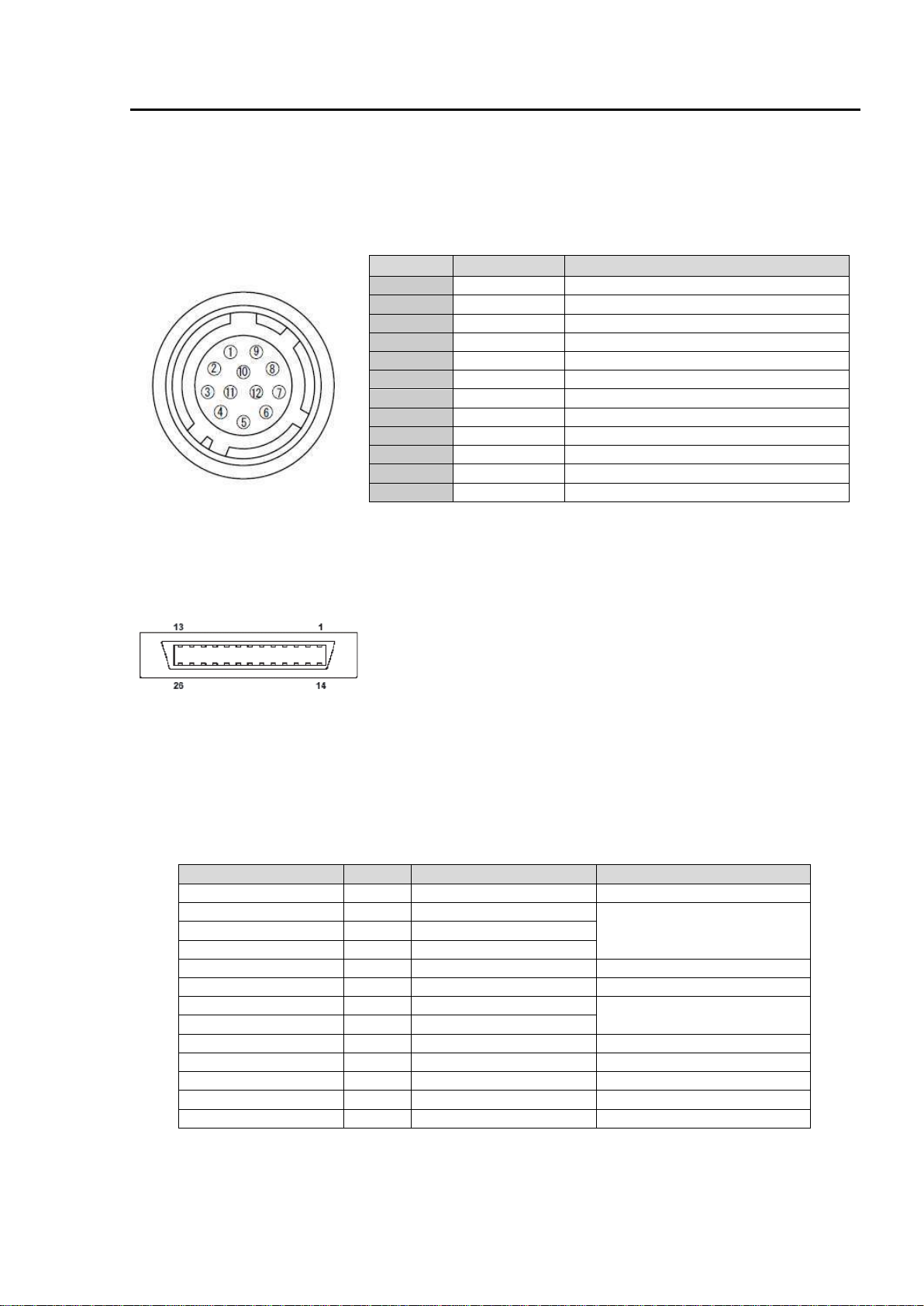
5.1.12-Pin Connector ......................................................................................6
5.2.Digital Output / Interface Connectors for Camera Link.........................................6
5.3. Input and output circuits.............................................................................7
5.3.1. Trigger input........................................................................................7
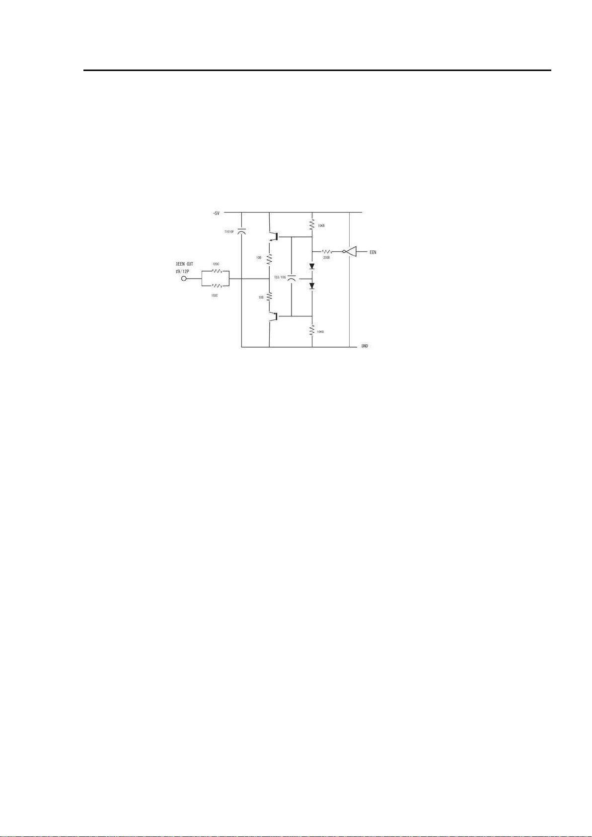
5.3.2. EEN / XEEN output (Exposure ENable)......................................................... 8
6. Functions and Operation....................................................................................9
6.1. Basic functions.........................................................................................9
6.2.Pixel Gain (flat-field) correction (PRNU correction)........................................... 10
6.3.Pixel black level correction (DSNU / FPN correction) ......................................... 10
6.4.Shading correction .................................................................................. 11
6.5. Binning ................................................................................................ 11
6.6.Operation modes .................................................................................... 12
6.6.1. No-Shutter mode with Internal line rate generator........................................ 13
6.6.2. No-Shutter mode with External Trigger...................................................... 14
6.6.3. Shutter-Select mode with Internal line rate generator.................................... 14
6.6.4. Shutter-Select mode with External trigger .................................................. 15
6.6.5. Pulse Width Control (PWC) mode.............................................................. 16
6.6.6. Auto Reset mode................................................................................. 17
6.7.Scan rate and exposure time range .............................................................. 18
6.7.1. Minimum cycle time of external trigger...................................................... 18
6.7.2. Minimum trigger pulse width................................................................... 18
6.8.Relationship between Trigger and LVAL......................................................... 18
6.9.Compatibility of trigger modes and functions .................................................. 18
6.10. Rear panel indicator ................................................................................ 19
7. Configuring the camera ................................................................................... 20
7.1.SW-2001T-CL Command list........................................................................ 20
8. Functions listed alphabetically by command acronyms............................................. 24
8.1 Command AHRS – Request status after One-Push AWB........................................ 24
8.2 Command AL – Automatic Line Rate Reference Level......................................... 24
8.3 Command AR – Automatic Line Rate setting .................................................... 24
8.4 Command ARST – Auto Reset Mode............................................................... 24
8.5 Command AW – Activate One-push Auto White Balance (AWB) - Gain...................... 24
8.6 Command AH - Activate One-push Auto White Balance (AWB) - Shutter................... 25
8.7 Command BA – Bit Allocation...................................................................... 25
8.8 Command BI – Binning (Horizontal only)......................................................... 25
8.9 Command BL – Master Black Level................................................................ 25
8.10 Commands BLR and BLR – Black level red and black level blue.............................. 26
8.11Command EI – Interlocked R, G and B exposure................................................ 26
8.12Command GA – Master Gain Level ................................................................ 26
8.13Commands GAR and GAB – Gain level red and gain level blue............................... 26
8.14 Command NK – Knee function enable/disable .................................................. 26
8.15Commands KSR, KSG and KSB – Knee slope for R, G and B.................................... 27
8.16Commands KPR, KPG and KPG – Knee point for R, G and B................................... 27
8.17 Command LR - Line Rate (Scan Rate) ............................................................ 27
8.19Command PBC – Enable pixel black (FPN) correction.......................................... 28
8.20 Command PBR – Run pixel black correction and store to user area......................... 28
8.21Command PER – Programmable exposure – Red ................................................ 28
8.22Command PEG – Programmable exposure – Green ............................................. 28
8.23Command PEB – Programmable exposure – Blue................................................ 28
8.24Command PGC – Enable Flat-field correction (Pixel gain).................................... 29
8.18 Command NOSR – Enable noise reduction........................................................ 28

SW-2001T-CL
3
8.25Command PGR – Run Flat-field correction and store in user area........................... 29
8.26Command SDC – Select shading correction mode .............................................. 29
8.27Command SDR – Run shading correction......................................................... 29
8.28Command SDS – Request status after executing shading correction command............ 31
8.29Command TG – Trigger Origin ..................................................................... 31
8.30 Command TI – Trigger input ....................................................................... 31
8.31Command TP – Trigger polarity ................................................................... 31
8.32Command TR – Trigger Mode....................................................................... 31
8.33Command TS – Test pattern ....................................................................... 32
8.34Command WB – White Balance .................................................................... 33
8.35Factory default settings............................................................................ 33
8.36Serial communication............................................................................... 34
9Camera Control Tool for SW-2001T-CL ................................................................. 36
9.1 Control Tool Windows ................................................................................. 36
9.2 Camera Control Tool Interface....................................................................... 37
9.3 Using Camera Control Tool ........................................................................... 39
10 External appearance and Dimensions................................................................... 40
11 Specifications............................................................................................... 41
11.1 Typical data ............................................................................................. 41
11.2 Spectral sensitivity ..................................................................................... 43
12 Appendix..................................................................................................... 44
12.1 Precautions .............................................................................................. 44
12.2 Typical Sensor Characteristics........................................................................ 44
12.3 References............................................................................................... 44
13 User's Record ............................................................................................... 45

SW-2001T-CL
4
1. General
SW-2001T-CL is a 3CCD line scan camera using three 2048 pixel line sensors mounted on a prism, for
the R, Gand B channels. It operates with a40 MHz pixel clock,resulting in a maximum line rate of
19 047 lines per second.
The camera outputs digital data in 3 x 8bits or 3 x10 bits format via Camera Link. The camera is
configured by software through the serial communication port ofthe Camera Link interface, orvia
RS-232C through a12-pin connector.
2. Standard composition
The standard camera composition consists of the camera body. Alens isnot included with the
delivery.
The camera is available in the following versions:
SW-2001T-CLwith F-mount (default)
SW-2001T-CLwith M52-mount (factory option)
3. Main features
•3CCD line scan camera with 2048 pixel resolution
•Dichroic RGB beam splitter prism
•19 047 lines per second scan rate(@No-Shutter mode)
•40 MHz pixel clock
•3x 8 bits or3 x 10bits output through Camera Link interface
•F-mount lens adapter. Optional M52-mount
•Flat-field correction. Two point pixel-by-pixel compensation on each RGB channel
•Shading correction
•Color Shading Compensation
•One-push white balance
•Test pattern generator( Color bar, Gray, white ) for set-upand trouble shooting
•Electronic shutter (for selected modes)
•Built-indiagnostics
•Short ASCII commands set-upvia RS232C orCamera Link
•Setup by Windows 7/8/10 software

SW-2001T-CL
5
4. Locations and functions
Fig. 1 Location of external features
1 Camera Link base connector (1) (*Note)
2 Camera Link medium connector (2) (*Note)
3 12-pin connector for DC +12, External trigger and RS-232C
4LED indicator Orange, steady: Initializing or One-push operation
Green, steady: Operating, but not receiving external trigger
Green,flashing: Operating and receiving external trigger
5One-push auto white balance button
6SW-1
7Nikon F-Mount lens adapter (M52-mount available asfactory option)
8 Mounting holes 8 x M3, depth 5mm
*Note: When a Camera Link cable is connected tothe camera, please do not excessively tighten
screws by using driver. The Camera Link receptacle on the camera might be damaged.
For security, the strength to tighten screws is less than 0.291 Newton Meter (Nm).
Tightening by hand is sufficient in order to achieve this.
12pin connector

SW-2001T-CL
6
5. Connectors
5.1. 12-Pin Connector
Type: HR10A-10R-12PB-01 Hirose (Male) or permissible substitute
Use the part number HR10A-10P-12S for the cable side
Pin No.
Signal
Remarks
1
GND
2
+12V DC in
3
GND
4
Reserved
Do not connect
5
GND
6
RxD in
RS-232C
7
TxD out
RS-232C
8
GND
9
XEEN out
10
Trigger in
TI=1, or set TI=0 for input via CL
11
+12V DC in
Option
12
GND
5.2. Digital Output / Interface Connectors for Camera Link
Type: 26P MDR Connector 3M 10226-1A10JL
Fig. 3 Camera Link connector
This camera can be used with all Camera Link products that comply with the AIA Camera Link
standard. Cables, transmission systems and frame grabbers/acquisition boards that do not comply
with the Camera Link standard may work with this camera, but JAI Camera Solutions cannot be held
responsible for loss in performance or damage of equipment, including the camera.
Connector 1 (24Bit, 30 Bit)
Pin No
In/Out
Name
Note
1,14
Shield
GND
2(-),15(+)
O
TxOUT0
Data out
3(-),16(+)
O
TxOUT1
4(-),17(+)
O
TxOUT2
5(-),18(+)
O
TxClk
Clock for CL
6(-),19(+)
O
TxOUT3
Data out
7(+),20(-)
I
SerTC (RxD)
LVDS Serial Control
8(-),21(+)
O
SerTFG (TxD)
9(-),22(+)
I
CC1 (Trigger)
Trigger
10(+),23(-)
I
CC2(Reserved)
11,24
N.C
12,25
N.C
13,26
Shield
GND
Fig. 2 12-pin connector

SW-2001T-CL
7
Connector 2 ( Used only for 3 x 10 Bit output)
Pin No
In/Out
Name
Note
1,14
Shield
GND
2(-),15(+)
O
TxOUT0
Data out3(-),16(+)
O
TxOUT1
4(-),17(+)
O
TxOUT2
5(-),18(+)
O
TxClk
Clock for CL
6(-),19(+)
O
TxOUT3
Data out
7(+),20(-)
N.C
8(-),21(+)
N.C
9(-),22(+)
N.C
-10( ),23(+)
N.C
11(-),24(+)
N.C
12(-),25(+)
N.C
13,26
Shield
GND
The SW-2001T-CL follows the Camera Link standard in all respects.
Please refer to the Camera Link version 1.1 specifications for detailed information on bit
assignments of 24-bit RGB and 30-bit bit output.
5.3. Input and output circuits
5.3.1. Trigger input
The External Trigger signal can be applied either through the Camera Link connector or at pin 10 of
the 12-pin connector. The command to change this setting is TI (Trigger Input). TI=0 for Camera
Link connector (factory default) and TI=1 for 12-pin connector. The input via the 12-pin connector is
AC coupled.
To allow long pulses, which may be required when using the Pulse Width Control (PWC) trigger
mode, the input circuit is designed as a flip-flop circuit. The leading and trailing edges of the trigger
pulse activate the circuit.
The trigger input polarity can be changed by the command TP. At the 12-pin connector the External
Trigger input is 4V ± 2V (TTL). It can be changed to 75 ohm termination by an internal switch setting
(SW 801-2).
Fig. 4 Trigger input (12-pin)

SW-2001T-CL
8
5.3.2. EEN / XEEN output (Exposure Enable)
This output corresponds to the exposure (accumulation) time of the camera. It works together with
all operation modes. It is, however, not active when the test pattern function is enabled.
The EEN signal is available at the Camera Link connector and at the 12-pin connector at the same
time.
At the Camera Link connector this signal has positive logic.
At pin 9 of the 12-pin connector the signal has negative logic, and is therefore named XEEN. The
output circuit is a 75 ohm complementary emitter follower. The circuit is powered from the 5V
supply, resulting in an output level of more than 4V. It is not terminated.
Fig. 5 XEEN Circuit (12-pin)

SW-2001T-CL
8
6. Functions and Operation
6.1. Basic functions
The SW-2001T-CL is built around three high-performance CCD line scan image sensors mounted on a
prism block, as illustrated in Figure 6.
During exposure, the incoming light is converted to electrons (electric charge) in the photodiodes
(active pixels). The transfer gate controls the transfer of charge from photodiodes to the shift
register. Activating the transfer gate terminates the exposure cycle, transfers the charge to the
Horizontal Shift Register (2-phase buried channel CCD shift register) and starts a new exposure
cycle. The line is subsequently read out in a single sequence starting with pixel 1.
The exposure time is normally the same as the cycle time (in No-Shutter mode). By using the
Exposure Control Gate (in Shutter-Select or Pulsed Width Control trigger modes) the exposure time
can be individually set to be shorter than the cycle time (the inverse of line rate). This also allows a
fixed exposure time, independent of the line rate. In the SW-2001T-CL the exposure time can be set
individually for all three channels.
Fig. 6 Principle of a 3CCD line scan camera
Red channel CCD sensor
Green channel CCD sensor
Blue channel CCD sensor
Y-axis
Motion of object
X-axis
Sensor scanning
IR-cut filter

SW-2001T-CL
10
6.2. Pixel Gain (flat-field) correction (PRNU correction)
Pixel Response Non-Uniformity is, as the name expresses, a non-uniformity of the response of each
individual pixel. This means that for a fixed light level each pixel will have a slightly different
output level (response).
To correct for PRNU, the camera’s internal correction circuit captures one or several lines of data
under non-saturated illuminated conditions (not more than 80% of maximum - recommend level is
half of maximum), and the average across the line is calculated. Based on this average, coefficients
are then generated for each individual pixel. The coefficient has the function of multiplying the
pixel output with factor greater or less than 1. These coefficients are stored in a non-volatile
memory, and are therefore maintained after power down.
6.3. Pixel black level correction (DSNU / FPN correction)
Dark Signal Non-Uniformity or Fixed Pattern Noise is, as the name expresses, fixed pattern on the
sensor output, which is not dependant on the incoming light.
To correct for DSNU/FPN, the camera-internal correction circuit captures one or several lines of
data under dark conditions (the lens must be covered by a lens cap), and the average across the line
is calculated. Based on the average, coefficients are then generated for each individual pixel. The
coefficient has the function of adding or subtracting a value to the pixel output. These coefficients
are stored in a non-volatile memory, and are therefore maintained after power down.
As the dark signal is highly dependant on the exposure time, this correction must be performed
Max
Min
Multiply by
Factor > 1
Multiply by
Factor < 1
Before correction: Non-uniform response from pixel to pixel
Average
After correction: flat response from pixel to pixel
Average
Max
Before correction: dark signal non-uniformity from pixel to pixel
Subtract factor
Add factor
Min
Average

SW-2001T-CL
11
under the operating conditions (exposure time and line rate) that will be used by the application.
6.4. Shading correction
Shading is caused either by illumination with uneven distribution of light across the surface, or by
vignetting towards the edges of a lens.
The shading correction incorporated in the camera will compensate for this effect by as much as
20% of the brightest signal.
Shading is not compensated for each individual pixel. The signal is averaged across group of 8 pixels
in relation to the whole line. The pixel response non-uniformity will be superimposed on the output
also after shading correction has been performed. Therefore, it is recommended to perform a pixel
gain (flat-field) correction after shading correction.
The Pixel Gain (flat-field) correction function will also be used to compensate for shading, but it
cannot handle a very wide dynamic range.
The shading correction can be configured to compensate each channel separately or tracking the
green channel.
6.5. Binning
The binning function in this camera combines the charge collected in two adjacent pixels. This
halves the effective resolution to 1024 pixels, but doubles the sensitivity. The line rate is not
affected by binning.
Average
After correction: Flat dark signal response from pixel to pixel
Shading caused by uneven illumination or vignetting at the edges of the lens.
Pixel response non-uniformity will be superimposed on the output signal
Individual shading correction
per channel
Shading correction tracking
the green channel

SW-2001T-CL
12
6.6. Operation modes
The SW-2001T-CL provides three basic modes of operation: No-shutter, Shutter-Select and Pulse
Width Control (PWC). The Shutter-Select and PWC modes also allow the user to set the exposure
time independently from the scan rate, by making use of the electronic shutter (the Exposure
Control Gate of the CCD sensor).
The following sections describe these modes. The detailed timing of the video output, shown in
figure 8, is common to all modes.
1line 2100 (2150)
1CLK=25ns

SW-2001T-CL
13
6.6.1. No-Shutter mode with Internal line rate generator
In this mode the camera does not accept an external trigger signal, as the line rate is generated
from an internal clock (user programmable, command LR). The exposure time is directly
proportional to the line rate (Texp = 1/line rate). This mode is used when there is no external trigger
signal available, and the speed of the object is fixed or can be pre-determined.
The line rate can be varied from 1 line period (L) to 1024L in 1 clock (25ns) steps. 19 kHz down to 18
Hz. When using this mode, a special function called “One-push Auto Line rate” is available. This
mode automatically maintains a constant output level by changing the line rate. See chapter 7
(configuring the camera) for further details on this function. The line rate is automatically adjusted
in order maintain sensitivity without reducing the S/N ratio.
To use this mode:
Set function Trigger mode, No-Shutter TR=0
Trigger origin, internal TG=0
Line rate LR=2100 to 2150400
(52.5 µs to 53.8 ms in 25ns increments)
Optional functions when using this mode:
One-push auto line rate AR=0
Auto line rate reference AL=0 to 1023
One-Push white balance WB
Fig. 9 No-Shutter mode with Internal line rate generator
Important Note
•The “one-push auto line rate” function is not recommended for continuous web applications, as
the speed of motion needs to be adjustable in order to maintain the aspect ratio of the image.
•Only gain based One-Push white balance functions (WB) is available with this mode.

SW-2001T-CL
14
6.6.2. No-Shutter mode with External Trigger
In this mode, the exposure time is directly proportional to the line rate. The line rate is
generated externally by a trigger signal. This mode isused when an external trigger signal is
available, e.g. from an encoder, and the scan rate can becontrolled bythis signal. The camera
can accept anexternal trigger through the Camera Link connector orthough the 12-pin connector.
To use this mode:
Set function Trigger mode, No-Shutter TR=0
Trigger origin, external TG=1
Trigger input TI=0 or 1
Important note:
•When the one-push white balance has been initiated and the rear panel LED shows orange, the
camera must receive continuous external trigger pulses corresponding to the frequency and duty
cycle used in the application.
Fig. 10No-Shutter mode with External Trigger
6.6.3. Shutter-Select mode with Internal line rate generator
This mode allows the user to have full control of the line rate and the exposure time individually, by
programming separate timing generators. Subsequently the camera does not accept an external
trigger signal in this mode.
To use this mode:
Set function Trigger mode, Shutter-Select TR=1
Line rate LR=53.75μs to 53.76ms
Trigger origin, internal TG=0
Individual R, G and B exposure EI=0(individual)

SW-2001T-CL
15
EI=1(tracking with G)
Programmable exposure PER/PEG/PEB=80 to 2150400 (in 25ns steps)
Important note:
•If using individual exposure, the EEN signal represents the channel with the longest exposure time
Fig. 11 Shutter-Select mode with Internal line rate generator (and individual exposure)
6.6.4. Shutter-Select mode with External trigger
This mode allows the user to have full control of the exposure time, by programming a timing
generator, while the line rate is controlled by an external trigger signal. The camera can accept an
external trigger through the Camera Link connector or though the 12-pin connector.
To use this mode:
Set function Trigger TR=1
Trigger origin, external TG=1
Individual R, G and B exposure EI=0(individual)
EI=1(tracking with G)
Programmable exposure PER/PEG/PEB=80 to 2150400 (in 25ns steps)

SW-2001T-CL
16
Important note:
•If using individual exposure, the EEN signal represents the channel with the longest exposure time
Fig. 12 Shutter-Select mode with External trigger (and individual exposure)
6.6.5. Pulse Width Control (PWC) mode
In this mode, the user has full control of both the line rate and the exposure time of each line via
the External Trigger input.
At the falling edge of the External Trigger signal, the exposure is initiated, and at the rising edge
the exposure is terminated and read out. The camera can accept an external trigger through the
Camera Link connector or though the 12-pin connector.
To use this mode:
Set function Trigger mode, PWC TR=2
Important Note:
•Possible pulse width:
1.2μsec. to 2 sec. (there is no upper limit for the pulse width, but to avoid image deterioration it
is recommended not to exceed 2 seconds.
•One-push white balance by gain setting only.
•When the one-push white balance has been initiated and the rear panel LED shows orange, the
camera must receive continuous external trigger pulses corresponding to the frequency and duty

SW-2001T-CL
17
cycle used in the application.
Fig. 13 Pulse Width Control mode
6.6.6. Auto Reset mode
In this mode, when the interval of the trigger pulse is more than 55ms, the SW-2001T-CL
automatically returns to continuous operation with the line rate of 52.5μs . At this time, DVAL and
Video OUTPUT are disable in order to prohibit charge due to dark current to add up in the sensor in
standby periods.
While the Auto Reset mode is “ON”, if the trigger interval becomes less 55ms, SW-2001T-CL
operates in the ordinal trigger mode selected.
Note: SW-2001T-CL functions properly according the selected operation mode while the Auto
Rest mode is “ON”. However, if the system uses LVAL, it is recommended to set the Auto
Reset at “OFF” as LVAL is always output.
For this mode, SW-2001T-CL provides Auto Reset mode command “ARST”.
In the default setting, “ARST” is set at “ 0 “ (OFF). In order to activate this mode, “ARST” should
be set at “1”.
The following is the concept of the Auto Reset Mode.

SW-2001T-CL
18
Trigger
LVAL
Exposure
EEN
DVAL
> 55ms < 53.7ms <53.7ms
<55ms:
Normal Trigger
operation
>55ms: Auto reset operation
DVAL & Video Out disable Normal Trigger operation
Auto Reset Mode
6.7. Scan rate and exposure time range
6.7.1. Minimum cycle time of external trigger
Mode
Minimum trigger cycle
No-Shutter
C1 + 52.5μs
Shutter-Select
C1 + 53.7μs
PWC
Exposure time 2us ~52.33us
C2
Exposure time 52.33us ~
C2 + (Exposure Time – 52.33us)
C1 =0.1μs; C2= 54.2μs
6.7.2. Minimum trigger pulse width.
Mode
Minimum trigger pulse width
No-Shutter
500ns
Shutter-Select
500ns
PWC
1.2µs
6.8. Relationship between Trigger and LVAL
Mode Trigger
Trigger and LVAL mode
Relations
No-Shutter
Internal
External
Synchronous
Shutter-Select
Internal
External
Synchronous
Asynchronous
PWC
External Asynchronous
6.9. Compatibility of trigger modes and functions
Mode
Functions
Trigger
Binning
Pixel gain
& black
correction
Shading
correction
One-Push WB
Gain &
black
level ctr.
Program
line rate
Program
exposure
time
Gain
Shutter
No-Shutter
Internal
Yes
Yes
Yes
Yes
No
Yes
Yes
No
External
Yes
Yes
Yes
Yes
No
Yes
No
No
Table of contents
Other JAI Security Camera manuals