jali Dresser-Multi User manual

Page 1 of 11Assembly Instructions: Multi Section Dresser
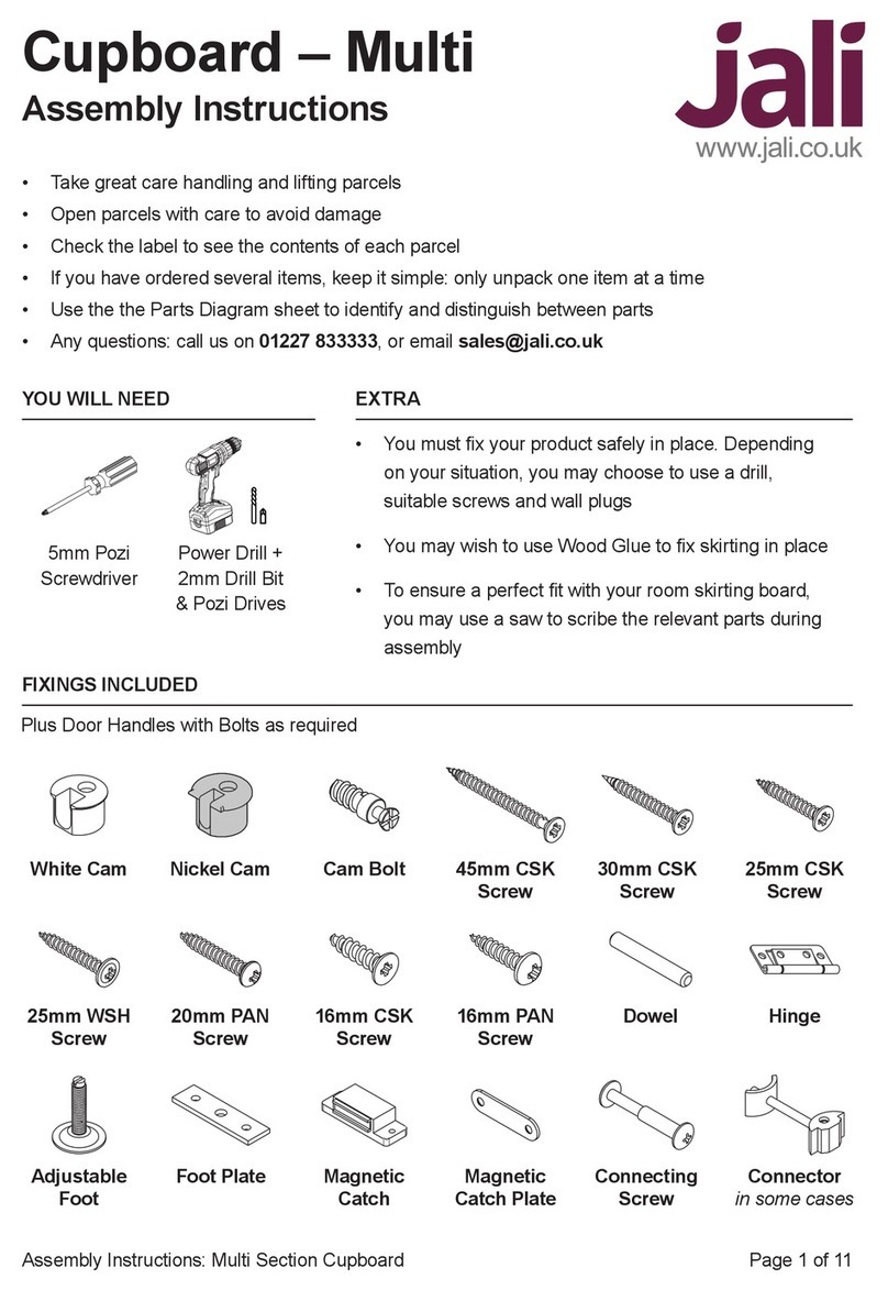
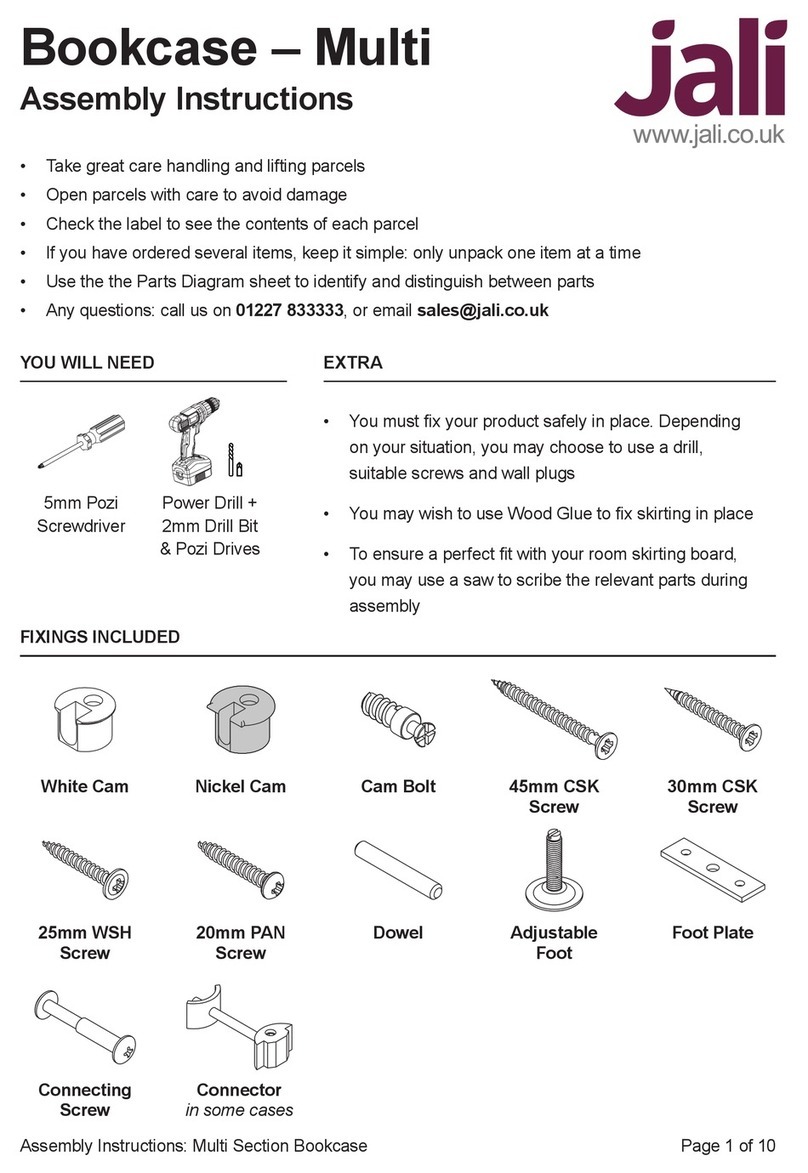
5mm Pozi
Screwdriver
Power Drill +
2mm Drill Bit
& Pozi Drive
Dresser – Multi
Assembly Instructions
YOU WILL NEED EXTRA
• Take great care handling and lifting parcels
• Open parcels with care to avoid damage
• Check the label to see the contents of each parcel
• If you have ordered several items, keep it simple: only unpack one item at a time
• Use the the Parts Diagram sheet to identify and distinguish between parts
• Any questions: call us on 01227 833333, or email sales@jali.co.uk
• You must x your product safely in place. Depending
on your situation, you may choose to use a drill,
suitable screws and wall plugs
• You may wish to use Wood Glue to x skirting in place
• To ensure a perfect t with your room skirting board,
you may use a saw to scribe the relevant parts during
assembly
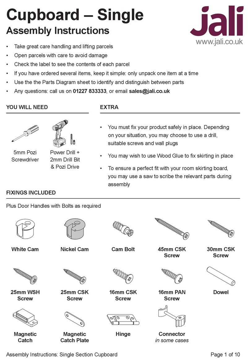
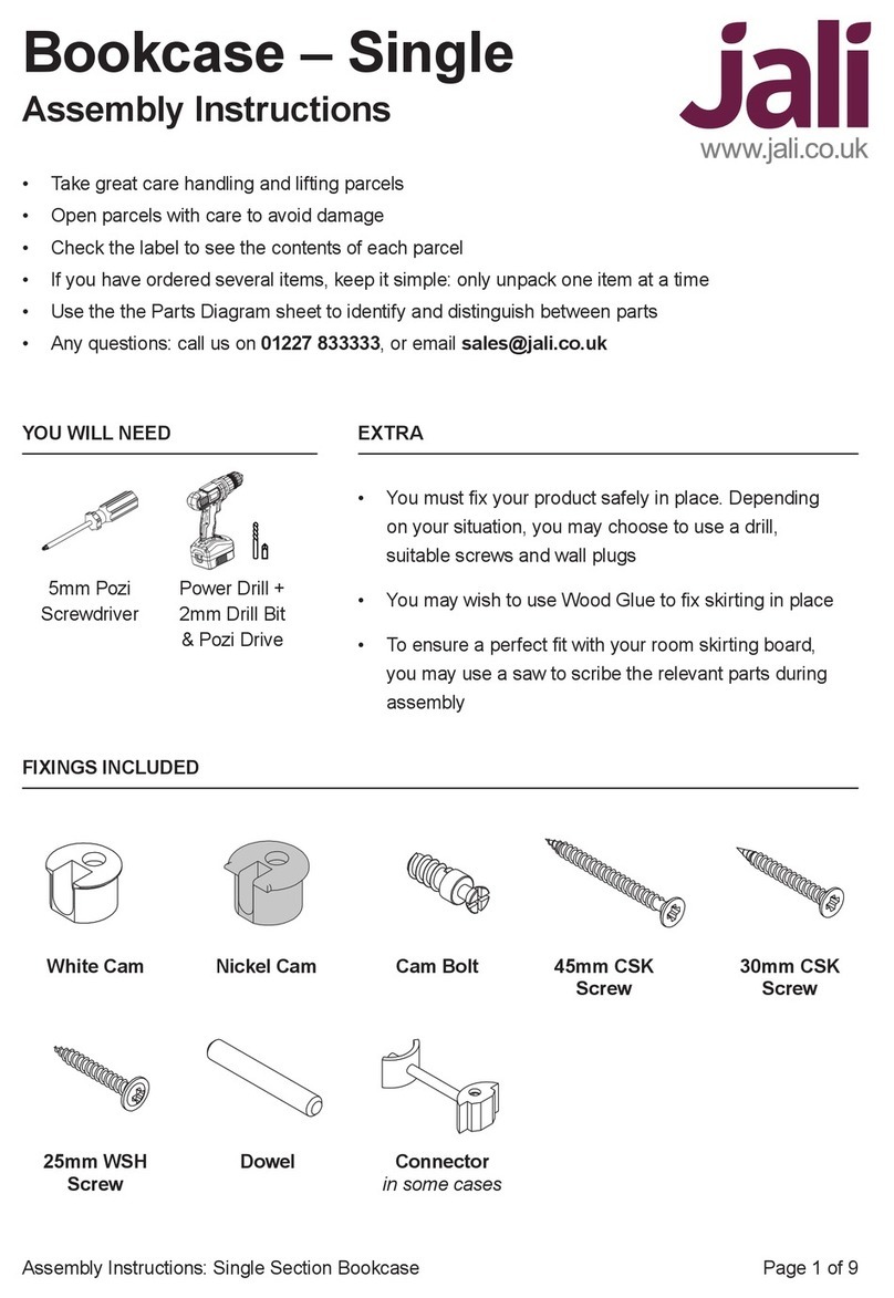
FIXINGS INCLUDED
White Cam Nickel Cam Cam Bolt
25mm WSH
Screw
Adjustable
Foot
45mm CSK
Screw
30mm CSK
Screw
16mm PAN
Screw
Dowel
Connector
in some cases
20mm PAN
Screw
Magnetic
Catch
Foot Plate
16mm CSK
Screw
Magnetic
Catch Plate
25mm CSK
Screw
Hinge
Plus Door Handles with Bolts as required

Page 2 of 11Assembly Instructions: Multi Section Dresser
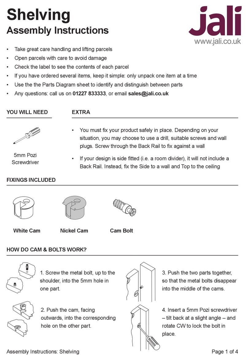
1. Screw in the Cam Bolt, up to
the shoulder, into the 5mm hole
in one part.
2. Push the Cam, facing
outwards, into the corresponding
hole on the other part.
3. Push the two parts together,
so that the Cam Bolts disappear
into the middle of the Cams.
4. Insert a 5mm Pozi screwdriver
– tilt back at a slight angle – and
rotate CW to lock the Cam.
HOW DO CAM & BOLTS WORK?
There is a lower (cupboard) section and an upper (shelving) section. Both sections are made up by
assembling individual boxes which connect together. Your design may be dierent to this example,
but don’t worry; it will become clearer as we work through.
SEE HOW IT COMES TOGETHER
Top Mid Upright
Box Top
Inner Side
Outer Side
LH Upright
Box Back
Box Top
LOWER
UPPER
LH Skirt
LH Side
LH Upright
RH Upright
Outer Side
Shelf
Front Skirt
Box Base
Door
Box 1
Box 4
Box 2
Box 5
Box 3
Box 6
Countertop

Page 3 of 11Assembly Instructions: Multi Section Dresser
PLACE FIXINGS
We’ll start with the lower section. You can
use the following instructions to prepare the
upper section too (with minor adaptations), but to
keep things simple, come back to this later.
1. Place Nickel Cams in the Outer Sides, as they
will be visible. Ensure they are facing outwards.
Using a screwdriver, or power tool on a low
setting, screw the Cam Bolts into the
available 5mm holes.
Here’s just the example lower section in more detail. Each box is made up of a Box Top, Box Base,
Box Back, LH Side, RH Side and Valance. Look out for engravings to help identify parts. Depending
on your design, boxes may feature Shelves, Dividers and/or Doors. Refer to the Parts Diagram to
conrm this arrangement.
The Outer Sides go at each end of the whole unit, e.g. Box 1 LH Side & Box 3 RH Side.
The rest are Inner Sides. Inner Sides will have Adjustable Feet. Inner RH Sides have a spacer
attached where the boxes will be connected together.
Shown without Doors
Box 1
Box 2
Box 3
Valance
Cam BoltNickel Cam
Box 1 LH Side
Adj. Foot
Box 3 RH Side
Outer Side

Page 4 of 11Assembly Instructions: Multi Section Dresser
2. For all the remaining Box Sides use White Cams instead, as they will be hidden. Place the White
Cams in all the available holes, facing outwards. Attach the Adjustable Feet using the Foot Plate and
20mm PAN Screws for each assembly. However, you should pilot drill these rst to avoid splitting
the wood. The Adjustable Foot should be set to about 25mm.
20mm PAN Screw
Foot Plate
Adjustable Foot
Set to 25mm 25mm
White Cam Inner Side
Fit a Cam Bolt into each
hole on the top side
Fit a second Cam Bolt
into the same holes on
the underside
Divider
3. This example does not include
any Dividers. However, if your
design does, look for 5mm ‘through’
holes. Each hole requires a Cam Bolt
on each side. Screw in all Cam Bolts
required on one side of the Divider, then
turn the Divider over, and screw in Cam
Bolts, in the same holes, on the opposite side.
4. On taller units, one or more of the outer
Shelves (in the outer boxes) may have a cam
hole. Place Nickel Cams in these.
5. For all the Uprights, t Cam Bolts to all 5mm holes.
There is also a 6mm hole – leave this for now.
Shelf
Normal
Shelf
with Cam/s
RH Upright
Mid Upright/s
LH Upright
Cam Bolt

Page 5 of 11Assembly Instructions: Multi Section Dresser
6. Place White Cams in the Box Base, Box Top and Valance cam holes. Depending on your design,
the Valance strip could be taller than this example. Screw Cam Bolts into the 5mm holes along the
Box Base front edge. Leave the 6mm Box Top holes for now.
White Cam
Cam Bolt
Valance
Box Base
Front Edge
Box Top
Front Edge
White Cam
The following instructions will cover the assembly process for a single box. Repeat this process for
each box in your design. Refer to the Parts Diagram to conrm the conguration of each box. Note
that the following example doesn’t contain Dividers.
7. With the front edges toward the oor, t the Box Top to the RH
Side and secure with 45mm CSK Screws. Then proceed to add all
the Shelves. Wherever (if) the Box Sides feature central
Cam Bolts, place one of the Shelves with cams,
with the cam facing towards the Box Base.
BOX ASSE M BLY
If the box has more than one Divider, start by placing all the necessary shelves between the
Dividers. Wherever (if) the Divider features a central Cam Bolt, place one of the Shelves
with cams. After locating the other normal Shelves, lock these Shelf cams
into place to hold the structure together.
Note about Dividers
If the box has just one Divider, the Box Top and Box Base can now be
attached either end of the Divider, before xing with 45mm CSK Screws.
Pilot drill, then x with
45mm CSK Screws
RH Side
Cams to the oor
Box Top
Dowel holes to
the oor, engraved
label facing towards
Short tenons
for Outer Sides
Long tenon

Page 6 of 11Assembly Instructions: Multi Section Dresser
8. Once the Shelves and the Box Base are
placed in the RH Side, the LH Side can be
located. Ensure that the Shelves with cams
align with the Cam Bolts in the LH Side,
and lock these into place. See Page 2 for
help with cams. Lock the cams in the Box
Top and Box Base.
9. Align the Valance White Cams with the
Box Base Cam Bolts, then lock each cam
securely in place.
Fit 45mm CSK Screws through the 4mm holes
(in the RH Side) into the Box Top, Box Base and
Shelves with cams
LH Side
Valance
10. Place the Box Back onto the assembly
with the engraving upwards and towards
the Box Top as shown. Slide the
Box Back over until the top
edge aligns perfectly with the
Box Top. Fix this top edge with
the 25mm WSH Screws. Then
x down one side, accurately
realigning the edge to the
Side as you go. This should force
the box square. Once all sides are xed
in place, continue to screw through the remaining 3mm
holes with 25mm WSH Screws to help secure the Shelves.
Fix with 25mm
WSH Screws
Box Back
NOW ASSEMBLE THE OTHER LOWER SECTION BOXES

Page 7 of 11Assembly Instructions: Multi Section Dresser
12. Fit the Uprights to the Sides by aligning
the cams and locking them into place.
Ensure all the cams
are fully open before
placing the Uprights.
To lock the Mid Upright cams, use a
pozi screwdriver via the access holes
on the Inner Box Sides
Fix with
Connecting Screws
Fix with
Connecting Screws
LH Upright
Mid Upright
RH Upright
11. Carefully stand the boxes up and position them
adjacent to each other in the correct order.
If they are too large to do safely, you’ll
need to enlist some help. Adjust
the feet height as necessary
to bring the boxes in
line with each other.

Page 8 of 11Assembly Instructions: Multi Section Dresser
13. Locate the Countertop to the Box Tops using Dowels. It can be glued into place, screwed into
place with 45mm CSK Screws from beneath, or left as is. For exceptionally wide units the Countertop
and Skirting may be supplied in several lengths.
Fit Cam Bolts into the 5mm holes on the Countertop.
Depending on your design, you may have LH and/or RH Skirts. If you wish, you can scribe these Skirts
to match your room skirting. When placing the LH & RH Skirts, ensure that the mitre matches neatly
with the Front Skirt. They can be either glued in place, or screwed from the inside using 30mm CSK
Screws.
14. Skirting may be tted
now, or you may prefer to do this step last. Fit Dowels
into the Front Skirt holes, and push home the Front Skirt into the holes
on the Uprights and Valances. This can be glued into place, or left as is.
15. Fit Magnetic Catches beneath Box
Tops with 16mm PAN Screws.
16. Fix Handles to the Doors using the
Bolts provided.
17. Fit Magnetic Catch Plates with 16mm
CSK Screws.
18. Fix Doors in place with Hinges and
25mm CSK Screws. Ensure the butt of
the hinge clears the edge of the door, so
the doors are positioned correctly.
DOORS
15.
16.
17.
18.
Cam Bolt

Page 9 of 11Assembly Instructions: Multi Section Dresser
The upper section box
assembly follows the
same principles as the
lower section, however
these boxes do not
feature Bases or Valances.
19. Assemble each remaining
box in turn, referring back to
the previous steps.
The Back must be ush with the
bottom of the two Sides to ensure
that it sits neatly on the Countertop.
When tting the Box Back to the
box, start by aligning and xing
the bottom edge to ensure it
does not overextend.
THE UPPER SECTION
LH Side
Shelf
RH Side
Lower Section
Box Top
Box Back
Bottom Edge

Page 10 of 11Assembly Instructions: Multi Section Dresser
20. The upper section boxes t
onto the Countertop by aligning
and locking the Box Side cams
with the Countertop Cam Bolts.
21. Once all boxes are locked
in place, the Uprights can be
attached as before.
As with all Jali products, you
must take responsibility for
the safety of your furniture.
Any tall unit presents a hazard,
especially in the presence of
children and pets. Attach the
upper section to the wall by
whatever means necessary to
mitigate any risk.
FINAL ASSEMBLY
22. Depending on your design, you may have one of a variety of dierent Top styles. The most
common is simply a solid Top board, or ‘Full Top’. Locate the Top to the upper section Box Tops using
Dowels. It can be glued into place, screwed into place from beneath with 45mm CSK Screws, or left
as is. For exceptionally wide units, the Top and Skirting may be supplied in several lengths.
Full Top
Top Lip SetTop Lip
Fix with
Connector
Alternatively, you may have a Top ‘lip’. Attach this in the same way. This may be supplied as one
single component or several parts which join together with a Connector (using the hex key provided)
once in place.

Page 11 of 11Assembly Instructions: Multi Section Dresser
#jali #dresser #makeityours
AND YOU’RE DONE!
Table of contents
Other jali Indoor Furnishing manuals
Popular Indoor Furnishing manuals by other brands

Regency
Regency LWMS3015 Assembly instructions

Furniture of America
Furniture of America CM7751C Assembly instructions

Safavieh Furniture
Safavieh Furniture Estella CNS5731 manual

PLACES OF STYLE
PLACES OF STYLE Ovalfuss Assembly instruction

Trasman
Trasman 1138 Bo1 Assembly manual

Costway
Costway JV10856 manual