jali Dresser User manual

Page 1 of 9Assembly Instructions: Dresser
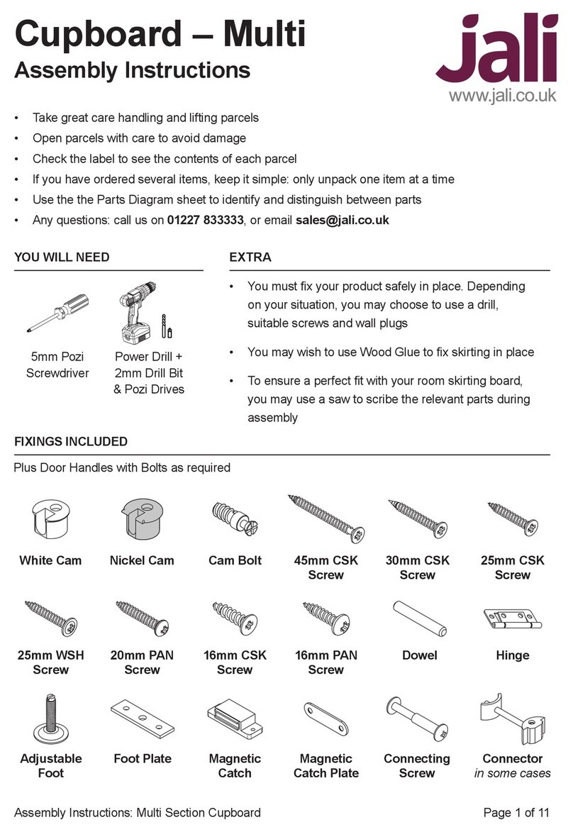
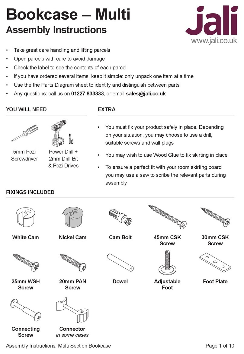
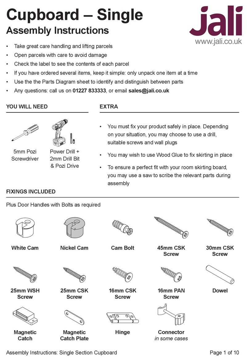
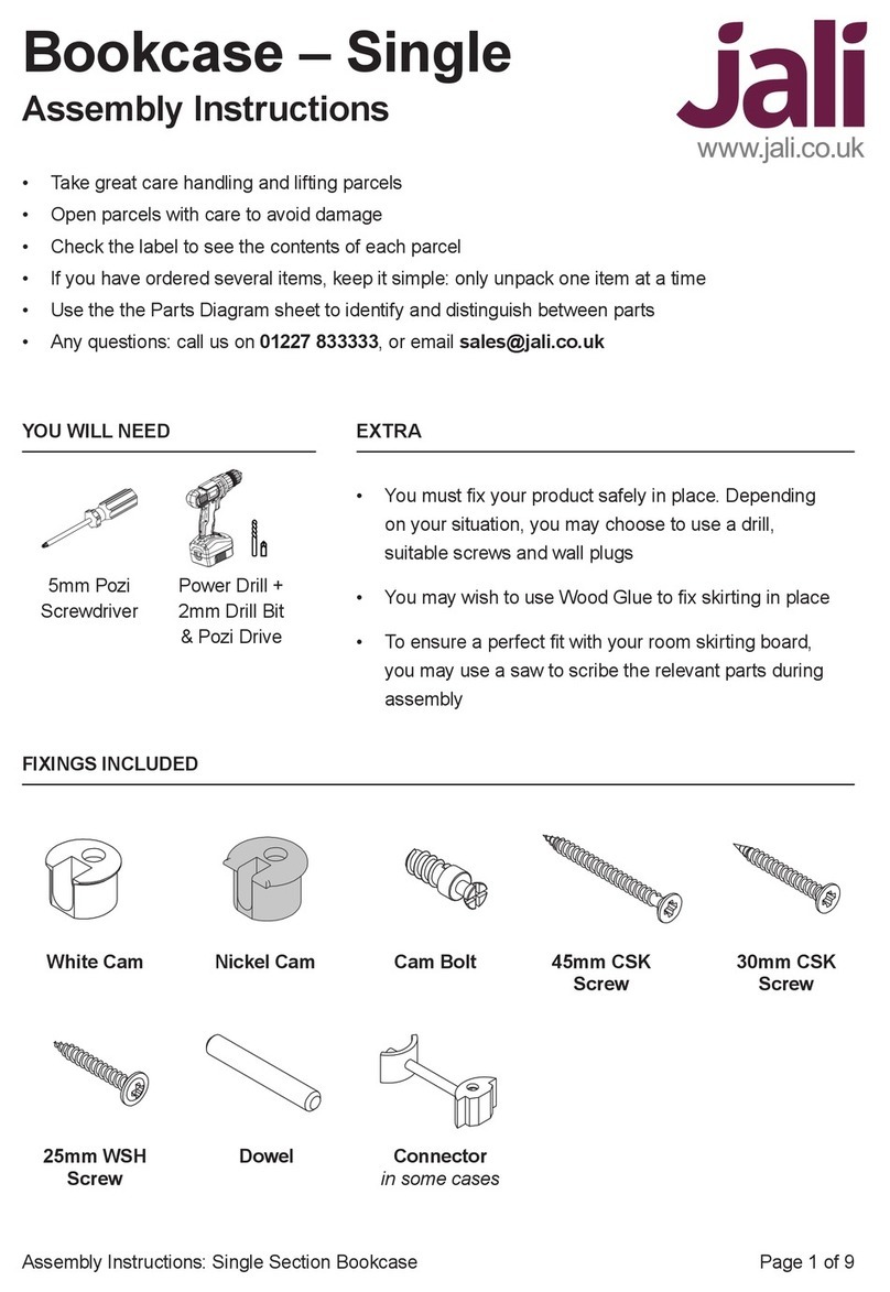
5mm Pozi
Screwdriver
Power Drill +
2mm Drill Bit
& Pozi Drive
Dresser
Assembly Instructions
YOU WILL NEED EXTRA
• Take great care handling and lifting parcels
• Open parcels with care to avoid damage
• Check the label to see the contents of each parcel
• If you have ordered several items, keep it simple: only unpack one item at a time
• Use the the Parts Diagram sheet to identify and distinguish between parts
• Any questions: call us on 01227 833333, or email sales@jali.co.uk
• You must x your product safely in place. Depending
on your situation, you may choose to use a drill,
suitable screws and wall plugs
• You may wish to use Wood Glue to x skirting in place
• To ensure a perfect t with your room skirting board,
you may use a saw to scribe the relevant parts during
assembly
FIXINGS INCLUDED
White Cam Nickel Cam Cam Bolt
25mm WSH
Screw
Adjustable
Foot
45mm CSK
Screw
30mm CSK
Screw
16mm RND
Screw
Dowel
Connector
in some cases
20mm RND
Screw
Magnetic
Catch
Foot Plate
16mm CSK
Screw
Magnetic
Catch Plate
25mm CSK
Screw
Hinge
Plus Door Handles with Bolts as required

Page 2 of 9Assembly Instructions: Dresser
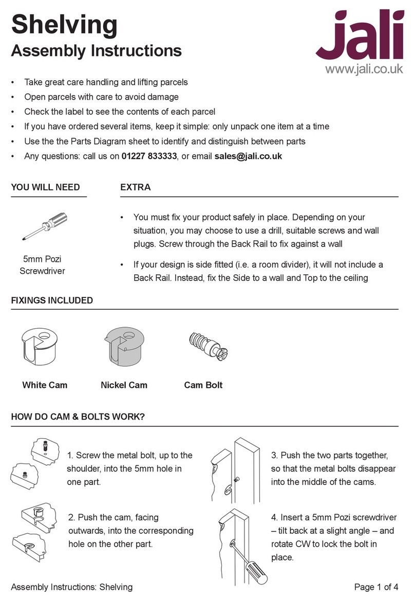
1. Screw in the Cam Bolt, up to
the shoulder, into the 5mm hole
in one part.
2. Push the Cam, facing
outwards, into the corresponding
hole on the other part.
3. Push the two parts together,
so that the Cam Bolts disappear
into the middle of the Cams.
4. Insert a 5mm Pozi screwdriver
– tilt back at a slight angle – and
rotate CW to lock the Cam.
HOW DO CAM & BOLTS WORK?
1. Start by identifying the parts. Your design may be dierent to this example, but don’t worry; it
will become clearer as we work through. There is an upper (shelving) and lower (cupboard) part.
Depending on your design, there may be Shelving inside the cupboard, as well as Base Shelf
Supports below.
SEE HOW IT COMES TOGETHER
Top
Mid Side
Upper
LH Side
Upper
LH Side
Lower
LH Skirt
LH Upright
Lower
Back
Countertop
RH Upright
Lower
RH Upright
Upper
Shelf
Front Skirt
Door

Page 3 of 9Assembly Instructions: Dresser
Base Shelf
LH Side
+ Upright
LOWER ASSEMBLY
3. Place White Cams in the Base Shelf, and on the opposite side, screw Cam Bolts into any 5mm
holes.
Take the assembled Sides & Dividers, and place them on the oor with the Upright facing down. Use
something to space them o the oor by about 2cm – if your unit has skirtings, these will be ideal.
This makes tting the Countertop much easier later, but it’s not absolutely essential.
Now we can t the Base Shelf to the LH Side. The Cam Bolts in the Base Shelf should face the
bottom of the Side, so they’ll be hidden when the unit is standing upright.
2. We’ll start with the left hand (LH) and right hand (RH) Sides, as well as any Dividers. Place Nickel
Cams into all available holes, facing outwards. Ensure Cam Bolts are tted towards the bottom of the
LH & RH Sides.
Then, nd the Uprights. Using the screwdriver, or a power tool on a low setting, screw the Cam Bolts
into the available 5mm holes. Unlike the 6mm holes, these 5mm holes do not go all the way through.
Align the LH Upright to the LH Side then lock each cam securely in place. Now do the same for the
RH Side and any Dividers.
RH Side
+ Upright
Divider
+ Upright
LH Side
+ Upright

Page 4 of 9Assembly Instructions: Dresser
5. If you have any Dividers, t these in place with the Nickel Cams and Cam Bolts on the Base Shelf.
Continue to t the shelves on the other side of the Divider. If your design has more sections, you will
have more Dividers (and Shelves). Keep going until you’ve done all the sections.
6. Fit the RH Side to the other end of the Base Shelf. Don’t forget to space it o the oor!
4. Fit any Shelves in place. Make sure that the edge of the Shelves
are ush with the inside of the lip along the top edge of the LH Side.
RH Side
+ Upright

Page 5 of 9Assembly Instructions: Dresser
7. Screw Cam Bolts into the underside of the Countertop, however, note that the Countertop may
have other holes; refer to the positions of Nickel Cams at the top of Sides & Dividers to nd out which
holes to place Cam Bolts. Locate the Countertop with these Nickel Cams and lock them into place.
If you used the skirtings to space the Uprights o the oor, the front edge of the Countertop should be
just resting on the oor, and this will make the Cam Bolts line up with the Sides & Dividers easily.
8. Beneath any Dividers, Base Shelf Supports must be attached. Fit Cam Bolts in the required 5mm
holes on the underside of the Base Shelf. Place White Cams in the Base Shelf Supports. You may
need to slacken the Uprights the Divider in order to lock the Base Shelf Support into place with the
Cam Bolts.
Attach the Adjustable Feet to the Base Shelf Support using the Foot Plate and 20mm RND Screws
for each assembly. However, you should pilot drill these rst to avoid splitting the wood.
The Adjustable Foot should be set to about 25mm.
Countertop
Base Shelf Support
Note that we are now viewing
from the opposite side
20mm RND Screw
Foot Plate
Adjustable Foot
Set to 25mm 25mm

Page 6 of 9Assembly Instructions: Dresser
9. Most units are supplied with one Back panel which ts across the whole width of the unit, but if
your unit is particularly big it will come in two or more sections.
Fit the Back between the grooves in the LH/RH Sides, and the groove in the Countertop. It should be
level with the bottom of the Base Shelf, and the holes near the bottom edge should be about 9mm
above the bottom. The holes along the top will be much closer to the edge. Ensure that that any holes
across the middle of the Back line up with the shelves. Screw the Back in place using the 25mm
WSH Screws, starting down one edge and aligning as you go to keep the unit square.
Carefully lift the unit into the upright position.
10. Fix Handles to the Doors using
the Bolts provided.
11. Fix Doors in place with Hinges
and 25mm CSK Screws. This will be
easier with a helping hand! Ensure
the butt of the hinge clears the
edge of the door, so the doors are
positioned correctly.
Fix with 25mm CSK Screws

Page 7 of 9Assembly Instructions: Dresser
13. Fit Dowels into the Front Skirt holes, and push home the Front Skirt into the holes on the Uprights.
This can be glued into place, or left as is. Depending on your design, you may have LH and/or RH
Skirts. If you wish, you can scribe these Skirts to match your room skirting. When placing the LH
& RH Skirts, ensure that the mitre matches neatly with the Front Skirt. They can be either glued in
place, or screwed from the inside using 30mm CSK Screws.
Now the lower section is complete, you can move it into its nal position.
Fix with 16mm
CSK Screws
Fix with 16mm
RND Screws
12. Fix Magnetic Catches to the underside of the Countertop with 16mm RND Screws. The Catch
should be towards the front, with the magnet facing outwards. Then, x Magnetic Catch Plates to the
back of any Doors with 16mm CSK Screws.

Page 8 of 9Assembly Instructions: Dresser
If you’ve designed a single section unit, you will only have a LH Side & RH Side. However, if your
design has multiple sections, each section can be built up individually – that way, there’s less heavy
lifting. The LH Side must go at the left of the rst section, and the RH Side at the right of the last
section. The other sides are Mid Sides. Note that only the RH & LH Sides (outer) have grooves for the
Back. The Mid Sides (internal) don’t, so the Back will overlap them on one or both sides.
14. Find the LH Side, which has a groove down its back inner
edge. The other part should either be the RH Side (for single
section units), or a Mid Side.
There are two sorts of Mid Side, and they’re mirror images of
each other. Screw Cam Bolts in all the Sides, facing inwards.
Place Nickel Cams in all available holes in the LH & RH
Sides, and White Cams in the Mid Sides.
Place White Cams in the Box Top. The Box Top can be
placed between the two Sides, with its two 6mm holes facing
the front of the nished section (towards the oor),
and the White Cams facing outwards.
15. Now, working from the box top downwards, put each
Shelf in place. You’ll need to angle the two Sides outwards
slightly to do this and, once they’re all in place, push them
back so they’re tight around the Shelves.
16. For single section units, you will only have one Back.
Slide this carefully between the grooves, and be careful not
to push the Sides outwards (or the Shelves will fall out of
place).
For multi section units, take note of the Back widths, as they
may be dierent. For inner sections (Mid Sides on both sides
and no grooves), the Back may be wider – refer to the Parts
Diagram. Slide or place the Back into place.
Fix the Back in place with 25mm WSH Screws.
For multi section units, where there is no groove, x down
one side rst, accurately realigning the Back edge to the
Side as you go.
UPPER ASSEMBLY

Page 9 of 9Assembly Instructions: Dresser
#jali #dresser #makeityours
AND YOU’RE DONE!
NOW ASSEMBLE ANY OTHER SECTIONS
17. Back Struts add extra support to each section. Place
White Cams in the Back Strut, and then locate the Back Strut
onto the Cam Bolts at the bottom of the Sides, with the White
Cams hidden. You can use the small access holes to lock
them in place – turn the screwdriver anticlockwise to tighten.
If you have multiple sections, you will need to use 45mm
CSK Screws to screw the other side (or both sides) of the
Back Strut into the back of the unit.
Back Strut
18. Lift each section in turn onto the lower assembly
Countertop, and x it in place with the Cam Bolts.
19. These sections will join together using the Uprights
between them, as well as one either side of the whole
upper assembly. Lock the Cam Bolts in place via the
access holes where necessary, turning the screwdriver
anticlockwise.
20. Finally, t the Top in place. You may have one solid
Top, or a Top Lip, or several pieces that t together. The
Top can be located onto the Box Tops with Dowels, and
xed in place with glue as needed.
Full Top
Top Lip SetTop Lip
Fix with
Connector
Table of contents
Other jali Indoor Furnishing manuals
Popular Indoor Furnishing manuals by other brands

Cefndy
Cefndy X700 User instruction

Furniture of America
Furniture of America Dayna CM6292 Assembly instructions

IKEA
IKEA HAUGA 693.887.58 manual

Essentials For Living
Essentials For Living ADLER EXTENSION DINING TABLE Assembly instructions

Article
Article CONAN Assembly instructions

Baxton Studio
Baxton Studio Sawyer 3 Drawers Chest Assembly instruction