JALpower JP5530 Series User manual

USER’S MANUAL
JP5530 6-20KVA

2
Attention
Notes for Operation
1.
Before
using
this
product,
please
read
this
“Attention”
carefully,
and
keep this user manual.
2. Please follow the mark and requirements when operate the machine.
3. This machine should be far away from sunshine, rain or humidity.
4.
Keep
this
machine
away
from
electronic
equipments,
such
as
electric
warming oven, heating furnace.
5.
Around
UPS
should
keep
some
space
for
ventilation.
Please
read
the
user manual when you install this UPS.
6. Please use dry articles for cleaning UPS.
7.
Please
use
powder
fire
extinguisher
instead
of
liquid
fire
extinguisher
in case of fire.
Notes for Electricity
1.
Please
confirm
whether
the
UPS
already
connect
to
the
ground,
check the cable and battery before start the UPS.
2.
When
move
UPS
or
connect
the
cable
again,
cut
off
the
AC
input
power,
make
sure
UPS
stop
working
completely,
otherwise
there
will
be danger on the output.
3.
Please
use
the
additional
equipments
and
accessories
of
our
company.
4.
Output
cable
of
UPS
should
be
no
longer
than
10m
in
order
to
meet
the requirements of EMC.
Notes for Battery
1.
Life
of
battery
will
be
shorter
if
the
temperature
get
higher,
please
change
the
battery
regularly
and
make
sure
it
can
supply
enough
back-up time.
2.
Maintenance
for
battery
should
be
operated
by
the
professional

3
people.
3.
Please
note
the
following
steps
when
someone
would
change
the
battery:
A. Don’t wear watch, ring or other metal articles;
B. Use the insulating instruments;
C. Wear rubber shoes and gloves;
D. Don’t put the metal articles on the battery;
E. Disconnect the load of the battery before disconnect the battery.
4. Don’t put the battery near the fire.
5. Don’t open the battery, it is very dangerous.
6.
Short
circuit
of
the
two
poles
on
a
battery
should
not
happen,
otherwise, there will be fire or electric shock.
Maintenance
1.
Life
of
UPS
will
be
subject
to
the
environment;
don’t
use
the
UPS
in
the
following environment
A. high or lower temperature (0℃~40℃), humidity (20%~90%)
B. any shake or shock place
C. Metal, cankerous, flammable articles around
2.
Put
the
UPS (without
battery)
in
the
dry
environment
if
it
doesn’t
be
used for a long time, temperature should be around: - 25℃ ~ +
55℃.Before starting UPS, the temperature should be higher than 0℃
and more than two hours.

4
Catalogue
1 . B r i e f …………………………………………………………………… … … 1
1.1 Spec. for marks ………………………………………………… … … 2
1.2 Front panel………… ……… … …… ……………………… …… … ……2
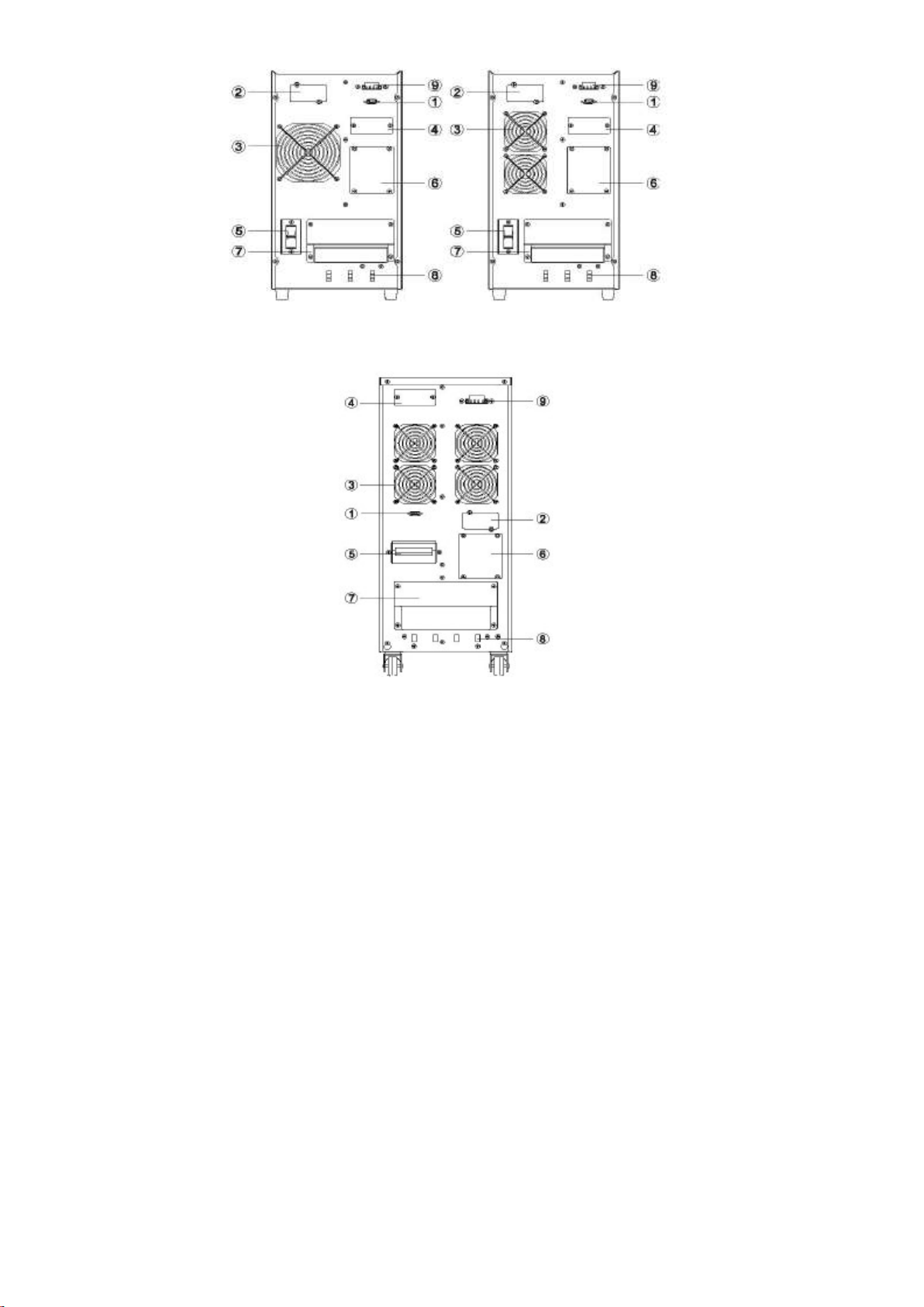
1.3
Real
panel
…………………………………………………………………3
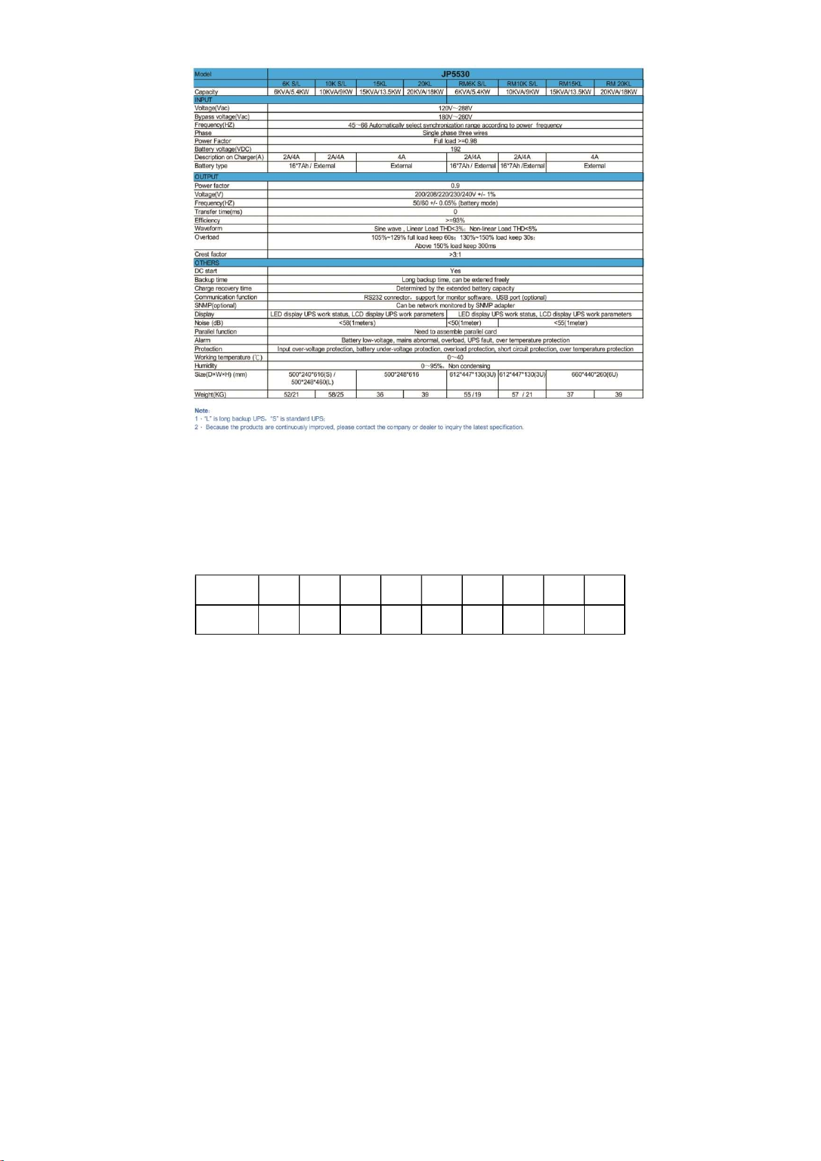
1.4 Spec for product……………………………………………… …………6
2. Installation……… ……………………… ……… …………… …… … ………7
2.1 Checking before using…………………………………………………7
2.2 Table of cable………………………………………………………………7
2. 3
U P S
c o n n e c t i on
… … … … … … … … … … … … … … …… … … … … 8
2.4
Installation
for
external
batte ry……………………………………10
2.5
Connection
to
the
computer………………… … ……………………11
2.6 Parallel(optional)…………………………………………………… ……12
2.7
Installation
for
SNMP(optional)…………………………………………15
2.8 EPO………………………………………………… ……………………16
2.9
Maintenance
switch
(optional)
…………………………………………17
2.10
Dust
screen
(optional)…………………………………………………18
2.11
Isolated
transformer
(optional)………………………………………18
3、Display
panel…………………………………………………………………19
4、O p e r a t i o n …………………………………………………………2 2
4.1 Start UPS on LED panel…………………………………………………22
4.2 Shut off UPS on LED panel……………………………………………23
4.3 Start UPS on LCD panel…………………………………………………24
4.4 Shut off UPS on LCD panel……………………………………………25
5、Battery ……………………………………………………………………
26
6、M a i n t e n a n c e ……………………………………………………………2 7
7、Lights on LED/LCD panel ………………………………………………………28

1
1、 Brief
This UPS serial is sine wave online system with maintenance switch
and
the
function
of
parallel.
It
can
supply
your
equipment
with
good
quality
of
AC
power.
It
can
be
used
for
wide
range
of
areas,
from
computer,
communication
system
to
industrial
area.
Online
UPS
can
supply
the
power
to
the
load
without
any
interruption.
In
case
of
overload
or
the
failure
of
inverter,
UPS
will
switch
to
bypass.
When
overload disappear, UPS will transfer to the inverter automatically.
This user manual can be applied for the following models:
JP5530 6K/RM6K: standard backup type with internal batteries
JP5530 6KL/RM6KL: long backup type with external battery
JP5530 10K/RM10K:standard backup type with internal batteries
JP5530 10KL/RM10KL:long backup type with external battery
JP5530 15KL/RM15KL:long backup type with external battery
JP5530 20KL/RM20KL:long backup type with external battery
For any type of the model customer can select EPO switch,
maintenance
switch
by
hand,
the
user
manual
for
these
two
instruments
is on 2.8 ,2.9.

2
1.1 Spec. for Marks
1.2 Front Panel
Marks and Meaning
Attention
Danger
AC power
DC power
Protective Earth Conductor
Protective Bonding Conductor
Cycling
Not Placed With Other Things
Overload
Battery
On/Off Button
JP5530
6K/10K/15K/20K
JP5530
6
K/10K/15K/20K
JP5530
6KL/10KL
JP5530
6KL/10KL

3
JP5530 RM6K/10K
JP5530 RM15K/20K
1.3 Rear Panel
JP5530 6K JP5530 10K

4
JP5530 6KL
JP5530 10KL
JP5530 1
5/20K

5
① interface for computer
② socket
③ fan
④ parallel card board (parallel card is optional)
⑤ switch for input
⑥ cover panel for maintenance switch(maintenance switch is optional)
⑦ terminal board
⑧ bracket for cable
⑨ EPO(optional)
Please Note:
1.
If
UPS
is
with
parallel
card
and
maintenance
switch,
please
remove
④、⑥ board and you will see the parallel card, maintenance switch.
2. Above picture is for all the models of UPS.
JP5530
RM6K/10K
JP5530 RM15K/20K

6
1.4 Specification
When
input
voltage
is
187V
with
rated
full
load,
and
charger
works
fully,
UPS can have the maximum current.
Load of the high altitude=rated power ×Rating factor(correspond to
altitude)
Altitude
(m) 1000
1500
2000
2500
3000
3500
4000
4500
5000
Rating
Factor 100%
95%
91%
86%
82%
78%
74%
70%
67%

7
Note: If UPS are used when the altitude is above 1000m, must use
Rating Factor to calculate, please read above table.
Danger: Please cut off the switch of mains before installation, if UPS
are long back up type, cut off the input of battery.
Note: 1.Following must be operated by the professional staff
2. Suggest installing UPS falling to the ground.
2、Installation
2.1 Check when open the package
1.
Open
the
package,
and
check
whether
there
is
any
damage
during
the transportation;
2.
If
there
is
any
damage
or
lack
of
some
instruments,
please
contact
with the distributor.
Attachment: A. user manual; B. 6 PCS of terminals.
The package material can be used once more please keep it.
2.2 Table for the cable
Note: Diameter and intersecting surface of the cable are subject to
rated capacity of UPS
In
the
following
table,
L
is
for
there
phase
UPS,
diameter
of
L1、L2、L3
are the same.

8
2.3 UPS connection
Danger: rated input current of the mains switch must be larger than
input
voltage
of
UPS,
otherwise,
mains
switch
will
be
burnt.
(Maximum
input voltage of UPS please review 1.4 table)
1. Select the input/output cable according to the table 2.2;
2. Open the terminal board on the real panel of UPS①;
3. Connect the output cable to the terminal output;
4.
Connect
the
input
cable
to
the
input
terminal,
and
connect
the
battery
cable to the input terminal if batteries need to be connected;
5. Let the cable go through the bracket ②;
6. Fix the input, output and battery cables to the proper position.
Model JP5530
6K/RM6K
JP5530
6KL/RM6KL
JP5530
10K/RM10K
JP5530
10KL/RM10K
L
JP5530
15K/RM15K
JP5530
20K/RM20K
Input
G 10AWG
(6mm 2 )
10AWG
(6mm 2 )
8AWG
(10mm 2 )
8AWG
(10mm 2 )
6AWG
(25mm 2 )
6AWG
(25mm 2 )
N
10AWG
(6mm 2 )
10AWG
(6mm 2 )
8AWG
(10mm 2 )
8AWG
(10mm 2 )
6AWG
(25mm 2 )
6AWG
(25mm 2 )
L 10AWG
(6mm 2 )
10AWG
(6mm 2 )
8AWG
(10mm 2 )
8AWG
(10mm 2 )
6AWG
(25mm 2 )
6AWG
(25mm 2 )
Battery
+ 10AWG
(6mm 2 )
10AWG
(6mm 2 )
8AWG
(10mm 2 )
8AWG
(10mm 2 )
6AWG
(25mm 2 )
6AWG
(25mm 2 )
- 10AWG
(6mm 2 )
10AWG
(6mm 2 )
8AWG
(10mm 2 )
8AWG
(10mm 2 )
6AWG
(25mm 2 )
6AWG
(25mm 2 )
G
10AWG
(6mm 2 )
10AWG
(6mm 2 )
8AWG
(10mm 2 )
8AWG
(10mm 2 )
6AWG
(25mm 2 )
6AWG
(25mm 2 )
Output
L 10AWG
(6mm 2 )
10AWG
(6mm 2 )
8AWG
(10mm 2 )
8AWG
(10mm 2 )
6AWG
(25mm 2 )
6AWG
(25mm 2 )
N
10AWG
(6mm 2 )
10AWG
(6mm 2 )
8AWG
(10mm 2 )
8AWG
(10mm 2 )
6AWG
(25mm 2 )
6AWG
(25mm 2 )
G
10AWG
(6mm 2 )
10AWG
(6mm 2 )
8AWG
(10mm 2 )
8AWG
(10mm 2 )
6AWG
(25mm 2 )
6AWG
(25mm 2 )

9
Danger: when connect the cable, make sure the input/output cable
connect the terminal fasten
Terminal for UPS:
JP5530 6KL/JP5530 6K JP5530 10KL/JP5530 10K
7. Fix the cover-plate with screws again.
8.
Connect
wires
and
get
mains,
then
turn
on
the
Input
Protection
Breaker, and UPS will be power-on.

10
2.4 External Battery Installation of Long-backup Type
JP5530 6-20K Long-backup type apply 16 PCS of 12V batteries (192VDC)
in series into one group and several groups can be in parallel.
Please operate as following steps, otherwise, it may occur electric
shock:
1. Turn off the battery switch and connect batteries in series;
2.
Choose
the
proper
wires
to
connect
the
battery
cabinet
and
UPS
(refer
to
table
2.2).An
air
DC
switch
must
be
connected
between
UPS
and
Battery
groups,
the
voltage
and
current
of
this
switch
cannot be less than parameters on batteries of each model.
Danger: don’t connect UPS firstly.
3.
Connect
the
other
end
of
battery
cable
to
UPS,
UPS
don’t
connect
to
the load, put “ON” button of battery, UPS will charge the battery.
Note: Battery ground on the UPS, the mark is
Model
JP5530
6KL/S
JP5530
10KL/S
JP5530
15KL
JP5530
20KL
Battery Voltage
192VDC
192VDC
192VDC
192VDC
Battery current
34A.max
56A.max
83A.max
112A.max

11
.
2.5 Connect UPS to the computer socket
Socket o f computer: RS232 or USB, will connect the UPS to the monitor.
1 .Connect the RS232 or USB to the socket of computer
2. Connect the RS232 or USB to the socket of UPS
The feet bitmap of computer port on UPS as following:

12
2.6 Parallel card (optional)
1. Introduction
N+X
is
the
most
stable
construction
for
supplying
power,
N
means
minimum
quantity
of
UPS
needed,
X
means
quantity
of
UPS
parallel,
when
X
becomes
larger,
the
system
will
be
more
stable.
3pcs
of
UPS
can be in parallel with parallel cards and cables in this range.
2. Installation for parallel
This
function
is
optional,
the
user
can
buy
parallel
card
and
cable
for
installation,
and
maximum
three
UPS
for
parallel,
each
UPS
must
use
the battery independently
1) Remove
the
board,
install
the
parallel
cable:
connect
the
UPS
by
parallel card and cable.
2)All
the
output
wires
of
parallel
UPS
go
to
one
output
terminal
block,
and then this block will wiring to loads.
Note: Length requirements of
output wires:

13
1)
The
difference
of
each
wire
which
connects
block
and
loads
must
be
less
than
20%
if
the
distance
between
loads
and
every
paralleled
UPS
is
less
than
20
meters.
2)
The
difference
of
each
wire
which
connects
block
and
loads
must
be
less
than
10%
if
the
distance
between
loads
and
every
paralleled
UPS
is
more
than
20
meters.
3)
The
input
and
output
terminals
of
each
paralleled
UPS
should
wire
as
which
in
the
single
UPS,
please
check
the
following
charts.
4)
Every
UPS
in
parallel
should connect a battery group separately.
JP5530 6K-20K parallel picture

14
3. Advantage of parallel
Parallel
can
improve
stability
of
UPS,
when
each
UPS
makes
fault,
the
others
still
can
work,
and
each
UPS
need
maintenance
switch
by
hand.
4. Operation
1)Follow the operation of single UPS.
2)Start UPS in parallel.
Start UPS when mains on: start any one of the UPS, the other UPS
will start working and transfer to inverter.
Start UPS when battery supply power: press button of each UPS for a
short
time,
then
press
any
one
of
the
UPS
for
a
longer
time,
the
other
UPS
will start and work at the battery mode.
3) Shut off UPS in parallel.
Press the button of any one of the UPS more than 4 seconds, to shut off
UPS when parallel; press the button of any one of the UPS more than 1
second, less than 4 seconds to shut off the single UPS.
Note: Press for a long time means more than 1 second, for short time
means less than 0.5 second.

15
2.7 Installation of SNMP (optional)
Install SNMP on the above position of the real panel
1. Take off the board
2. Install SNMP card
3. Fix it using screws
AS400 card (optional)
Install AS400 card to the socket, the position as below:
meaning
PIN1 Break over: UPS fault
PIN2 Break over: alarm
PIN3 Ground
PIN4 Shut off UPS remote control
PIN5 Public terminal non- break over:UPS work
PIN6 Break over:bypass work
PIN7 Break over: low battery voltage
PIN8 Break over:UPS work non break over:bypass work
PIN9 Break over:no power of the mains

16
2.8 EPO
EPO (Emergent
Power
Off
)
,is
on
the
real
panel
of
UPS,
is
green
terminal.
①
1-2 Close, UPS shut off immediately
3-4 Doesn’t work
Other manuals for JP5530 Series
1
This manual suits for next models
6
Table of contents
Other JALpower UPS manuals