JALpower JP9950 User manual

USER’S MANUAL
JP9950-GX 60-400KVA

2
INDEX
SAFETY...................................................................................................................................................................... 4
EMC REQUIREMENTS........................................................................................................................................... 5
STORAGE.................................................................................................................................................................. 5
INSTALLATION ENVIRONMENT......................................................................................................................... 5
PRELIMINARY OPERATIONS.............................................................................................................................. 6
CHECK THE PACKING CASE.................................................................................................................................... 6
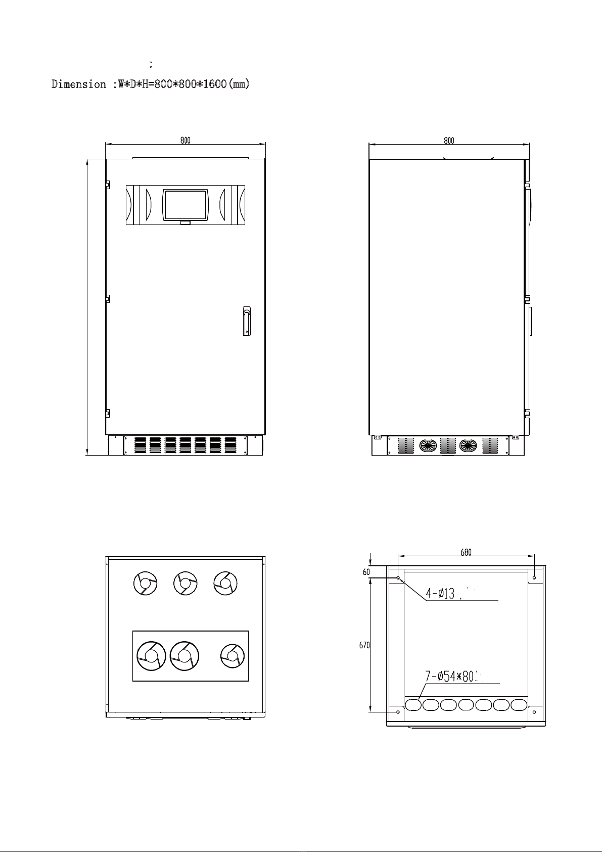
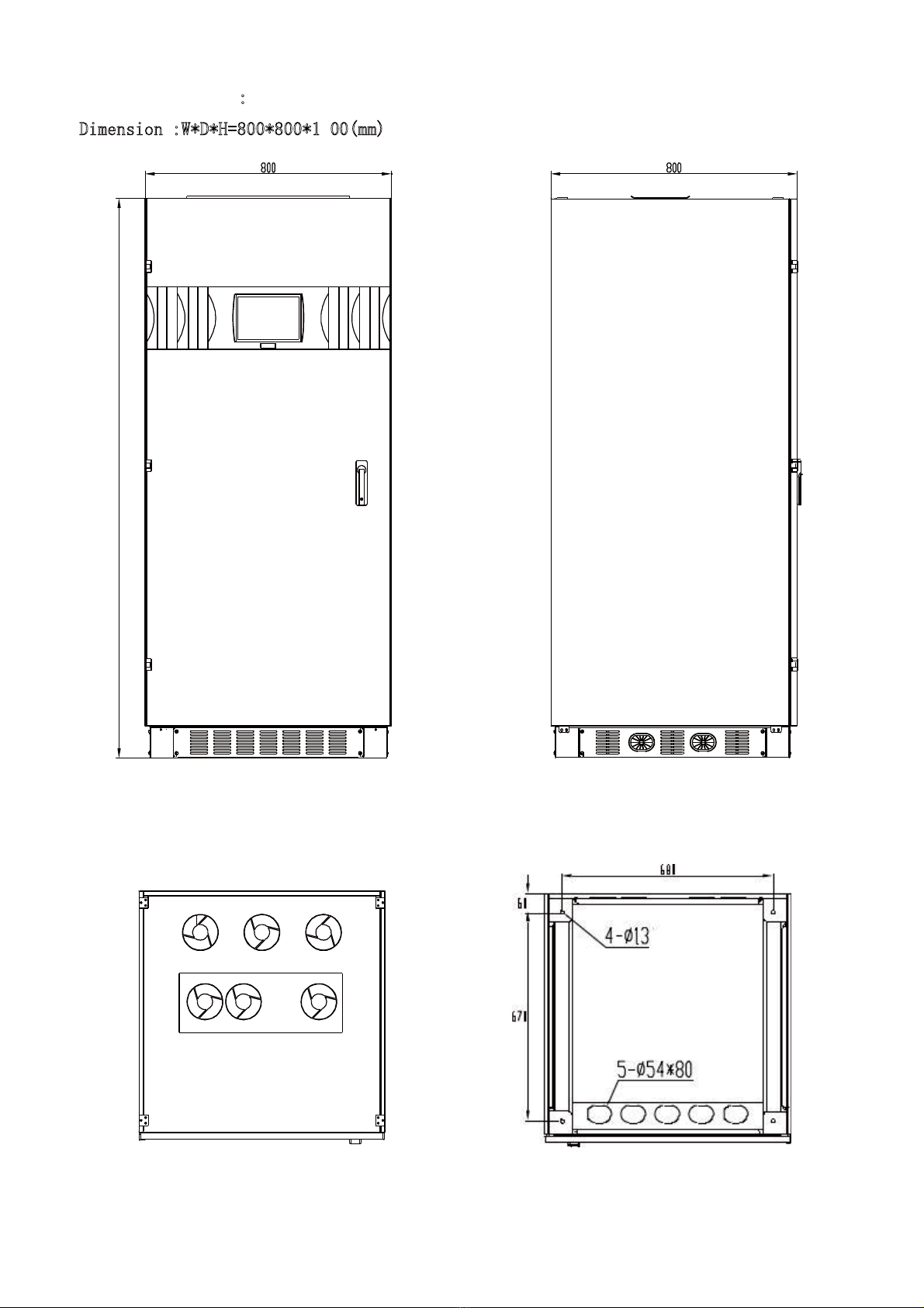
POSITIONING........................................................................................................................................................... 6
SETTING UP THE INPUT/OUTPUT WIRE CONNECTION............................................................................ 12
PROTECTIONS....................................................................................................................................................... 12
Inside the UPS................................................................................................................................................ 12
UPS Input......................................................................................................................................................... 12
UPS output, Short circuits and selectivity................................................................................................... 12
WIRE CONNECTION............................................................................................................................................. 14
START-UP PROCEDURE.................................................................................................................................... 16
FUNCTION CHECK............................................................................................................................................... 16
CUSTOMISATION .................................................................................................................................................. 16
RS232\RS485 COMMUNICATION PORT AND PARALLEL DATA PORT .................................................................. 17
MODES OF OPERATION..................................................................................................................................... 20
NORMAL OPERATION ............................................................................................................................................ 21
BATTERY OPERATION ........................................................................................................................................... 21
OPERATION MODE OF BYPASS............................................................................................................................. 22
BYPASS FOR MAINTENANCE SWMB...................................................................................................................... 23
MAINTENANCE...................................................................................................................................................... 24
SPECIFICATIONS.................................................................................................................................................. 25
HUMAN-COMPUTER TOUCH SCREEN CONTROL PANEL....................................................................... 34
HUMAN-COMPUTER TOUCH CONTROL INTERFACE............................................................................................... 34
HUMAN-COMPUTER TOUCH CONTROL INTERFACE FLOW CHART........................................................................ 35
Luminous warning lights: LED...................................................................................................................... 43
ALARM MESSAGES............................................................................................................................... .............. 44
[1] DISTURBANCES ON BYPASS LINE.................................................................................................... 44
[2] BY-PASS MANUAL, SWMB - ON or cable defect............................................................................... 44
[3] BYPASS VOLT. FAIL or SWBY, FSCR OFF....................................................................................... 44
[4] MAIN LINE VOLTAGE FAIL or SWIN OFF........................................................................................... 44
[5] PREALARM, LOW VOLTAGE ON BATTERY ..................................................................................... 44
[6] BATTERY DISCHARGED OR SWB OPEN.......................................................................................... 44
[7] LOW VOLT. SUPPLY or OVERLOAD [W]............................................................................................ 44
[8] OUTPUT OVERLOAD.............................................................................................................................. 44
[9] BY-PASS FOR VA OUTPUT < AUTO_OFF VALUE.................................................................. 44
[10] INTERNAL FAULT: Number.............................................................................................................. 44
[11] TEMPORARY BYPASS, WAIT............................................................................................................. 45
[12] BY-PASS FOR OUTPUT OVERLOAD (displayed steady or flashing).......................................... 45
[13] BYPASS COMMAND ACTIVE; 8=COMMAND OFF........................................................................ 45
[14] REMOTE BYPASS CONTROL: ACTIVE............................................................................................ 45
[15] OVERTEMPERATURE or FAN FAILURE....................................................................................... 45
[16] INPUT VOLTAGE SEQUENCE NOT OK........................................................................................... 45
[17] OUTPUT OFF, CLOSE SWOUT OR SWMB..................................................................................... 46
[18] SYSTEM OFF COMMAND ACTIVE ; 8=DISACTIVE................................................................. 46
[19] SYSTEM OFF COMMAND ACTIVE; 8=COMMAND OFF. .............................................................. 46
[20] MEMORY CHANGED: CODE = number......................................................................................... 46
[21] AUTO-OFF Timer: T off= 0: 0', T on 0: 0'............................................................................................ 46
MAINTENACE SERVICE...................................................................................................................................... 47
BASIC MENU...................................................................................................................................................... 47
Key menu 1, "?", HELP.................................................................................................................................. 48
KEY MENU 1 : LANGUAGES........................................................................................................................... 48
KEY MENU 2 : VOLTAGE MEASUREMENT................................................................................................ 48
Key menu 2 6 : TIME MEASUREMENT............................................................................................. 49
Key menu 2 2: CURRENT MEASUREMENT.................................................................................... 49
Key menu 2 2 2: 3-PHASE VOLTAGE MEASUREMENT.......................................................... 50
KEY MENU 3 "KEY", COMMANDS................................................................................................................. 50

3
Key menu 3 2: BATTERY TEST............................................................................................................. 50
Key menu 3 4: DISPLAY CONTRAST................................................................................................... 51
Key menu 3 5: CUSTOMIZING............................................................................................................... 51
Key menu 3 5 1: CUSTOMIZING OPERATION IN STANDBY ON (only on enabled UPS)..... 52
Key menu 3 5 2: CUSTOMIZING RATED OUTPUT VOLTAGE ................................................... 52
Key menu 3 5 3: BATTERY CUSTOMIZING................................................................................... 52
Key menu 3 5 4: PREALARM CUSTOMIZING................................................................................ 53
Key menu 3 5 6: AUTO-OFF CUSTOMIZING “VA”........................................................................ 53
Key menu 3 5 6 5 (6): AUTO-OFF Timer CUSTOMIZING........................................................ 54
Key menu 3 5 7 2: BYPASS VOLTAGE RANGE CUSTOMIZING.......................................... 54
Key menu 3 5 7 3: BYPASS FREQUENCY RANGE CUSTOMIZING.................................... 55
Key menu 3 5 7 4 : MODEM CUSTOMIZING....................................................................... 55
Key menu 3 5 7 4 5 (6) : Modem 'Dial /Send' CUSTOMIZING............................................ 56
Key menu 3 5 7 5: RS232 CUSTOMIZING.............................................................................. 56
Key menu 3 5 7 6: ECHO CUSTOMIZING.................................................................................. 56
Key menu 3 5 7 7: IDENT. CUSTOMIZING................................................................................ 56
Key menu 3 6: INVERTER-OFF/BYPASS .......................................................................................... 56
Key menu 3 7: TOTAL SYSTEM SHUT-OFF COMMAND.................................................................. 57
KEY MENU 4: RECORDED EVENTS............................................................................................................. 57
Key menu 4 2 RECORDED VOLTAGES MEASUREMENT................................................................ 58
Key menu 4 2 2: RECORDED CURRENT MEASUREMENT....................................................... 58
Key menu 4 2 2 2: RECORDED 3-PHASE VOLTAGE MEASUREMENT............................. 58
Key menu 4 6: RECORDED CODES..................................................................................................... 58
KEY MENU 5: ACOUSTIC ALARM EXCLUSION.................................................................................................... 58
KEY MENU 6: "CLOCK": DATE/TIME............................................................................................................... 58
KEY MENU 7 "ARROW DOWN": INTERNAL CODES...................................................................................... 59
KEY MENU 8 "ARROW UP": NORMAL........................................................................................................... 60
TABLE OF MEMORIZED INTERNAL CODE.................................................................................................... 61

4
SAFETY
ATTENTION
This manual contains instructions concerning the installation and putting into operation
of the UPS. Read the manual carefully before carrying out installation, which must be
done by a trained person.
Because this manual contains essential information on the usage of the equipment, it
must be kept in a safe place and consulted before operating on the UPS.
SAFETY REGULATIONS
The ups must not be used unless it is connected to earth
The first connection to make is the connection between the grounding lead and
the terminal indicated with the symbol:
All maintenance operations inside the ups must be carried out only by trained
personnel.
High voltages are present inside the equipment even when the input and battery
switches are open
If it is necessary to replace the fuses, they must be replaced with other fuses of the
same type (consult paragraph “set output wire connection”).
To interrupt the power supply to the utilities in dangerous conditions, open all the
switches located behind the front door, or switch on the" system off " command on the
ups from the control panel.
THE BATTERY SHOULD BE CHANGED IF NECESSARY ONLY BY QUALIFIED
PERSONNEL. TO ELIMINATE REPLACED PARTS IT IS OBLIGATORY TO
DELIVER THEM TO ONE OF THE SPECIAL CONSORTIUMS FOR DISPOSAL
BY RECYCLING. THE BATTERIES ARE CLASSIFIED TOXIC WASTE BY LAW.
The Company reserves the right to make changes to the product described in this
manual at any time and without notice for reasons of improvement.

5
EMC REQUIREMENTS
Uninterruptible Power Supply (UPS) "UPS" models, marked CE and used following
the instructions listed below, have the essential requirements to comply whit the
EMC directive 89/336 e 92/31 a 93/68 ECC.
Usage instructions
The "UPS" are UPS dedicated to a professional usage in an industrial and
commercial environment.
The connection to "REMOTE" and "RS232" connectors must be done by means of
a shielded cable.
WARNING: The " UPS " standard is a Class A-UPS Product.
In a domestic environment, this product may cause radio interference, in
which case, the user may be required to take additional measures.
STORAGE
For instance: in case of disturbances received by a radio or a television set, the
UPS shall be moved in order to increase the distance from above mentioned
devices.
The area used to store the equipment must have the following characteristics:
Temperature: 0°-40°C (32°-104°C)
Relative humidity: 95% max
Only for UPS with internal BATTERIES.
The batteries contained in the UPS are subject to self-discharging.
If the UPS is not immediately installed is necessary to take note of the batteries date recharge printed on
the label fixed to the packing case(the date is present only if the UPS contains to its inside batteries), and
provide to it recharges within such date.
To recharge batteries just power up the UPS and leave it on NORMAL OPERATION for at least 24
hours.
INSTALLATION ENVIRONMENT
When choosing a suitable installation room, take note of the following:
avoid dusty areas, or other kinds of dust in air.
check that the floor is strong enough to support the weight of the UPS and the battery cabinet
(see paragraph "DIMENSIONS AND WEIGHTS")
avoid rooms that are too narrow as this could make normal maintenance operations difficult
check the ambient temperature when the UPS is running. It should be between 0 and 40°C.
The UPS is able to function in an ambient temperature of between 0 and 40°C. The
recommended operating temperature for the UPS and the batteries is between 20 and
25°C. In fact, the average operating life of the batteries is 4 years at an operating
temperature of 20°C, but if the operating temperature is increased to 30°C the life is

6
halved.
do not position the machine in areas exposed to direct sun light or hot air.
In order to keep the temperature of the installation room within the field of values mentioned above, it will
be necessary to install a system for eliminating dissipated heat (the value of the kcal/kW/B.T.U.
dissipated by the UPS is indicated in the paragraph "SPECIFICATIONS ”).
The following methods can be used:
natural ventilation;
forced ventilation, recommended if the exterior temperature is lower (e.g. 20°C) than the
temperature at which you wish to run the UPS (e.g. 25°C);
air conditioning system, recommended if the exterior temperature is higher (e.g.s.30°C) than the
temperature set for running the UPS (e.g.s.25°C).
PRELIMINARY OPERATIONS
CHECK THE PACKING CASE
When you receive the UPS check that the packing case has not
been damaged during transportation.
Check that neither of the two anti-shock devices fixed to the
packing case has become red. If this has happened follow the
instructions given
on the packing case.
Be careful when removing the packing materials so as not to scratch the UPS cabinet.
The equipment must be handled with care as it could be damaged if it is dropped or banged.
The UPS is delivered with:
guarantee
user instruction manual
battery fuses (if battery are present).
POSITIONING
You should bear in mind the following points when positioning the UPS:
a space of at least one metre must be kept in front of the machine to leave plenty of room for
maintenance operations.
a space of at least 20 cm. must be left between the back of the UPS and the wall so as not to block
the flow of air from the fans, and at least 40 cm. for maintenance operations on the fans.
no objects must be placed on the top of the machine.
The AC-DC INPUT/OUTPUT cables may enter from the bottom or from the back of the UPS.
MOVIMENTAZIONE CON IMBALLO / HANDLING WITH PACKING
1000
RIMOZIONE DEL PALLET / TO REMOVE THE PALLET
1000

7
UPS 6
0~80KVA :
Dimension :W*D*H=800*800*1 (mm)
weivediSweivtnorF
weivmottobfonoitallatsnIweivpoT
1600

8
1600
UPS
100~120KVA :
Dimension :W*D*H=800*800*1600(mm)
weivediSweivtnorF
Top view Installation of bottom view

9
Installation of bottom view
UPS
160~200KVA:
Dimension :W*D*H=1100*800*1800(mm)
Front view Side view
Top view

10
2000
1100
949 81
UPS
250~300KVA:
Dimension :W*D*H=1400*1100*2000(mm)
1400 1100
Front view Side view
1400
Top view Upward view

11
2000
1100
949
UPS
350~400KVA:
Dimension :W*D*H=1600*1100*2000(mm)
1600 1100
Front view Side view
1600
Top view

12
SETTING UP THE INPUT/OUTPUT WIRE CONNECTION
PROTECTIONS
Inside the UPS
The size of the switches and fuses installed on the UPS input/output lines are given below (consult the block
diagrams paragraph for the initial). A fuse must always be replaced by a fuse of the same capacity and with
the same characteristics as those mentioned in the table.
UPS: 60-200KVA
Internal
protection
UPS
Typ
e
Breakers Breakers Battery fuses STS fuses Max current . Output
current
[kVA] Input rectifier Bypass
input
SWOUT/
SWMB Battery [A] [A]
SWIN
SWBY SWOUT/SWMB FUSE-BAT FUSE-SCR Nominal
60 100A(3P) type C 100A(3P) type
C
100A(3P) type C 160A 32A (gG)
10x38 108 72
80 125A(3P) type C 125A(3P) type
C
125A(3P) type C 200A 32A (gG)
10x38 144 96
100 200A(3P) type C 200A(3P) type
C
200A(3P) type C 280A 200A 180 120
120 225A(3P) type C 225A(3P) type
C
225A(3P) type C 320A 250A 216 144
160 250A(3P) type C 250A(3P) type
C
250A(3P) type C 400A 300A
400A
288
360
192
240
200 350A(3P) type C 350A(3P) type
C
350A(3P) type C 500A 400A 360A 240A
UPS:250-400KVA
Internal
protection
UPS
Typ
e
Breakers Breakers Breakers STS fuses Max current Output
current
[kVA] Input rectifier Bypass
input
SWOUT/SWMB Battery [A] [A]
SWIN SWBY SWOUT.SWMB SWBAT FUSE-SCR Nominal
250 400A(3P) 400A(3P) 400A(3P) 630A(2P) 400A 400 300
300 630A(3P) 630A(3P) 630A(3P) 6300A(2P) 630A 480 360
350 630A(3P) 630A(3P) 630A(3P) 630A(2P)
800A(2P)
630A
630A
560
640
420
480
400 630A(3P) 630A(3P) 630A(3P) 800A(2P) 630A 640 480
UPS Input.
When selecting the protections to install at the input of the continuity group, you must take into consideration
the maximum current absorbed in the two operating conditions:
In "NORMAL OPERATION", from the main line via the rectifier, the “max input current” is the one
indicated in the table. The automatic breaker is present at the rectifier input, as shown in the table,
"SWIN".
In "BY-PASS OPERATION", straight from the by-pass line, the max. value of the current is restricted by
intervention of the “automatic breaker SWBY”.
UPS output, Short circuits and selectivity
Nominal current, Input/output from the UPS is the one indicated in the table "output current".
Short circuit
When a fault occurs on the load, i.e. a short circuit, the UPS protects itself by restricting the value and the
duration of the supplied current (short circuit current). These values also depend on the operating status of
the unit at the time of the fault. We must distinguish between two situations:

13
UPS in NORMAL OPERATION
the load is immediately switched onto the by-pass line, guaranteeing, before the fuses intervene,
the circuit current values indicated in “SPECIFICATION BY_PASS LINE” paragraph.
UPS in BATTERY OPERATION
The UPS protects itself by supplying an output current approximately double the nominal current
for 0,1s.
Output breakers Selectivity
In NORMAL OPERATION : selectivity is carried out with a type Gg fuse to protect
if you want to guarantee selectivity when operating by battery ,output fuse must be installed.
Three phase output UPS:60-80KVA
[KVA] 60 80
Max current fuse Gg in ups output [A]
1)For selectivity in “BATTERY OPERATION ”
2)For selectivity in “NORMAL OPERATION”
80
100
100
125
Three phase output UPS:100-200KVA
[KVA] 100 120 160 200
Max current fuse Gg in ups output [A]
1)For selectivity in “BATTERY OPERATION ”
2)For selectivity in “NORMAL OPERATION”
125
160
160
200
200
250
250
300
Three phase output UPS:250-400KVA
[KVA] 250 300 350 400
Max current fuse Gg in ups output [A]
1)For selectivity in “BATTERY OPERATION ”
2)For selectivity in “NORMAL OPERATION”
300
350
350
400
400
450
450
500
Leakage current circuit breaker
In the standard version, where there is no separation transformer on the by-pass line, the neutral output from
the mains is connected to the output from the UPS.
*When input neutral connected to output neutral, the electrical systems located upstream and
downstream of the ups are identical
When operating in the presence of mains voltage, a differential breaker installed at the input intervenes
because the output circuit is not isolated from the input circuit.
When operating without mains voltage (battery feeding) the input differential breaker intervenes only if it is
able to switch on as a result of leakage current without voltage at its poles (for example a differential with an
auxiliary relay is not suitable).
The differential switch located upstream must have the following characteristics:
a minimum differential current of 300mA (to avoid inappropriate
interventions)
class A or class B
delay greater or equal to 0,1s

14
WIRE CONNECTION
The following operations are to be performed with the UPS disconnected from the mains and all the
equipment switches open.
CAUTION! THE FIRST CONNECTION TO MAKE IS THE GROUNDING LEAD TO THE TERMINAL
MARKED 'PE'.
THE UPS CANNOT OPERATE WITHOUT CONNECTION TO THE GROUNDING SYSTEM.
UPS connection
Single power input
When rectifier input and bypass input share one mains input,the following picture,the jumper should be
installed before leaving factory,mains input connects IN/L1 ,IN/L2,IN/L3 ,N,loads connect
OUT/L1,OUT/L2,OUT/L3,N.
Dual power input
When rectifier input uses one mains input,bypass input uses another mains input,the jumper should be
removed between IN/L1 and BY/L1,IN/L2 and BY/L2,IN/L3 and BY/L3,one mains input connects
IN/L1 ,IN/L2,IN/L3 ,N,another mains input connect BY/L1,BY/L2,BY/L3,N.Loads connect
OUT/L1,OUT/L2,OUT/L3,N.
Use the appropriate wire diameter properly to install correctly. (between brackets max. wire size):

15
Wire diameter [mmq]
input output battery
kVA L1/L2/L3/N PE L1/L2/L3/N +/-
60 35 16 35 50
80 35 16 35 50
100 50 25 50 70
120 50 25 50 70
160 70 25 70 95
200 70 25 70 95
250 95 25 95 120
300 120 25 120 150
350 150 25 150 185
400 185 25 185 240
Check connections
After connecting the INPUT/OUT and terminal wires to the terminals of the UPS and before repositioning the
switch covers panel, check to make sure that:
all the input/output terminals are tightly screwed;
all fuse holders have a fuse inserted and are in the closed position;
the input/output protection wire (yellow/green earth wire) is correctly connected
the internal panel panel is connected to the yellow/green uni-potential cable coming from the earth bar
located on the base of the equipment.

16
16
START-UP PROCEDURE
After completing the electrical connection as indicated above and putting the internal panel into position,
proceed to start up the UPS as follows:
- Input power line
To activate all switch on the input terminal block
- Battery cabinet
To activate battery cabinet switches (first check the polarity of the connection),
- UPS
To activate the following UPS switches:
SWIN Input switch,
SWBY By-pass line switch,
SWOUT Output switch.
NOTE: the SWMB switch must be left open during normal operation. The SWMB is closed only in order to
directly feed the mains load excluding the UPS, e.g. for maintenance purposes,After you have carried out the
above-mentioned operations, you will hear the hum of the fans immediately, and for about one minute, ups
will transfer into inverter.
FUNCTION CHECK
After completing the start-up operations and waiting for at least four hours to allow the batteries to charge,
with the UPS in normal operation,open the input switch,input status light on the flow chart of LCD display will
become gray.the discharging indicates window of the battery will become green,checking output of ups is
normal,in this condition,turn off the mains input,then battery offers power to UPS.After several minutes,close
the input switch,ups will be back into normal status,the indicating window of AC input on the display panel will
become green.Meanwhile ,the re-charging of the batteries will happen automatically.
CUSTOMISATION
By inserting the access code 436215 on the maintenance menu of display interface, it is possible to alter
some of the electric parameters pre-set in the factory
It is possible to customise the following values:
- value of the NOMINAL OUTPUT VOLTAGE,
- voltage field and the frequency of acceptance on the BY-PASS line,
- BATTERY parameters, pre-alarm for final battery discharge,
- power shut-off lower than a set value (AUTO-OFF power),
- daily scheduled shut-off (AUTO-OFF time)

17
RS232\RS485 COMMUNICATION PORT AND PARALLEL DATA PORT
- In the left of input/output terminal,communication port and parallel data port are as below:
RS232 communication port
UPS connects computer:
UPS
Computer terminal
P1, 9 pole female P2, 9 pole female(computer)
pin 2 Send to pin 2
Pin 3 Receive to pin 3
Pin 5 End to pin 5
Defaultsetting :9600 baud, -no parity, -8bit, -1 bit of stop
RS485 communication port
Baud rate:9600 baud
P1, 9 pole female
pin 9 A
Pin 8 B
MODBUS communication protocol
This serial inverter offer RS485
port communicate with computer,adopts
Modbus as interface protocol,and
support MODBUS RTU protocol
Register definition:adopt commander 4
To check
Default modbus address:1
Baud rate: 9600
Data bite:8
Stop bite:1
Parity bite:No parity

18
Modscan setting
When you open Modbus,please set the following option:
a、display start address is set to 0001
b、display data length is set to 51
c、the Device id of Modbus is set to 1
d、click drop-down menu options 04:INPUT REGISTER
MODBUS address data query table
0Main power input frequency Fin Word(2Byte) HT-L0 0.1Hz
1Main power input line voltage Vrs Word HT-L0 0.1V
2Main power input line voltage Vst Word HT-L0 0.1V
3Main power input line voltage Vtr Word HT-L0 0.1V
4Main power input phase voltage Vr Word HT-L0 0.1V
5Main power input phase voltage Vs Word HT-L0 0.1V
6Main power input phase voltage Vt Word HT-L0 0.1V
7Rated charging current A Word HT-L0 A
8Main power input phase capacity Sin Word HT-L0 0.01kVA
9AC output frequency Fr Word HT-L0 0.1Hz
10 AC output line voltage Vrs Word HT-L0 0.1Hz
11 AC output line voltage Vst Word HT-L0 0.1Hz
12 Output line voltag Vwu Word HT-L0 0.1V
13 AC output phase voltage Vr Word HT-L0 0.1V
14 AC output phase voltage Vs Word HT-L0 0.1V
15 AC output phase voltage Vt Word HT-L0 0.1V
16 AC output phase current Ir Word HT-L0 0.1A
17 AC output phase current Is Word HT-L0 0.1A
18 AC output phase current It Word HT-L0 0.1A
19 Output phase capacity Su Word HT-L0 0.1kVA
20 Output phase capacity Sv Word HT-L0 0.1kVA
21 Output phase capacity Sw Word HT-L0 0.1kVA
22 Total output capacity Stotal Word HT-L0 0.1kVA
23 Output capacity percentage PSr Word HT-L0 0.1
24 Output capacity percentage PSs Word HT-L0 0.1
25 Output capacity percentage PSt Word HT-L0 0.1

19
Address Define Type Format Unit
26 Bypass frequency FBYP Word HT-L0 0.1Hz
27 Bypass input line voltage Vbrs Word HT-L0 0.1V
28 Bypass input line voltage Vbst Word HT-L0 0.1V
29 Bypass input line voltage Vbtr Word HT-L0 0.1V
30 Bypass input phase voltage Vbr Word HT-L0 0.1V
31 Bypass input phase voltage Vbs Word HT-L0 0.1V
32 Bypass input phase voltage Vbt Word HT-L0 0.1V
33 DC chain voltage Vdc Word HT-L0 0.1V
34 Battery voltage Vbat Word HT-L0 0.1V
35 Remaining percentage of battery power Word HT-L0 0.1
36 Battery charging current Ic Word HT-L0 0.1A
37 Empty
38 Rectifier temperature Word HT-L0 0.1℃
39 Internal temperature of ups Word HT-L0 0.1℃
40 Empty
41 Inverter temperature Word HT-L0 0.1℃
42 Percentage of input voltage A phase Word HT-L1 0.1
43 Percentage of input voltage B phase Word HT-L2 0.1
44 Percentage of input voltage C phase Word HT-L3 0.1
45 Percentage of input current A phase Word HT-L4 0.1
46 Percentage of input current B phase Word HT-L5 0.1
47 Percentage of input current C phase Word HT-L6 0.1
48 Input A phase current Word HT-L7 0.1
49 Input B phase current Word HT-L8 0.1
50 Input C phase current Word HT-L9 0.1

20
MODES OF OPERATION
BLOCK DIAGRAM
Other manuals for JP9950
1
This manual suits for next models
1
Table of contents
Other JALpower UPS manuals
Popular UPS manuals by other brands

Maruson
Maruson TACOMA LV Series user manual

MGE UPS Systems
MGE UPS Systems Evolution 2000 RT 2U Installation and user manual

AEG
AEG Protect Home operating instructions

Best Power
Best Power Patriot 250 VA user guide

Precision Power
Precision Power PP36L-12K-3 user manual

Eaton
Eaton Power Xpert PXGX Quick start instructions

Astrid
Astrid UPS HALLEY/E Series product manual

CyberPower
CyberPower CyberShield CSN75A12V3 user manual

Tripp Lite
Tripp Lite SMART 2200 NET owner's manual

Toshiba
Toshiba 1600 Series instruction manual

Tycon Power Systems
Tycon Power Systems UPS-AL48-180-900 Quick install guide

ARMAC
ARMAC HOME LITE 650/LED/V2 user guide