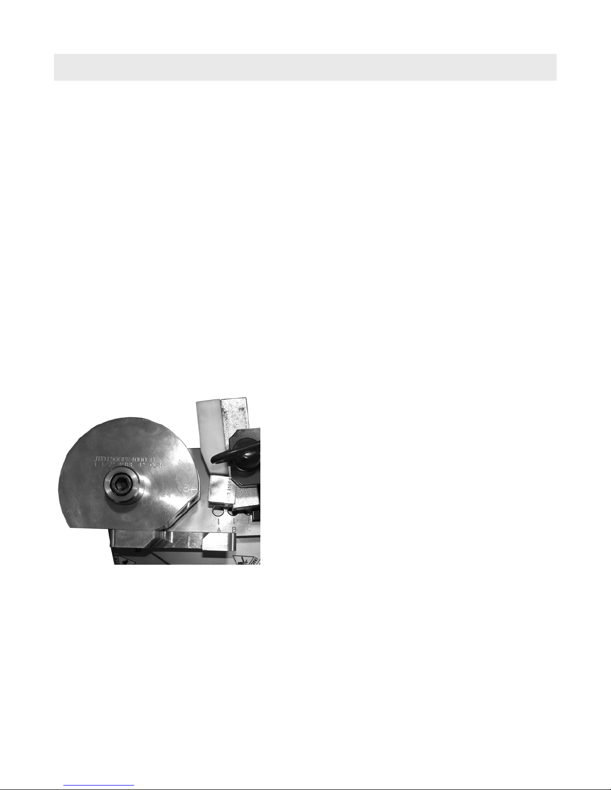
Jancy Engineering JB2400 User manual

Jancy JB2400 Bender
OPERATOR’S MANUAL
EYE PROTECTION
REQUIRED
LINE VOLTAGE
PRESENT
NEVER PLACE
FINGERS NEAR
MOVING PARTS
MODEL #JB2400
Serial # Date of Purchase
WARNING!
before use, be sure everyone using this machine reads and understands
all safety and operating instructions in this manual.

Jancy JB2400 Bender
Congratulations on your purchase of a Jancy Slugger pipe/tube bending machine. Slugger machines are
designed to deliver years of dependable service. Please take a moment to complete and mail your warranty reg-
istration card. Doing so will validate your machine’s warranty period and ensure prompt service if needed. Thank
you for selecting a Slugger product from Jancy Engineering.
table of contents
IMPORTANT SAFETY INSTRUCTIONS . . . . . . . . . . . . . . . . . . . . . . . . . . . . 3
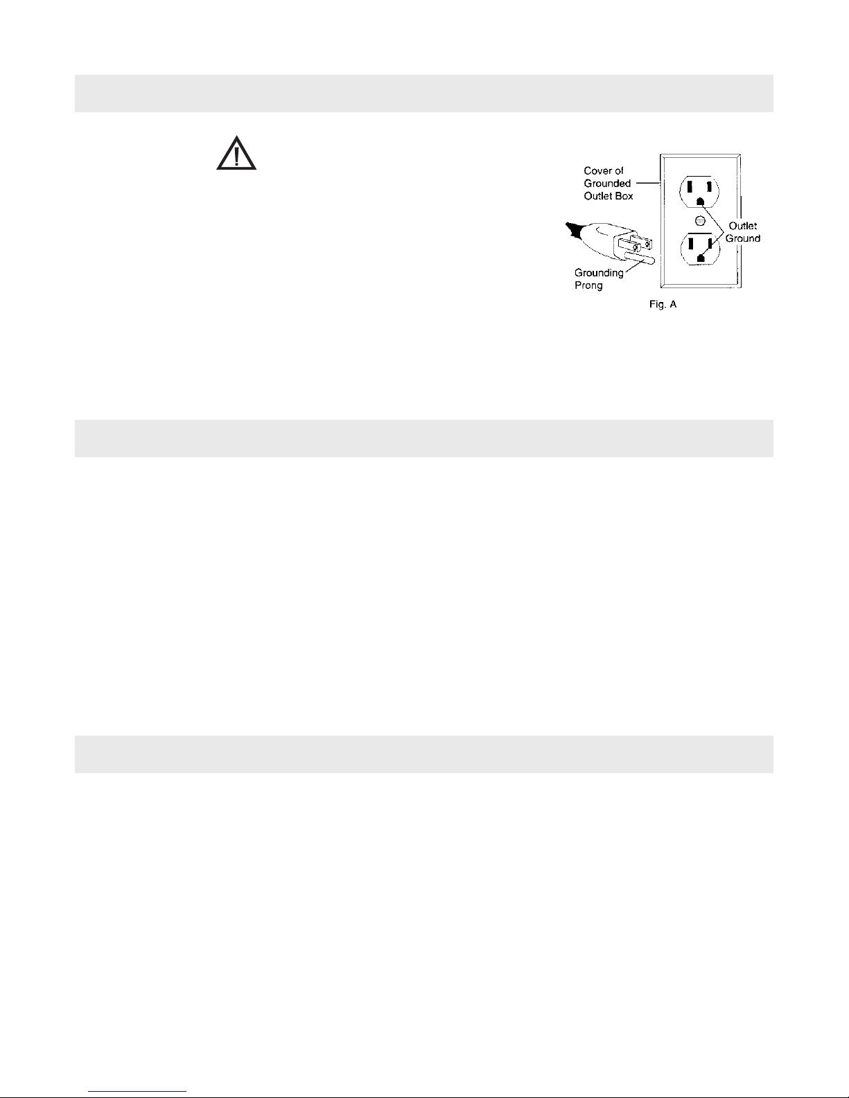
GROUNDINGINSTRUCTIONS...................................5
POWERSUPPLY..............................................5
EXTENSIONCORDS...........................................5
GETTINGSTARTED ...........................................6
OPERATINGINSTRUCTIONS....................................7
TURNINGONTHEPOWER.....................................7
FORM DIE ASSEMBLY INSTALLATION . . . . . . . . . . . . . . . . . . . . . . . . . . . . 7
PRESSURE DIE ASSEMBLY INSTALLATION. . . . . . . . . . . . . . . . . . . . . . . . 7
MAKINGABEND..............................................8
MAINTENANCE & TROUBLESHOOTING. . . . . . . . . . . . . . . . . . . . . . . . . . . 9
APPENDIX A: BEND QUALITY AND TROUBLESHOOTING . . . . . . . . . . . 10
APPENDIX B: COMMON PIPE AND TUBE BENDING TERMS . . . . . . . . . 11
PARTSBREAKDOWN.........................................12
PARTSLIST.................................................14
MAINTENANCERECORDS ....................................15
JANCY ENGINEERING RESERVES THE RIGHT TO MAKE
IMPROVEMENTS AND MODIFICATIONS TO DESIGN WITHOUT PRIOR NOTICE.
limited warranty
Jancy Engineering Inc. will, within eighteen (18) months from the date of purchase, repair or replace any goods
found to be defective in material or workmanship, provided the product warranty registration card has been returned
to Jancy Engineering Inc. within thirty (30) days of purchase date. This warranty is void if the item has been dam-
aged by accident, neglect, improper service, or other causes not arising out of defects in materials or workmanship.
This warranty does not apply to machines and/or components which have been altered, changed, or modified in
any way, or subjected to use beyond recommended capacities and specifications. Electrical components are sub-
ject to respective manufacturers’ warranties. All goods returned defective shall be returned prepaid freight to Jancy,
which shall be the buyer’s sole and exclusive remedy for defective goods. In no event shall Jancy Engineering be
liable for loss or damage resulting directly or indirectly from the use of merchandise or from any other cause. Jancy
Engineering is not liable for any costs incurred on such goods or consequential damages. No officer, employee, or
agent of Jancy is authorized to make oral representations of fitness or to waive any of the forgoing terms of sale
and none shall be binding on Jancy.
2

important safety instructions
WARNING!
when using electric tools, basic safety precautions should always be followed to reduce
the risK of fire, electric shocK, and personal inJury.
READ AND SAVE ALL INSTRUCTIONS FOR FUTURE REFERENCE.
1. Keep Work Area Clean
•Cluttered areas and benches invite injuries.
2. Consider Work Area Environment
•Do not expose power tools to rain.
•Do not use power tools in damp or wet locations.
•Keep work area well lit.
•Do not use tool in presence of flammable liquids or gases.
3. Guard Against Electric Shock
•Prevent body contact with grounded surfaces. For example: pipes, radiators, ranges and refrigerator
enclosures.
•Disconnect from power source when not in use.
•Never use if electrical cord is damaged or wet.
•Always keep electrical cord clear of rotating parts and belt while in motion.
4. Keep Children Away
•Do not let visitors contact tool or extension cord.
•All visitors should be kept away from work area.
5. Dress Properly
•Do not wear loose clothing or jewelry. They can be caught in moving parts.
•Non-skid footwear is recommended when working outdoors.
•Wear protective hair covering to contain long hair.
6. Use Safety Glasses
•Also use face or dust mask if cutting operation is dusty. Everyday eyeglasses only have impact resistance
lenses, they are NOT safety glasses.
7. Wear a Dust Mask
•Some dust created by grinding activities contains chemicals known to cause cancer, birth defects or other
reproductive harm. Provide adequate ventilation.
8. Keep All Guards in Place
•Keep all guards in place and in working order.
9. Avoid Contacting Moving Parts
10. Secure The JB2400 Bender
•Lock the casters and chock the wheels to prevent machine from moving when in use.
11. Before Servicing
•Disconnect the power supply before servicing the machine.
3

12. Reduce The Risk of Unintentional Starting
•Make sure switch is in the off position before plugging in.
13. Never Leave Tool Running Unattended
•Turn power off. Don’t leave tool until it comes to a complete stop.
14. Handle Work Material with Caution
•Wear leather gloves when handling work pieces.
Sharp edges and burrs can cause personal injury.
• Support long pieces of material through bend.
15. Don’t Force Tool
•It will do the job better and safer at the rate for which it was designed.
16. Don’t Over Reach
•Keep proper footing and balance at all times.
17. Do Not Use Damaged Tooling
•Tooling that shows signs of wear or is damaged should be replaced before continuing use.
18. Install Tooling in Correct Orientation
•Install Form Die Assembly with Clamp Arm towards long bending arm.
• Install Pressure Die Assembly with bronze end towards clamping arm.
• See diagram below (Figure #1, below).
19. Keep Jancy Bender Properly Maintained
•Ensure that sufficient hydraulic fluid is in the reservoir (at least 3.5 gallons of Mobile DTE 24 or equal,
100 SUS - 350 SUS at 100oF).
• Inspect hoses and fittings for cracks and leaks. Repair or replace before operating machine.
• Grease main pivot assembly after every 40 hours of use.
20. Only Use Recommended Fluids and Accessories
•Use only approved fluids and lubricants on this machine (refer to page 9).
• Consult the owner’s manual for recommended accessories. The use of improper accessories may cause
injury to persons.
IMPORTANT: KEEP THESE INSTRUCTIONS FOR FUTURE REFERENCE
important safety instructions
Fig. 1
4

WARNING!
Improperly connecting the grounding wire can result in the risk of electrical
shock. Check with a qualified electrician if you are in doubt as to whether
the outlet is properly grounded. Never remove the grounding prong from
the plug. If the cord or plug is damaged, have it repaired before using. If the
plug does not fit the outlet, have the proper outlet and/or plug installed by
a qualified electrician. The Jancy Slugger Bender must be plugged into an
appropriate outlet, properly installed in accordance with all codes and ordi-
nances. The plug and outlet should look like those in Figure A.
grounding instructions
Use only 3-wire extension cords, that have 3-prong grounding-type plugs and 3-pole receptacles that accept
the machine’s plug. Replace or repair damaged cords before use. Make sure your extension cord is in good
condition. When using an extension cord, be sure to use one heavy enough to carry the current your product
will draw. An undersized cord will cause a drop in line voltage resulting in loss of power and overheating the
machine. Jancy recommends using a minimum 12 gauge extension cord not to exceed 50 feet.
extension cords
This machine is designed to run on either 110 or 220 volts. Operating this machine on voltage other than that
stated on the machine will increase the risk of fire, and/or personal injury.
110 Volt machines must be plugged into a circuit that is controlled by a minimum 25 Amp circuit breaker.
220 Volt machines must be plugged into a circuit that is controlled by a minimum 15 Amp circuit breaker.
Failure to use the minimum rated circuit breakers will increase the risk of fire, and/or personal injury.
power supply
5

CAUTION!
always disconnect Jancy slugger bender from power source before maKing adJustments.
WARNING: Ensure the Jancy Slugger Bender switch is in the off position before plugging in the
power lead to the power outlet. Ensure the power cable is not in a position where it can come into
contact with any moving parts of the Jancy Slugger Bender.
WARNING: Jancy Bender weighs approximately 600 pounds, use care in handling machine.
WARNING: Do not insert forks into cabinet to load or unload the machine. Doing so may cause damage
to machine components.
- Remove all packaging material and shipping bands that secure the machine to the pallet.
There are two methods for removing the machine from the shipping pallet.
Method #1(preferred method):
Remove the two 2X6 support boards from under the machine by removing the screws at both ends.
With some assistance, raise the machine slightly to remove the remaining two 2X6 boards.
If possible, build a ramp at the front of the machine.
With some assistance, roll the machine off of the pallet using caution not to drop it to the ground or onto
anyone's feet or hands.
Method #2:
Lift machine off of pallet by using a forklift, or overhead lift, etc.
Position a single lifting strap around the upper box tube at the front end of
the machine (as pictured).
ONLY RAISE THE MACHINE HIGH ENOUGH TO REMOVE THE PALLET,
SET THE MACHINE ON THE GROUND AS SOON AS POSSIBLE.
Alternatively: Remove the two middle 2X6 boards from under the machine
by removing the screws at both ends. Position the forks under the lower frame. Only lift the machine
high enough to remove the shipping pallet.
Have a qualified electrician install the appropriate power connector to the end of the
power cord.
Remove all contents from packaging and inspect to ensure no damage was incurred during shipping. Your JB2400
package should also include the following:
operating instructions (before you begin)
description part # qty
operator’s manual LIT115 1
5/8” allen Wrench JB000108 1
3/32" allen Wrench 0070092 1
3/4" X 6" HITCH PIN JBL26169 1
Jancy White grease JB0810 1
pressure Die cam control hanDle 0151333 2
getting started
Additional Jancy White Grease in a can can be
purchased by the can (#JB0810) or 12 can case (#JB0811)
Attach lifting strap as pictured
6

operating instrucions
The Jancy Bender is designed to accommodate a wide variety of tube and pipe diameters and wall thicknesses.
To ensure a quality bend, use the appropriate sized tooling for the material being bent. Example: 1.50” pipe is
1.90” OD, where as 1.50” tube is 1.50” OD. In most cases a Center Line Radius (CLR) of three (3) times that of
the outer diameter should be used. See Appendix A of more information on bend quality and troubleshooting.
The Jancy Bender is fitted with a lockable master switch. It is recommended that the switch is locked when not
in use to prevent untrained or unauthorized use of the machine.
Turning on the power
- Rotate the main power switch handle clockwise to the “ON” position.
- To turn the machine off, rotate the handle counter clock-wise to the “OFF” position.
Form die assembly installation
Caution!
The forming dies can be extremely heavy. Use assistance or mechanical means to lift the larger form dies
into position.
Caution!
Do not drop the form dies, damage to the machine and/or personal injury may result.
- Install form die over the central locating pin.
- Rotate die until all of the smaller drive pins are engaged, lower form die completely.
Pressure die assembly installation
- Remove the pressure die pull handle.
- Position the pressure die assembly in the opening of the pressure die pivot, with the bronze pressure die
towards the clamp arm. Insert pull handle into the pressure die pivot assembly.
- To re-position pressure die pivot assembly, loosen and remove the three (3) 3/4-10 SHCS that hold the pressure
die base to the upper bending arm.
- Insert test material into the clamp arm, and rotate the pressure die assembly into place.
- With the “cam” handle in the full rearward position, position the pressure die assembly approximately 1/4” - 3/8”
from the form die.
- Locate the threaded holes in the upper bending arm just behind the bolt holes in the pressure die base. Position
the pressure die pivot assembly over these holes and install and tighten the two (2) 3/4-10 x 1.50” SHCS. Insert
the 3/4- 10 x 7.50” SHCS into the “cam” assembly, do not tighten yet.
- Rotate the “cam” assembly until the pressure die barely touches work piece, but allows the pressure die
assembly to beswung out of position. Tighten the 3/4-10 x 7.50” SHCS.
7

WARNING: Before powering up the machine, ensure that all moving parts are clear
of obstructions, all bolts have been secured, and that the control lever is in the
center/neutral position.
- Ensure that the appropriate tooling is installed for the bending material.
- Turn main power on.
- Spray pressure die with white lithium based aerosol spray lubricant such as Jancy White Grease (#JB0810/
#JB0811).
- Insert material into the clamp arm, aligning the zero mark on the form die and the beginning of the bend.
- Rotate the pressure die assembly into position, adjusting the “cam” as necessary (see above section on pres-
sure die assembly installation).
- To make a bend, slowly raise the control handle to the upper position.
- Release the handle at the desired bend angle, taking into account the “spring back” of the material.
- Releasing the handle will return the lever to the center/neutral position and stop all bending/retracting motion.
- To retract the arms and reset the machine for the next bend, lower control lever to the down position, holding it
there until the arms are fully retracted.
- Rotate the pressure die assembly out of the way and remove the material.
- It may be necessary to tap on material with a mallet to dislodge it from the form die.
For repeatable bends:
This Jancy Slugger Pipe/Tube bender is equipped with a limit switch system to allow for repeatable bending.
To set up the machine for repeatable bends using test bend
material:
- Thread micro adjusting collar half way onto the macro collar
- Make a test bend to the desired angle taking into account the “spring back” of
the material.
- At the desired angle, loosen the macro collar fixing screw and slide the assem-
bly towards the limit sensor. Tighten the macro collar fixing screw when the light
on the sensor comes on.
To set up the machine for repeatable bends using the preset gauge:
- Estimate the amount of “spring back” for the material being bent.
- Add this amount to the desired bend angle, this is the "adjusted bend angle".
- Loosen the macro collar fixing screw and slide the assembly towards the limit sensor.
- Tighten the fixing screw at the adjusted bend angle on the “PRESET BEND TO ANGLE” gauge.
- Adjust the micro adjustment collar to fine tune the bend angle during test bending.
For best results and consistent repeatable bends, develop a routine for making the bend.
- Load the material in the same manner.
- Rotate the pressure die assembly into the same position.
- Do not adjust the “cam” or adjusting collars, once acceptable bends have started.
Once finished with the limit switch, return the adjusting collars to the most rearward position. This will prevent
the sensor system from being triggered accidentally.
maKing abend
8

maintenance
In order to keep your Jancy Bender in top working order, it is necessary to follow the maintenance schedule
below.
Every use: Inspect machine for damage (i.e. cracked hoses, leaking fittings, etc.).
Every month (40 hours of use): Inject grease into grease fittings at main pivot assembly.
Every year: Drain hydraulic fluid and replace with between 3 to 4 Gal. of fresh/clean Mobile DTE 24, Shell Tullus
32, or equal (100 SUS to 350 SUS at 100 oF). Minimum of 4” from top of tank to oil is needed for proper oil
circulation. DO NOT OVER FILLTANK.
JB2400 Voltage Conversion
See instruction sheet 0111DOC for complete instructions and diagrams for voltage conversion.
9
troubleshooting
Problem: Solution:
Machine does not switch on 1) Check plug/power cord.
2) Check power distribution panel and
circuit breaker.
Machine stops working 1) Machine overload.
2) Material is too much for machine.
Turn off machine, let it sit for a few seconds,
then switch back on.
3) Move control lever to the down position to
release material.
Nothing happens when control lever is moved Bend angle limit switch engaged, move
adjusting collars away from sensor.
Inconsistent bend angles Incorrect “adjusted” bend angle used, adjust
“springback” amount.
Wrinkles on internal surface of bend 1) Pressure die and form die may be touching
2) Form die radius is too small for material, refer
to chart for correct former.
Excessive ovalization Worn pressure die, rotate or replace die.
Necking of material at beginning Pressure die “grabbing” material, spray pressure
and end of bend die with spray grease.

troubleshooting
Appendix A: Bend Quality and Troubleshooting
Minimum Center Line Radius Guidelines
Tube Tube Wall Thickness
Diameter 0.039 0.047 0.059 0.079 0.098 0.118 0.128 0.138 0.157 0.177
0.250 1 1 1 1 N/A N/A N/A N/A N/A N/A
0.375 1 1 1 1 1 1 1 1 1 1
0.500 1.5 1 1 1 1 1 1 1 1 1
0.625 2 2 2 1.5 1.5 1.5 1.5 1.5 1.5 1.5
0.750 2.5 2.5 2.5 2 2 2 2 2 2 2
0.875 3 3 2.5 2 2 2 2 2 2 2
1.000 3.5 3.5 3 2.5 2.5 2.5 2.5 2.5 2.5 2.5
1.125 3.5 3.5 3.5 3 2.5 2.5 2.5 2.5 2.5 2.5
1.250 4.5 4.5 4.5 3.5 3 3 3 3 3 3
1.375 4.5 4.5 4.5 3.5 3.5 3.5 3.5 3.5 3.5 3.5
1.500 7.5 6 5.5 4 4 3.5 3.5 3.5 3.5 3.5
1.625 7.5 6 5.5 4 4 3.5 3.5 3.5 3.5 3.5
1.750 N/A N/A 6.5 5.5 5 4 4 4 4 4
1.875 N/A N/A 7.5 6 5 4 4 4 4 4
2.000 N/A N/A 7.5 7.5 6 5 5 5 5 5
2.125 N/A N/A 7.5 7.5 6 5.5 5.5 5.5 5.5 5.5
2.250 N/A N/A N/A 7.5 6 5.5 5.5 5.5 5.5 5.5
2.375 N/A N/A N/A 7.5 6 6 6 6 6 6
2.500 N/A N/A N/A 7.5 6 6 6 6 6 6
Pipe Pipe Wall Thickness
Size Sch 5 Sch 10 Sch 40 Sch 80
0.25 N/A 1.5 1.5 N/A
0.375 N/A 2.5 1.5 N/A
0.5 3 2.5 2 2
0.75 3.5 3 2.5 2.5
1 4.5 3.5 2.5 2.5
1.25 5.5 4 3 3
1.5 7 6 4 N/A
2 7.5 6.5 6 N/A
10

11
Appendix B: Common Pipe and Tube Bending Terms
Arc: The curved portion of tube or pipe
bends. See Pipe Bending Diagram.
Centerline Radius (CLR): Distance in
inches from the center of curvature to the
centerline axis of the tube or pipe bends.
See Diagram.
Cold Tube Bending: The bending of pipe
or shapes by cold working methods.
Degree: Angle in degrees to which the
pipe bends are formed (i.e. 45 degrees,
90 degrees, 180 degrees, etc.) See Pipe
Bending Diagram.
Easy Way (EZ): Bending of a rectangular
tube with its short side in the plane of the
bend.
Grade: Manufacturers’ specification of
material types of pipe or tubes, (i.e. A53B,
T304W SS).
Hard Way (HW): Bending of a
rectangular tube with its long side in the
plane of the bend.
I.D.: Inside diameter of the tube or pipe.
Minimum Tangent: The minimum straight
length at the end of a pipe bends required
by the bending machine to form a bend.
Neutral Axis (N-axis): That portion of
the pipe or tube that is neither in compres-
sion or tension.
O.D.: Outside diameter in inches of the
tube or pipe.
Out of Plane: The deviation in the
horizontal plane of a single pipe bend
between its tangent points, based on the
theoretical center-line of the bend.
Ovality: The distortion or flattening of
pipe or tube from its normal, round shape
caused by the pipe bending process.
Roll Past: Small amount of arc bent
beyond a specified degree, used to over-
come spring back.
Spring Back: The amount a pipe is
“unbent” when bending pressure is
released.
Tangent: The straight portion of material
on either side of arc of pipe bends. See
Pipe Bending Diagram.
Tangent Point: The point at which the
bend starts or ends. See Pipe Bending
Diagram.
Wall: The thickness of bending material,
difference between O.D. and I.D. divided by
2. (O.D. – I.D.)/2 (usually in Inches)
Wrinkles: Waving or corrugation of pipe
bends in the inner radius.

12
90 Degree Pipe Bends
Legend
CLR= Center Line Radius
a= bend angle
L = Arc length (outside)
R = Rise (inside)
D = Tube outside diameter
t = Tube wall thickness
A= First tangent length
B= Ending tangent length
Offset Pipe Bends
Legend
a = First bend arc angle
b = Second bend arc angle
A = First tangent
B = Straight between bends
C = Second tangent
D = Tube outside diameter
H = Height of offset
L = Length of offset
R1 = First radius (CLR1)
R2 = Second radius (CLR2)
t = Tube wall thickness

13
36
8
45
6
3
1
25
22
32
33
24
16
27
14
34
7
7
2
13
10
15
26
20
11
21
23
30 31
35
42
43
44
42
38
41
39
40
28
29
12
14
10
12
45 46
20
14
13
47
17
18
11
21
20
19
37
9

14
item part # description qty
1 JBL24609 BASE CABINET ASSY. 1
2 JBL24605 JB2400 CENTRAL SUPPORT TUBE 1
3 JBL24604 RIGHT SIDE BENDING ARM 1
4 JBL24601 LEFT SIDE BENDING ARM 1
5 JBL24602 FORM DIE DRIVE ASSY. 1
6 JBL24603 PRESSURE DIE PIVOT CAM ASSY. 1
7 JBL24003 HYDRAULIC CYLINDER AND FITTINGS 1
8 JBL24003 HYDRAULIC CYLINDER AND FITTINGS 1
9 JBL24612 LIMIT SWITCH ASSEMBLY 1
10 JBL24209 1/2”” FRONT AXLE 1
11 JBL24217 WHEEL, 8 X 2 X 1/2” 2
12 JBL26165 WASHER, 1/2”” WIDE 6
13 JBL26151 RETAINING RING, EXT 1/2”” HEAVY DUTY 2
14 JBL24218 CASTER, 4.0”” SWIVEL ALL-LOCK 2
15 JBL26163 WASHER, FLAT 5/16” 12
16 JBL26171 SCR,HHCS 5/16-18 X 1.00 8
17 JBL24622 PUMP/MOTOR ASSY. W/ FITTINGS 1
18 JBL26107 STRAIN RELIEF 1/2””, .236-.472 1
19 JBL26108 STRAIN RELIEF 3/4””, .482-.617 1
20 JBL26161 SCR, HHCS 3/8-16 X 1.25” 4
21 JBL26164 WASHER, FLAT 3/8”” SAE 12
22 JBL26167 NUT, 3/8-16 6
23 JBL24618* 110V MANIFOLD ASSY. 1
24 JBL26159 SCR, HHCS 5/16-18 X 3.50 2
25 JBL26166 NUT, 5/16-18 2
26 JBL24619 CONTROL LEVER ASSEBLY 1
27 JBL26162 SCR, HHCS 3/8-16 X 2.25” 2
28 JBL24151 24V POWER SUPPLY W/ 110/220V RELAY 1
29 JBL26106 RELAY BASE, DIN MOUNT” 1
30 JBL26105 24V RELAY 1
31 JBL26102 HANDLE DOOR MOUNT DISCONNECT 1
32 JBL26101 DOOR MOUNT DISCONNECT 1
33 JBL26100 POWER CORD 1
34 JBL26103 STRAIN RELIEF 1
35 JBL24319 V-GROOVED VINYL MAT 1
36 JBL26132 SERIAL NUMBER PLATE 1
37 JBL223868 BEND ANGLE STICKER 1
38 JB219133 BENDER SAFETY DECAL SHEET 1
39 JBL26113 HOSE, HYDRAULIC 1
40 JBL26116 HOSE, HYDRAULIC 1
41 JBL26112 HOSE, HYDRAULIC 1
42 JBL26111 HOSE, HYDRAULIC 1
43 JBL26117 HOSE, HYDRAULIC 2
44 JBL26114 HOSE, HYDRAULIC 1
45 JBL26115 HOSE, HYDRAULIC 1
46 0070132 SCR, PHMS M4 X 10 SECURITY 1
47 04576 WASHER, LOCK INTERNAL M4 1
48 0070133 NUT, M4 1
parts list
* JBL26129 110V COIL, JBL26130 220V COIL, JBL25423 24V COIL

15
Date Maintenance Performed
maintenance record

your
distributor
Tel · 563.391.1300 or Fax · 563.391.2323
2735 Hickory Grove Road · Davenport, Iowa 52804
email · jancy@jancy.com / web · jancy.com
LIT115D
©03/07
Table of contents
Popular Construction Equipment manuals by other brands

felton industries
felton industries DELUXE GRANDSTAND FEL6DG Assembly instruction

FOUNTAINLINE
FOUNTAINLINE PROLINE V4 instruction manual

DeWalt
DeWalt D25980-XE instruction manual

HYVA
HYVA Amco Veba 946 WARNING, OPERATING AND MAINTENANCE MANUAL

berghaus
berghaus MPB 4400 operating instructions

Grizzly
Grizzly T32961 instructions

Werk-Brau
Werk-Brau WHL Operator's manual

Conquip
Conquip Concrete Coneflow Kibble 500 user guide

RAIMONDI
RAIMONDI EASY-MOVE MK3 Use and maintenance manual

Toro
Toro CM Series Operator's manual

Spanco
Spanco A Series Assembly and maintenance instruction

Tesmec
Tesmec AFS404 Installation operation & maintenance