SPE MARPO Dredger User manual
MARPO_Dredger
Version 9.16.1
Instruction Manual

SPE GMBH &CO. KG
Dredge Control
Survey
Engineering
Ritscherstraße 5, 21244 Buchholz, Tel.: +49 40-390 63 55, Fax: +49 40-390 63 36, info@spe-electronics.de, www.spe-electronics.de
Hamburg office: Klopstockstr. 11-13, 22765 Hamburg
Document version created on: 25. June 2019

MARPO_Dredger instruction manual
Contents
1PRELIMINARY REMARKS ..............................................................................1
2OVERVIEW...................................................................................................2
3PLAN VIEW ..................................................................................................3
3.1 Colour scale Mining depth............................................................................5
3.2 Depth display echo sounder.........................................................................5
3.3 Position symbols...........................................................................................5
3.4 Data Display Mode .......................................................................................5
3.5 Compass........................................................................................................5
3.6 Colour scale Terrain model...........................................................................6
3.7 Scale..............................................................................................................7
3.8 Mining Thickness mode................................................................................7
3.9 Grid Coordinate Mode..................................................................................9
3.10 Box Cut mode (optional).............................................................................10
3.11 Data display mode: mining, sounder data, origin ......................................12
4PROFILE VIEW............................................................................................ 13
4.1 Depth scale .................................................................................................14
4.2 Auxiliary line loosening tool depth.............................................................14
4.3 Orientation arrows .....................................................................................15
4.4 Box Cut Line (optional) ...............................................................................15
4.5 Target horizon ............................................................................................15
4.6 Sounder line................................................................................................15
5MENU BAR ................................................................................................ 16
5.1 Water level display .....................................................................................17
5.2 Status display..............................................................................................17
5.3 Save mode ..................................................................................................18
5.4 Zoom function ............................................................................................18
5.5 Menu for plan view ....................................................................................19
5.5.1 Plan up ................................................................................................20
5.5.2 View ....................................................................................................20
5.6 Menu for profile view.................................................................................21
5.7 Project menu ..............................................................................................25
5.7.1 Select project ......................................................................................26
5.7.2 Import data.........................................................................................28
5.7.3 Export data .........................................................................................29
5.8 Auxiliary menu............................................................................................31
5.8.1 MARPO_Monitor ................................................................................33
5.9 Status bar....................................................................................................34

MARPO_Dredger instruction manual
5.10 Full screen mode ........................................................................................34
5.11 Additional functions ...................................................................................35
5.11.1 Plan .....................................................................................................36
5.11.2 DXF/DWG............................................................................................41
5.11.3 Marks ..................................................................................................42
5.11.4 GeoTif..................................................................................................44
5.11.5 Service.................................................................................................44
5.11.6 Survey .................................................................................................44
5.11.7 Status ..................................................................................................44
5.11.8 Target Offset.......................................................................................45
5.11.9 Execute................................................................................................45
5.11.10 MiningCourse..................................................................................46
6USER ACCOUNT CONTROL.................. FEHLER! TEXTMARKE NICHT DEFINIERT.
7TROUBLESHOOTING................................................................................... 49
7.1 Echo sounder line shows distinctive jagged outliers..................................49
7.2 Overview of error messages.......................................................................51

Preliminary remarks
MARPO_Dredger instruction manual
1
1PRELIMINARY REMARKS
The software MARPO_Dredger is part of the MARPO_DGPS_K extraction monitoring
system. It is able to display and save positions and extraction depths of the excavation
tool of a dredger during the dredging process in a mining area.
This instruction manual describes the operation and function of MARPO_Dredger.
The different display options are explained by the help of screenshots.
The use of this software does not prevent wrong excavation processes…
Overview
MARPO_Dredger instruction manual
2
2OVERVIEW
Plan view
page 3
Profile view
page 13
Navigation bar
page 16
Status display
page 17
Zoom function
page 18
Menu for the Plan view
page 19
Menu für die Profile view (Cut)
page 21
Project menu
page 25
Auxiliary menu
page 31
Status bar
page 34
Additional functions (.Set.Funct.)
page 35

Plan View
MARPO_Dredger instruction manual
3
3PLAN VIEW
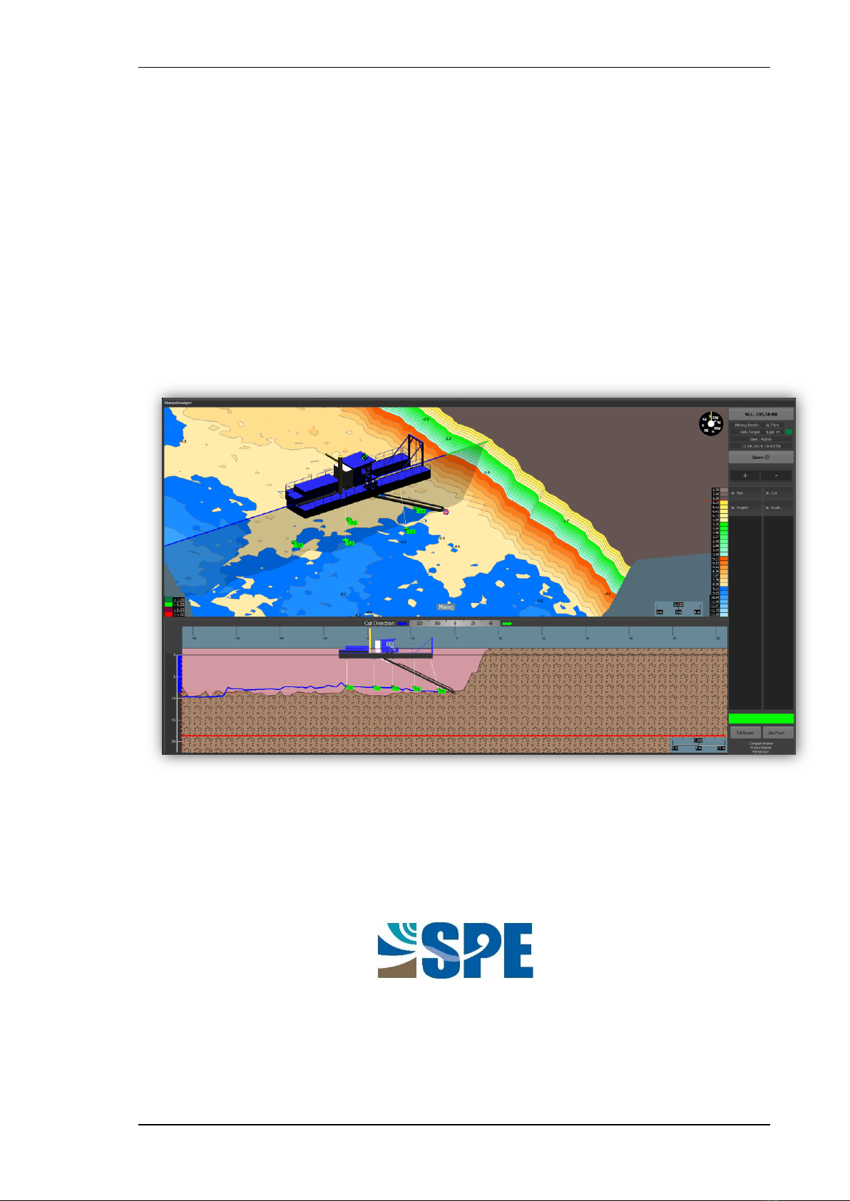
The upper part of the screen is called the plan view. It contains the digital terrain model
(DTM), which is created by using survey data, approval limits and a digital dredger model.
The plan view is a flexible 3D-visualisation, which allows the user to get a preferably
flexible and individual observation of the mining area. Center of this view is always the
loosening tool.
By default, the plan view starts in Terrain mode, in which the colour rendering refers to
the existing depth. In other modes certain display styles are changing. This chapter refers
to the default setting Terrain. The different views are described in the following sections
in detail.

Plan View
MARPO_Dredger instruction manual
4
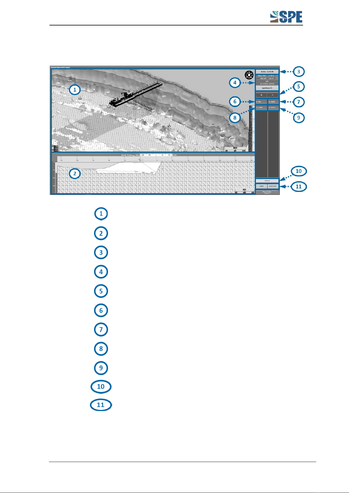
In the following figure, the main components of the plan view are marked with numbers
and listed in the table below.
Colour scale Mining depth
Page 5
Depth display Echo sounder
Page 5
Position symbols
Page 5
Data display mode
Page 5
Compass
Page 5
Colour scale Terrain model
Page 6
Scale
Page 7
Plan View
MARPO_Dredger instruction manual
5
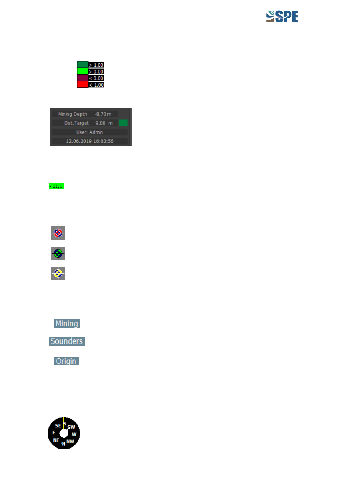
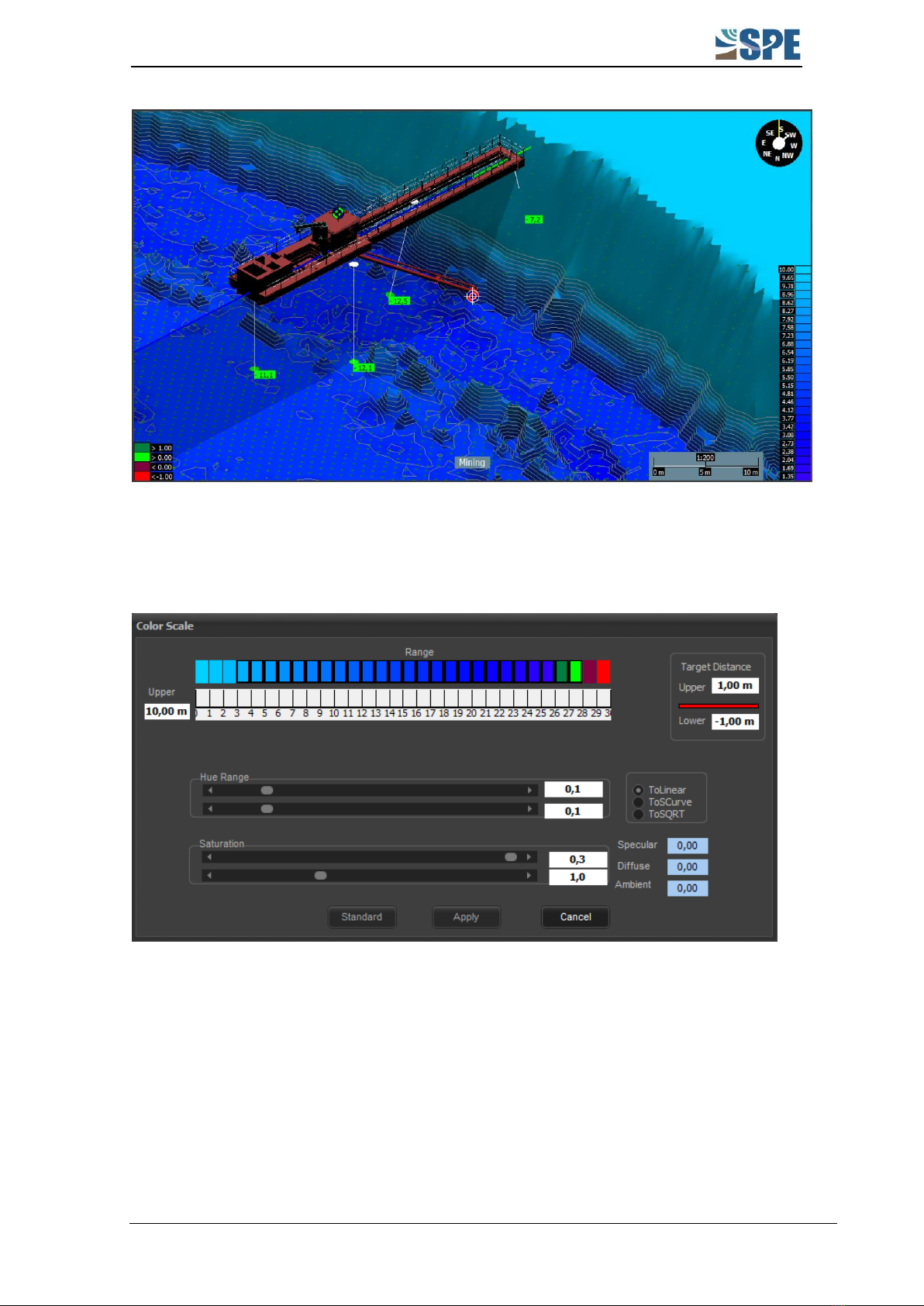
3.1 Colour scale Mining depth
The colour scale refers to the current distance in
meters to the target horizon (excavation limit). Above
the target horizon, the status is displayed in green and
below in red. The adjustment of the colours is
described in section 3.8.
The coloured field on the righthand side in the status
display shows the current status. (Dark green here, i.e.
> 1 m distance to the target horizon).
3.2 Depth display echo sounder
Measured depth of the echo sounder.
3.3 Position symbols
Position of the loosening tool (excavation point)
Position of the DGPS receiver
Position of the echo sounder scanner (if used)
3.4 Data Display Mode
The terrain model shows the mining data.
The terrain model shows the echo sounder data.
The terrain model does not show any stored data. It shows
the DTM as it was originally.
The data display mode can be changed by klicking on the respective view button several
times (see section 5.5.2).
3.5 Compass
The compass shows the direction of the map (yellow long line) and the
direction of the dredger (short white line).
Here the map is oriented to the south and the dredger to the southwest.

Plan View
MARPO_Dredger instruction manual
6
3.6 Colour scale Terrain model
The colour scale is used as a visual tool to quickly distinguish between different depth
zones.
In the Terrain view, the DTM is displayed in different colours with
reference to the height values. The red line below the value "0.00"
symbolises the water level. The depth is indicated with a negative value
downwards. The scaling can also be changed to meter NHN via Project
Settings DGM Allgemein using the button Under W.L.
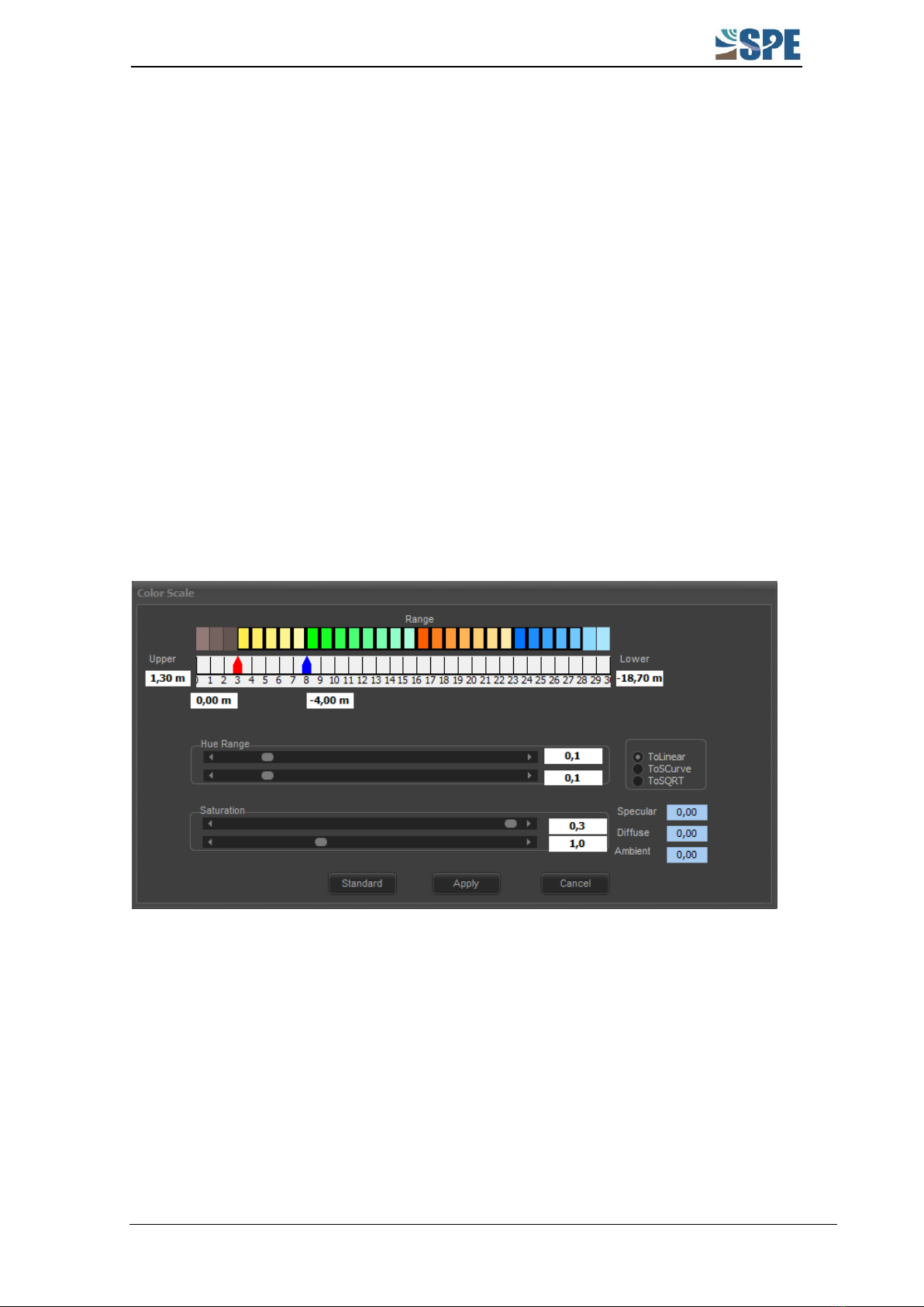
The colour scale can be individually adjusted. By clicking with the right
mouse button or tapping with the finger on the scale, the following menu
opens.
The value Upper (here: 1.30 m) is the maximum height outside the water body in
the terrain model.
Plan View
MARPO_Dredger instruction manual
7
The value Lower (here: -18.70 m) defines the lower edge of the target horizon
(mining limit) and is usually set to 2 m below the actual target horizon.
The red arrow marks the boundary between land and water. By default it is
positioned between the colours brown and yellow. The value entered below the
arrow (here: 0.00 m) is the water level and linked to the arrow accordingly.
The blue arrow and the associated value below (here: -4.00 m) can be used to
display certain depth ranges higher or lower the water level. As with the red
arrow, this arrow and value are linked. It can be visualised by pulling the red arrow
with the left mouse button to the right.
The colour can be adjusted by double left clicking on each single colour boxes. With the
left pressed mouse button, several colour boxes can be selected and then edited with the
sliders (Hue Range, Saturation). This makes individual colouring possible. The Standard
button can be used to switch back to the original state.
3.7 Scale
The scale defines the ratio of a certain distance in the terrain model on the screen to the
real distance. The scale adapts to the zoom level.
3.8 Mining Thickness mode
In this mode (see section 205.5.2), the coloured display refers to the remaining material
above the target horizon. It shows how much material is still available above the mining
limit.
Plan View
MARPO_Dredger instruction manual
8
In addition to the colour scale and the colours themselves, there is another menu option
to be changed. The colour scale of the mining depth (see section 3.1) can be adjusted by
double left clicking onto the colour scale of the Button Mining Thickness.
The four colour boxes at the right end of the colour scale represent the colour scale of the
mining depth. The target distance with the values upper and lower is corresponding.
These indicate the distance to the target horizon from which the corresponding colour is
taken.
Plan View
MARPO_Dredger instruction manual
9
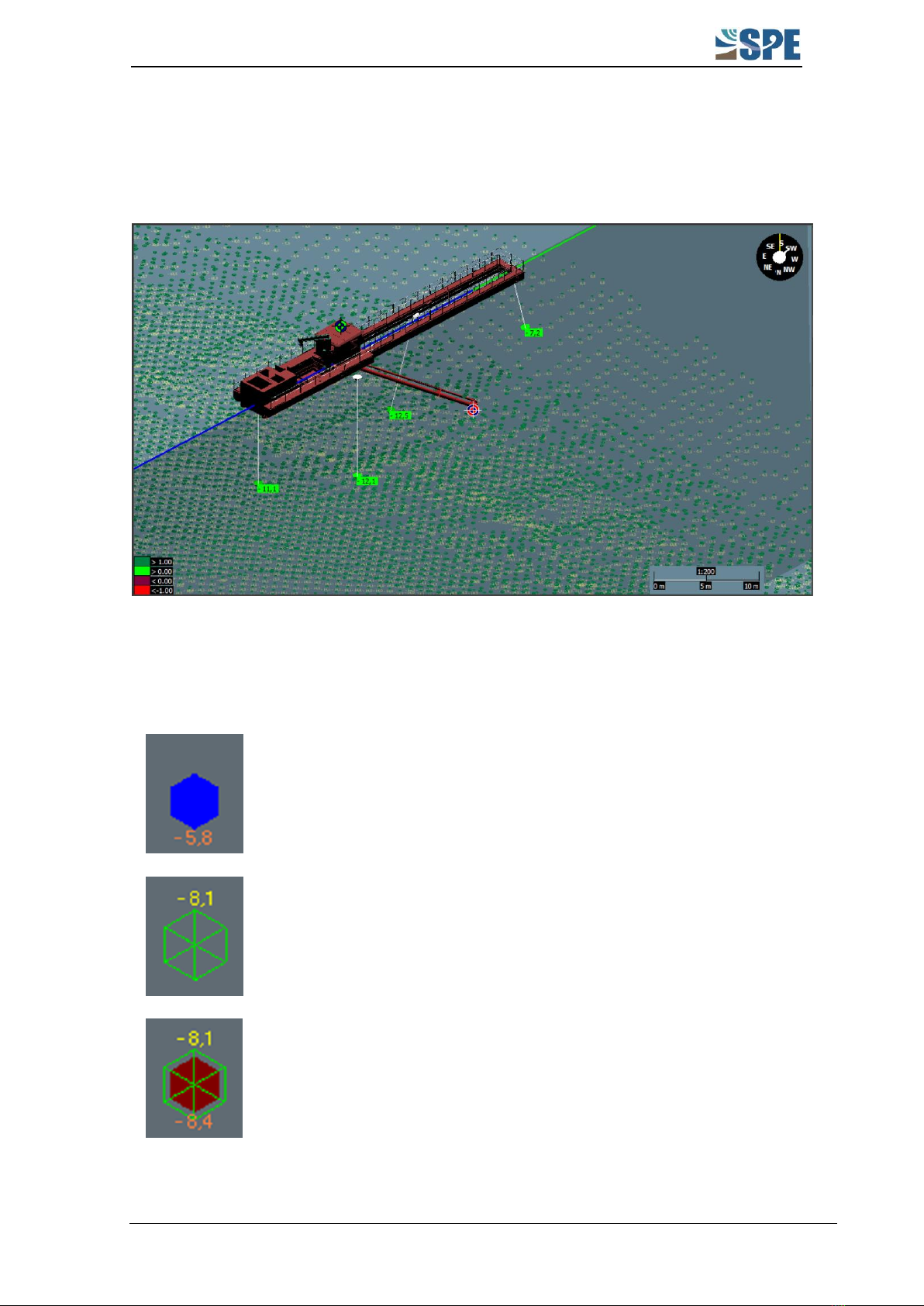
3.9 Grid Coordinate Mode
This mode hides the surface of the DTM and displays the grid points only. Therefore a
colour scale is not available here.
Grid points are created as soon as depth values are recorded by the loosening tool or the
echo sounders. The raster resolution of MARPO_Dredger 9 is 1 m x 1 m. A grid point thus
covers an area of 1 m².
Grid point for maximum depth reached by the loosening tool.
Grid point for measured echo sounder depth.
Combined view, if there are measured values at a grid point for both
the loosening tool and echo sounder.
The colours here refer to the Colour scale Mining depth.

Plan View
MARPO_Dredger instruction manual
10
3.10 Box Cut mode (optional)
The Box Cut mode is similar to the Mining Thickness mode. In this mode, however, the
coloured reference is not used to indicate the material left above the target horizon/
mining limit (red line), but to an intersecting or overlying stepped slope (green line). This
green line is part of the DTM and only available if the "Box Cut" mining concept has been
integrated into the DTM.

Plan View
MARPO_Dredger instruction manual
12
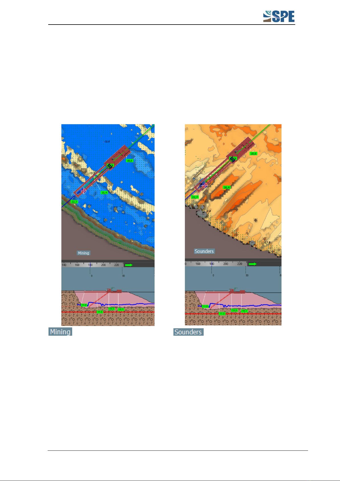
3.11 Data display mode: mining, sounder data, origin
The coloured area of the plan view in the display Terrain (section 3) and Mining Thickness
(see section 3.8) can be related to the depths of the Mining data, the Sounders data or
the Originating DTM (initial DTM, which is defined in the program for this project, without
taking into account mining or sonar data). The respective modes can be toggled by
pressing the Terrain or Mining Thickness buttons several times.
The coloured area in the plan
view refers to the depths of the mining
data.
The coloured area in the plan
view refers to the depth of the sounder
data.

Profile View
MARPO_Dredger instruction manual
13
4PROFILE VIEW
The lower view in MARPO_Dredger is called the Profile View. It is a two-dimensional view
in which the cut is placed directly through the loosening tool.
Depth scale
Page 14
Auxiliary line of the loosening tool
depth
Page
14Fehler!
Textmarke
nicht
definiert.
Orientation arrows
Page 15
Box Cut Line (optional)
Page 15
Target horizon
Page 15

Profile View
MARPO_Dredger instruction manual
14
4.1 Depth scale
The depth scale is a scale for orientation in depth.
(Unit of measurement: Meter)
The water level is the zero here.
4.2 Auxiliary line loosening tool depth
The auxiliary line is used for better
detection of the current depth of the
loosening tool. In addition, the reached
depth is coloured blue in the depth scale
on the lefthand side.

Profile View
MARPO_Dredger instruction manual
15
4.3 Orientation arrows
The orientation arrows are used for orientation in the direction of the profile cut (see
section 5.6). The blue-green line in the upper image (plan view) equals the orientation
arrows in the lower image (profile view). The line does not only show the orientation of
the profile cut, but also mirrors exactly the width of the lower view. This means that,
depending on the resolution selected in the profile view, the length of the line changes in
the plan view.
4.4 Box Cut Line (optional)
This line is displayed in green and visualises the stepped mining target. It is permanently
integrated in the DTM and cannot be changed in MARPO_Dredger. Further information:
chapter 3.10 on page 10.
4.5 Target horizon
The target horizon is the given mining limit and is displayed as a red line in the profile
view. It is integrated in the DTM. If a depth limitation module is installed in the dredge
control system, MARPO_Dredger can automatically prevent mining deeper than the
mining limit. If the loosening tool is moved to the depth of the target horizon, the depth
limitation module prevents the loosening tool from being lowered any further.
4.6 Sounder line
The depths values recorded by the sounder are displayed in the plan view by the coloured
areas (see section 3.11). In the profile view, these data are displayed as a blue line.
Menu bar
MARPO_Dredger instruction manual
16
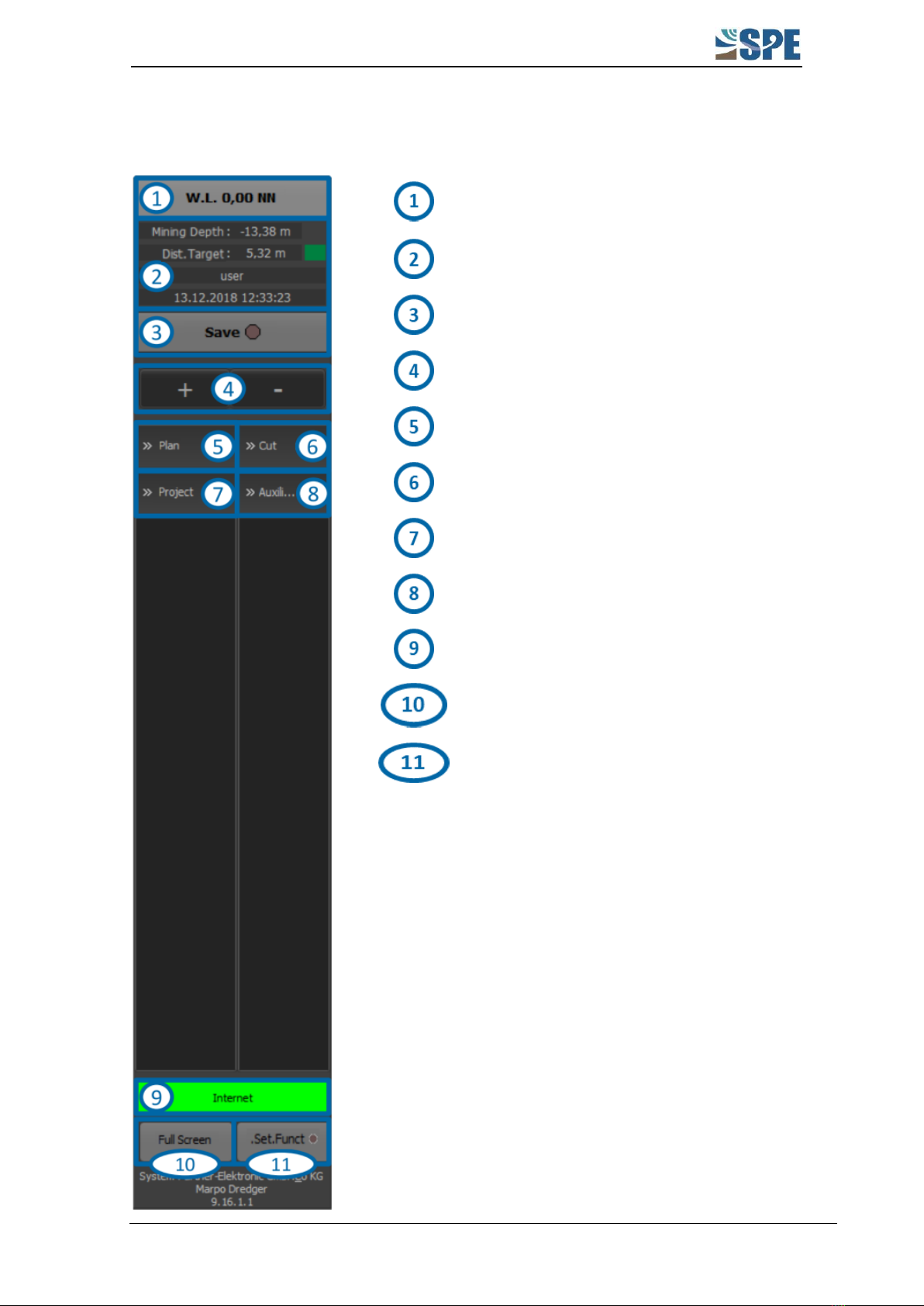
5MENU BAR
Water level display
Page 17
Status display
Page 17
Save mode
Page 18
Zoom function
Page 18
Menu for plan view
Page 19
Menu for profile view
Page 21
Project menu
Page 25
Auxiliary menu
Page 31
Status bar
Page 34
Full screen mode
Page 34
Additional features
Page 34
Table of contents
Other SPE Construction Equipment manuals


Popular Construction Equipment manuals by other brands


ELEM Technic
ELEM Technic DPP2200 user manual

Altrad
Altrad BELLE BGP 27 Poker Operator's manual

Graco
Graco EC140 Instructions for installing

probst
probst STS-EASY operating instructions

WAGNER
WAGNER Plast Coat 830 operating manual

PV-ezRack
PV-ezRack ComT 2.0: 5 Code-Compliant Planning and Installation Guide


