OPERATION
6.1 Turn on the power switch
6.2 Select the air speed:High[H]、Low[L]
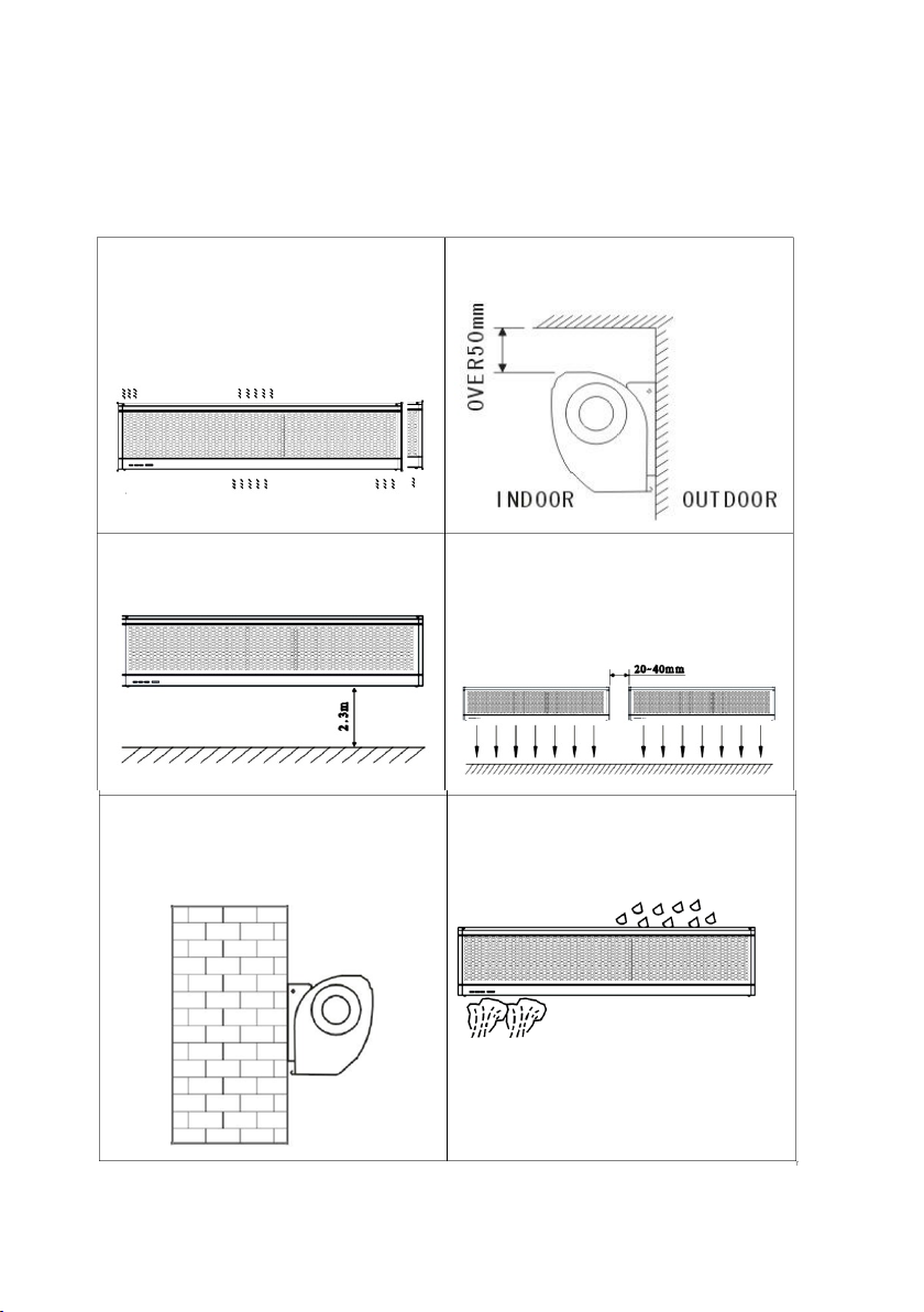
6.3 According to the installation place to adjust the wind direction parts to obtain the
best effect.
CAUTIONS
a) Use the unit at the rated voltage and frequency indicated on the nameplate.
b) Disconnect power source before unit servicing.
c) Routine maintenance must be done every year.
d) Never use petrol, benzene, thinners or any other such chemical for cleaning the unit.
e) Don’t allow water or any liquid to enter the motor.
f) When power supply comes from a socket, the plug must be in accordance with
IEC335-1. When the power cord is connected directly ,all polarity switches that the
contract gap is 3mm at least must installed in the charging line.
g) In order to avoid injure, must changed the line of air curtain by professional worker or
factory when the line happened trouble.
DECLARATION OF CONFORMITY
(€ Manufacturer
:
Inta
x
Trading SR
L
, Str.
L
ibert
ăț
ii A1-A3,
140017,Ale
x
andria, Teleorman, Romania.
These products is confor
m to the following European Directives:
LVD directive 2014/35/EU
EMC Directive 2004/108/EC am mended by DIrective 93/68/EEC
Standards (Linea 100)
EN 60335-2-80:2003+A1:2004+A2:2009
EN60335-1:2012+A11:2014, EN 62233:2008
EN 55014-1:2006 +A1:2009+A2:2011, EN 55014-2:1997+A1:2011+A2:2008,
EN61000-3-2:200 6+A1:2009+A2:2009, EN 6100-3-3:2013
Standards (Linea HEAT 100T, Linea HEAT 150T)
EN 60335-2-30:2009+A11:2012
EN 60335-2-80:2003+A1:2004+A2:2009
EN60335-1:2012+A11:2014, EN 62233:2008
EN 55014-1:2006+A1:2009+A2:2011, EN 55014-2:1997+A1:2001+A2:2 008, EN
61000-3-2:2014, EN61000-3-3:2013, EN 61000-3-12:20
11, EN 61000-3-11:2000
LINEA HEAT 100T/150T EN