Jandy RS-PS6 Installation and user guide

Installation Data
Installation Manual
AquaLink RS
PDA- Pool Digital
Assistant
WARNING
FOR YOUR SAFETY - This product must be installed and serviced by a professionalpool/spa service
technician. The procedures in this manualmust be followed exactly. Failure to followwarning notices
and instructions may result in property damage, serious injury, or death.
Pool/Spa Combination Systems and
Pool Only/Spa Only Systems
(Models PS4, PS6, PS8, P4, and P8)
H0572200-
ATTENTION
This device complies with part 15 of the FCC Rules. Operation is subject to the following twoconditions: (1) This
device may not cause harmful interference, and(2) this device mustaccept any interference received, including
interference that may cause undesired operation.
NOTE: This equipment has been tested and found to comply with the limits for a Class B digital device, pursuant to
part15 of the FCC Rules. These limits are designed to provide reasonable protection against harmful interference in
a residential installation. This equipment generates, uses and can radiate radio frequency energy and, if not installed
and used in accordance with the instructions, may cause harmful interference toradio communications. However,
there is no guarantee that interference will not occurin a particular installation. If this equipment does cause
harmful interference to radio or television reception, which can be determined by turning the equipment off and on,
the user is encouragedto try to correct the interference by one or more of the following measures:
Reorientor relocate the receiving antenna.
Increase the separation betweenthe equipment and receiver.
Connect the equipment to an electrical source on a circuit different from that to which the receiver is connected.
Consult the dealeror an experienced radio/TVtechnician for help
Modi cations made to this equipment, which are not authorized by the manufacturer, may void the user!s authority
to operate this equipment.


Page 3
Table of Contents
Section 1. Important Safety Instructions...........4
Section 2. System Overview.............................6
2.1 Package Contents.............................6
2.2 System Component Speci cations
and Dimensions................................7
2.3 Basic Plumbing................................8
Section 3. Installation........................................10
3.1 Power CenterMounting...................10
3.2 High Voltage Wiring........................10
3.3 Low Voltage Wiring.........................14
3.4 Heater Connection...........................15
3.5 Temperature Sensors........................18
3.6 Jandy ValveActuators......................18
3.7 PDATransceiver J-box Installation.18
Section 4. System Startup..................................20
4.1 Handheld Remote Programming......20
4.2.Restartingthe System
(Clear Memory) Menu.....................23
4.3 PDASystem Defaults and
General Modes.................................23
4.4 PDAHandheld Remote Menu
Flow Chart.......................................25
Section 5. Troubleshooting................................26
5.1 PDAQuick Troubleshooting Guide.26
Section 6. Power Center WiringDiagram.........28
Section 7. Power Center PCB DIPSwitch
Settings.............................................29
7.1 DIPSwitch Functions......................29
7.2 DIPSwitch Settings for Pool and
Spa Combination..............................30
7.3 DIPSwitch Settings for Pool or
Spa Only...........................................31
Section 8. General, Water Feature and
LightAux Labels..............................32
DATE OF INSTALLATION
INSTALLER INFORMATION
INITIALPRESSURE GAUGE READING (WITH CLEAN FILTER)
PUMPMODEL HORSEPOWER
FILTER MODEL SERIALNUMBER
PDAMODELSERIALNUMBER
NOTES:
EQUIPMENT INFORMATION RECORD

Page 4
Section 1. Important Safety Instructions
READ AND FOLLOW ALLINSTRUCTIONS
Lire la notice technique.
All electrical work must be performed by a licensed electrician and conform to all national, state, and
local codes. When installing and using this electrical equipment, basic safety precautions should always be
followed, including the following:
WARNING
Prolonged immersion in hot water may induce hyperthermia.Hyperthermia occurs when the internaltemperature
ofthe body reaches a level several degrees above the normal body temperature of98.6 F.The symptoms of
hyperthermia include dizziness, fainting, drowsiness, lethargy, and an increase in the internaltemperature of the
body.The effects ofhyperthermia include: 1) unawareness of impending danger; 2) failure to perceive heat; 3)
failure to recognize the need to exit spa; 4) physical inability to exit spa; 5) fetal damage in pregnant women;6)
unconsciousness resulting in a danger of drowning.
DANGER
Toreduce the risk of injury,do not remove the suction fittings of your spa or hot tub. Never operate a spa or hot
tub if the suction fittings are broken or missing. Never replace a suction fitting with one rated less than the flow rate
marked on the equipmentassembly.
WARNING
ToReduce the Risk of Injury -
a)The water in a spa should never exceed 104 F (40 C). Water temperatures between 100 F(38 C) and
104 F (40 C) are considered safe for a healthy adult. Lower water temperatures are recommended for young
children and when spa use exceeds 10 minutes.
b) Since excessive water temperatures have a high potential for causing fetaldamage during the early months of
pregnancy, pregnant or possibly pregnant women should limit spa water temperatures to 100 F (38 C).
c) Before entering a spa or hottub, the user should measure the water temperature with an accurate
thermometer since the tolerance of water temperature-regulating devices varies.
d) The use of alcohol, drugs, or medication before or during spa or hot tub use may lead to unconsciousness with
the possibility of drowning.
e) Obese persons and persons with a history of heart disease, low or high blood pressure, circulatory system
problems, or diabetes should consult a physician before using a spa.
f) Persons using medication should consult a physician before using a spa or hot tub since some medication
may induce drowsines while other medication may affect heart rate,blood pressure, and circulation.
WARNING
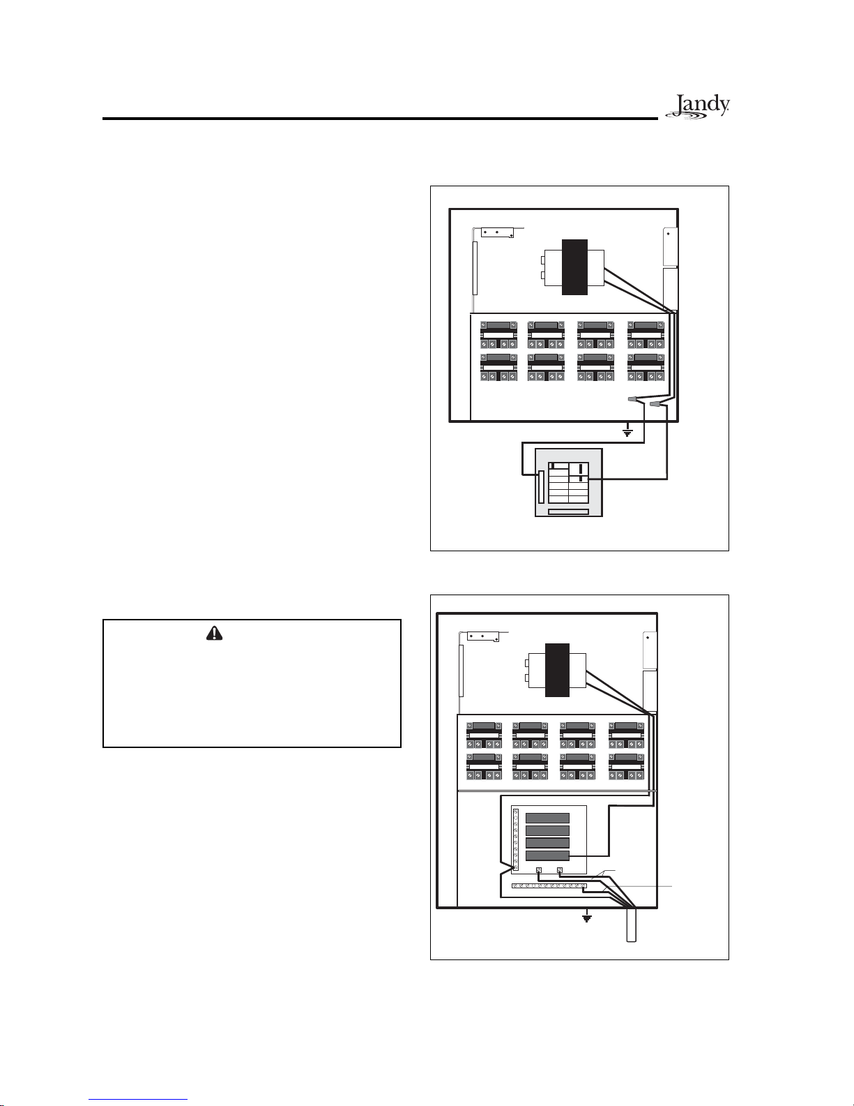
Risk of electric shock - Install the power center at least five (5) feet (152.4cm) from the inside wall of the pool
and/or hot tub using non-metallic plumbing. Canadian installations mustbe at least three (3) meters from the
water.
Children should not use spas or hot tubs withoutadult supervision.
Do not use spas or hot tubs unless all suction guards are installed to prevent body and hair entrapment.
People using medications and/or having an adverse medical history should consult a physician before using a spa
or hot tub.
AVERTISSEMENT
Danger d'electrocution - Les installations Canadiennes doivent se trouver àau moins trois (3) mètres de l%eau.
Ne pas laisser les enfants utiliser une cuve de relaxation sans surveillance.
Pour éviter que les cheveux ou une partie du corps puissent être aspirés, ne pasutiliser une cuve de relaxation si
les grilles de prise d'aspiration ne sontpastoutes en place.
Les personnesqui prennent des médicaments ou ont des problèmesde santédevraient consulter un médecin
avant d%utiliser une cuve de relaxation.

Page 5
CAUTION
Aground-fault circuit-interrupter must be provided if this device is used to control underwater lighting fixtures. The
conductors on the load side of the ground-faultcircuit-interrupter shall not occupy conduit, boxes, or enclosures
containing other conductorsunless the additional conductors are also protected by a ground-fault circuit-
interrupter. Refer to local codes for complete details.
CAUTION
Aterminal bar marked "GROUND" is provided within the power center.Toreduce the risk of electrical shock,
connect this terminal bar to the grounding terminal of your electricservice or supply panel with a continuous
copper conductor having green insulation and one that isequivalent in size to the circuitconductors supplying this
equipment, but no smaller than no.12 AWG(3.3mm). In addition, a second wire connector should be bonded with
ano. 8AWG (4.115mm) copper wire to any metalladders,water pipes, or other metal within five (5) feet (1.52m)
ofthe tub.
SAVE THESE INSTRUCTIONS
WARNING
People with infectiousdiseases should not use a spa or hot tub.
Toavoid injury, exercise care when entering or exiting the spa or hot tub.
Do not use drugs or alcohol before or during the use of a spa or hot tub to avoid unconsciousness and possible
drowning.
Pregnant or possibly pregnant women should consulta physician before using a spa or hot tub.
Water temperature in excess of 100 F/38 C may be injurious to your health.
Before entering a spa or hot tub measure the water temperature with an accurate thermometer.
Do not use a spa or hot tub immediately following strenuous exercise.
Prolonged immersion in a spa or hot tub may be injurious to your health.
Do not permit any electric appliance (such asa light, telephone, radio,or television) within 5 feet (1.5 m) of a spa
or hot tub.
The use of alcohol, drugs or medication can greatly increase the risk of fatal hyperthermia in hottubs and spas.
Water temperature in excess of 100 F/38 C may be hazardousto your health.
AVERTISSEMENT
Les personnesatteintes de maladies infectieuses ne devraient pas utiliser une cuve de relaxation.
Pour éviter des blessures, user de prudence en entrant dans une cuve de relaxation et en sortant.
Pour éviter l%évanouissement et la noyade éventuelle, ne prendre ni drougue ni alcool avant d%utiliser une cuve de
relaxation ni quand on s%ytrouve.
Les femmes enceintes, que leur grossesse soit con rmée ou non, devraient consulter un médecin avantd%utiliser
une cuve de relaxation.
Il peut être dangereux pour la santéde se plonger dans de l%eau àplusde 38 C/100 F.
Avant d%utiliser une cuve de relaxation mesurer la témperature de l%eau àl%aide d%un thermomètre précis.
Ne pas utiliser une cuve de relaxation immédiatementaprès un exercice fatigant.
L%utilisation prolongéed%une cuve de relaxation peut être dangereuse pur la santé.
Ne pas placer d'appareil électrique (luminaire, téléphone,radio, téléviseur, etc) àmoins de 1.5m de cette cuve de
relaxation.
La consommation d%alcoolou de drogue augmente considérablement les risques d%hyperthermie mortelle dans
une cuve de relaxation.
Il peut etrêdangereux pour la santéde se plonger dans de l%eau àplusde 38 C/100 F.
Attention installer: Install to provide drainage of compartment for electrical components.
WARNING
Toavoid injury ensure that you use thiscontrol system to control only packaged pool/spa heaterswhich have built-
in operating and high limit controlsto limit water temperature for pool/spa applications. This device should not be
relied upon as a safety limit control.

Page 6
Section 2. System Overview
2.1 Package Contents
All JandyAquaLink RS Systems come complete with the appropriate number of 3HPrelays needed.
Pool Digital Assistant (PDA) System Sub-Assembly
Power Centers (Sold Separately)
Standard Power Center
(with mounting brackets) Sub-Panel Power Center
(with mounting brackets and circuit
breaker mounting plate)
Two (2) JVAs
(With Pool/Spa Combination Only)
PDAHandheld RemoteOutdoor Transceiver J-boxPower Center PCB
Two (2) Temp Sensors,
AdditionalRelays (Model Dependent)

Page 7
2.2 System Component Speci cations and Dimensions
Table 1
Specifications (USAand Canada)
Power Supply 120 VAC; 60 Hz;3 A
Contact Rating (Relays) High voltage - 25 A; 3HP @ 240 VAC
1½HP @120 VAC
1500 Watts Incandescent
Low Voltage - Class Two, 1A @ 24 VAC
Service Switch All Circuits (located at Power Center in Service Mode)
Dimensions
Standard Power Center
5" 14½"
13¾"
Sub-Panel Power Center
20"
14½"
5"
NoteBreakers for Sub-Panel Power Center
only.
PDAHandheldRemote
Front View
3½"
6¾"
ïî
-»´»½¬
¾¿½µ
ÐÜß
7/8"
Side View
J-Box Transceiver
11/16"
Side View (atAngle)
4"
6"
1"
7"
Front View

Page 8
2.3 Basic Plumbing
2.3.1 Plumbing forPool and Spa Combination
The following plumbing diagrams illustrate
simplified versions of standard plumbing setups
for a pool and spa that share the same filter pump,
filter, and heater. The intake and return JVA s turn
simultaneously so when the Spa mode is selected
on theAquaLink RS PDA, water circulation
switches between pool and spa (consult the Jandy
Valve Actuator Installation and Operation Manual
to ensure that the JVA s are synchronized and rotate
properly). Please consult the Jandy Valve Plumbing
Manual for further examples of pool/spa plumbing.
Heater
Filter
Filter
Pump
Pool Drain
Spa Drain
Spa ReturnPool Return
Check
Valve
Spa
Make-up
Check
Valve
Heat Pump
SkimmersSkimmers
From Solar ToSolar
Please note that if you have a pool only or a spa
only, the diagram does not apply.
NOTE When the filter system is shared (a Pool/Spa
Combo), the spa water mustbe able to overflow
into the pool.

Page 9
2.3.2 BoosterPump Pool CleanerPlumbing
Heater
Filter
Filter
Pump
Pool IntakeSpa Intake
Spa ReturnPool Return
Check
Valve
Spa Make-up
Booster
Pump
Filter
Filter
Pump
Pool IntakeSpa Intake
Spa ReturnPool Return
Check
Valve
Spa Make-up
Energy
Filter
Cleaner
Line
2.3.3 Non-BoosterPump Pool CleanerPlumbing
Heater

Page 10
3.1 PowerCenterMounting
1. The Power Center should be located at or
near the equipment pad. Locate the Power
Center at least ve (5) feet or more away
from pool/spa and ve (5) feet off the
ground.All national, state, and local codes
are applicable.
2. Use the mounting brackets and instructions
provided with the Standard Power Center
and/or Sub-Panel Power Center.
3. Sub-Panel Power Centers have special
code requirements. Be sure to follow all
applicable local and state codes to insure
safe installation.
NOTE The Power Center is not to be considered
as suitable for use as Service Equipment.
Therefore, itis required to have the appropriate
meansof disconnection, circuit isolation, and/or
branch circuit protection installed upstream of
the Power Center.
3.2 High Voltage Wiring
3.2.1 System Power
Figure 2. Sub-Panel Power Center
Ú·´¬»®Ð«³°Î»´¿§ ß«¨òíλ´¿§
Transformer
Earth Ground
Black
White
Primary
Low voltage raceway, do not run high voltage in this compartment
From Main
Power
Ground
White
White Black
Black
Ú·´¬»®Ð«³°Î»´¿§ ß«¨òíλ´¿§
Ù®±«²¼
Ò»«¬®¿´
Transformer
Earth Ground
Breaker Panel
To 120 VAC
Breaker
Neutral
Black
White
Wire nut to
120 VAC power
Low voltage raceway, do not run high voltage in this compartment
Primary
Figure 1. Standard Power Center
Section 3. Installation
WARNING
Potentiallyhigh voltages in the AquaLinkRS
PowerCenter can create dangerous electrical
hazards, possibly causing death, serious injury
orproperty damage. Turn off power at the main
circuit of the AquaLink RS Power Center to
disconnect the Power Center fromthe system.
Depending on the amount of equipment being
controlled, run ½" or larger conduit from the
power supply panel to the bottom of the Power
Center. If you are using the Sub-Panel Power
Center, wire power to the appropriate breakers.
Pull in appropriate wire for equipment. Each piece
of equipment requires its own high voltage relay.
Connect 120 volts to the Power Center terminals.
Connect equipment ground(s). See Figures 1 and 2.

Page 11
3.2.3 Bonding the PowerCenter
Install a bonding lug to the Power Center
enclosure. Connect the bond lug, using a #8 solid
copper core wire, to an approved earth ground (an
approved ground stake, grid, or conducting metal
water pipe buried to a sufficient depth). See
Figure 3.
3.2.2 3HP (Standard) Relays
For each piece of 240 volt equipment to be
controlled, connect line power to the two (2) line
terminals and connect equipment power to the two
(2) load terminals on the same relay.
For each piece of 120 volt equipment, connect
power to a line terminal and connect equipment to
a load terminal on the same relay.
NOTE The following are the contact ratings for 3HP
(Standard) Relay. DONOTexceed any ratings.
3HP@ 240 VAC; 1½HP @ 120 VAC; 25
Amps; 1500 Watts.
Figure 3. Standard Power Center - Bonding
Ú·´¬»®Ð«³°Î»´¿§ ß«¨òíλ´¿§
Ô±¿¼ î
Ô·²» î
Ô±¿¼ ï
Ô·²» ï
Ù®±«²¼
Ò»«¬®¿´
Bonding Lug
Earth
Ground
Breaker
Panel
Blower
(120 VAC)
Filter Pump
(240 VAC)
Primary
24 VAC
Transformer

Page 12
3.2.4 UnderwaterLighting GFCI Wiring
Figure 4. GFCI Installation for Underwater
Lighting
GFCI
Outlet
ÑÐÌ×ÑÒßÔ
Standard Power Center
GFCI Outlet
(Optional)
ÑÐÌ×ÑÒßÔ
Sub-Panel Power Center
3.2.5 Jandy Pool and Spa Lights Wiring
The Jandy Pool and Spa Lights can be wired into
the JandyAquaLink RS control system to ensure
simplified operation of the lights, as well as a
means to synchronize the color change function.
Connect the lights to one of the auxiliary relays in
the Power Center.
NOTE It is recommended to connectone lightper
relay so each light can be controlled separately.
However,up to four lights can be connected on
asingle relay. If there are more than four lights
installed on one AquaLink RS system, ensure
there is more than one auxiliary relay available
in the Power Center.
Refer to Figures 5 and 6 to connect the Jandy Pool
and Spa Lights to the Power Center.
NOTE The Jandy Pool and Spa Lights are available
in 120-volt and 12-volt versions. Ifinstalling a
12-voltlight,a 120-volt/12-volt step-down (AC)
transformer, listed/certified for the application
must be used. For more information about 12-
voltinstallations, refer to the Jandy Digital,Color
Changing,Underwater Pool and Spa Lights
Installation and Operation Manual.
CAUTION
AGroundFaultCircuit Interrupter(GFCI)mustbe
provided in high voltage pool/spa lights. Do not
use aGFCI circuit breaker.The conductors on
the load side of the GFCI circuit shall not occupy
conduit, boxes, or enclosures containing other
conductors unless the other conductors are also
on the load side of a GFCI. Referto local codes
for complete details.
1. For a Standard Power Center, install an
appropriately rated GFCI receptacle next to
the breaker panel. For a Sub-Panel Power
Center install an appropriately rated GFCI
receptacle in the Power Center (use the
knockout provided on the right side of the
Sub-Panel Power Center). See Figure 4.
2. Connect neutral and hot wire (fromcircuit
breaker) to the LINE side of the GFCI.
3. Connect neutral (white wire) and the hot
(black wire) fromthe light to the LOAD
side of the GFCI.
4. Connect ground fromthe light to the
grounding bar inside the Power Center.

Page 13
ÙÚÝ× Þ´¿½µ
ɸ·¬»
Ù®»»²
ïîðÊ
Ö¿²¼§
Ô·¹¸¬
Ù®±«²¼
Ù®±«²¼
Ò»«¬®¿´
ïîð ÊßÝ
б©»® Í«°°´§
Figure 5. 120-Volt Jandy Pooland Spa Light Wiring Diagram
Figure 6. 12-Volt Jandy Pool and Spa Light Wiring Diagram
ÙÚÝ×
Ù®±«²¼
Ù®±«²¼
Ò»«¬®¿´ Þ´¿½µ
ɸ·¬»
Ù®»»²
ïîÊ
Ö¿²¼§
Ô·¹¸¬
Þ´¿½µ
ɸ·¬»
Ù®»»²
ïîðÊñïîÊ
Ì®¿²-º±®³»®
ïîð ÊßÝ
б©»® Í«°°´§

Page 14
Figure 8. PDAJ-Box Cable Connection to Power
Center PCB
Conduit Knockout forLow Voltage
PDAJ-box Wire
Heyco Fittings for
Low Voltage JVA
and SensorWires
Low Voltage
Raceway
High Voltage
Knockouts for
Conduit
(DO NOTrun any Low
Voltage wires through
these knockouts)
3.3 Low Voltage Wiring
3.3.1 Bezel Connection
Plug the 24 VAC power plug from the transformer
into its 3-pin terminal on the back of the Power
Center PCB (see Figure 7). Mount the Bezel to the
Power Center using the screws provided. Ensure
that battery wires are kept from being pinched or
damaged.
CAUTION
DO NOT INSTALLBATTERY until readyto
power up system.
3.3.2 PDAJ-Box Cable Connection to Power
CenterPCB
Make provision for the cable to be run between the
PDAJ-box and the Power Center. Never run high
voltage and low voltage in the same conduit. Pull
cable through the knockout with the Heyco fitting
and into the low voltage compartment. Strip back
jacket 6". Strip each wire a ¼" and connect to the
red, 4-pin connector on the Power Center PCB.A
multiplex kit may be required if there are more than
two cables running to a red, 4-pin connector (see
Figure 8).
NOTE For detailed tranceiver installation, see
Section 3.7.1.
Figure 7. Power Center PCB (back view)
24 VAC Power Plug
Connection

Page 15
3.4 HeaterConnection
The heater connection section applies to all
heaters or heat pumps with thermostatic circuitry
of 24 VAC or less (see pages 15 thru 17 for brand
specific installation).
NOTE If you are connecting a heater with thermostatic
circuitry of 120 VAC or greater,do not connect
to the green,10-pin Terminal Bar.Instead
connect the heater to a high voltage relay in
the Power Center and plug the spare relay into
the Electric Heater relay socket located on the
upper right hand corner of the Power Center
PCB.
3.4.1 Jandy Brand HeaterConnections
1. Connect two #14 gauge wires, designed for
use in hot environments, to the #1 and #2
terminals on the green, 10-pin Terminal Bar.
2. Connect the other ends of the #14 gauge
wires from Step 1 to the Fireman's Switch
terminal bar in place of the factory installed
wire loop.
3. Do not disconnect high limit or pressure
switches.
4. Turn the heater thermostat(s) to maximum
setting.
5. Turn the heater switch to the ON position.
For dual thermostat heaters turn switch to
Spa position.
Figure 9. Lite2 Heater Connection
Power Center PCB/Bezel
Heater
Wiring
#14
Gauge
Wire
Green 10-pin
Terminal Bar
Heater
Thermostat To
Max.
HeaterToggle
Switch To On
Terminal 1
Terminal 2 HeaterFireman's Switch
Connection
Factory
Installed
Wire Loop
3.4.2 Guidelines forSophisticated Diagnostic
Communication to LX Heaters
1. Remove the LX GUI from the heater.
2. Con rm the LX andAquaLink RS software
revisions are compatible (see table).
3. Run a 4-conductor cable from the LX GUI
red, 4-pin connector to the RS power Center
red, 4-pin connector (see Figure 10).
LX Software RevisionAquaLink RS Software
Revision
C04 to C08Hor HH
C10, C11or laterI, JJ, K or later
NOTE If connecting more than two (2) items to the RS
Power Center red, 4-pin connector, a Multiplex
PCB is required.
ÑÐÌ×ÑÒßÔ
ìíîï
ìíîï
ÎÛÜ
ÞÔÕ
ÇÛÔ
ÙÎÒ
ÎÛÜ
ÞÔÕ
ÇÛÔ
ÙÎÒ
4-Conductor
Wire
LX GUI
RS Power
Center
Figure 10. LX Heater Connection to Power Center
PDA
J-box

Page 16
3.4.3 Guidelines forHayward Heaters
1. Remove heater service door.
2. Remove factory-installed wire nut between
two (2) red wires labeled "CONNECTION
FOR FIELD INSTALLED CONTROL
SWITCH"(see Figure 11).
3. Wire nut two (2) heater wires from
AquaLink RS P.C. Board to the two (2) red
wires of the heater (see Figure 12).
4. Set the thermostat selector switch to
ON, HIGH, or SPA, and set the heater
thermostat(s) to maximum.
3.4.4 Guidelines forPentairHeaters
1. Remove the heater service door.
2. Separate the black wires (common) from
each other (see Figure 13).
3. Connect the wires from the Power Center
PCB to the two black wires on the heater
(see Figure 14).
3.4.5 Guidelines forRaypak Heaters
For the 2-wire/1 function configuration, connect
the orange/black and black/orange wires to one
contact and the yellow/black wire to the other
contact (see Figure 15).
Limit Switch
Factory
Installed
Wire Nut
R
Limit Switch
R
V
OFFON
BL
Pressure Switch
Figure 11.Hayward Heater Wiring Before
Modi cation
Limit SwitchLimit Switch
R
R
V
OFFON
BL
Pressure Switch
Wires to
Power Center
PCB
Figure 12. Hayward Heater Wiring with
AquaLink RS
Figure 13. Pentair Heater Wiring Before
Modi cation
VIO
BLK
BLK
RED
Figure 14. Pentair Heater Wiring with AquaLink RS
Wires from
Power Center
PCB
VIO
BLK
BLK
RED
Figure 15. Raypak Heater Wiring with AquaLink RS
P7
Terminal
To
AquaLink
RS System
4. Turn the heater toggle switch on, and the
heater thermostat(s) to max.
5. When connecting anAquaLink RS to a
Pentair Heater, Pentair requires that you
install the low voltage thermostat wires in
conduit separate fromANYline voltage
wires.

Page 17
3.4.6 Guidelines fora Gas Heaterand a Jandy
AE Series Heat Pump/ChillerInstallation
NOTE The following steps provide the procedure for
installing a Jandy AE Series Heat Pump.
1. Install a xed resistor, with a value of 2.2K
Ohms, in the solar sensor terminals #3 and
#4 of the green, 10-pin terminal bar of the
AquaLink RS Power Center (see
Figure 16).
2. To run the wires from the Heat Pump,
remove the 5 screws that attach the service/
wiring cover panel to the heat pump (see
Figure 16).
NOTE One end of the wiring reserved to run into
the conduitconnection labeled )Low Voltage
Connection*, located on the lower right hand
side of the heat pump (see Figure 16).
3. Run the wires from the Heat Pump control
panel through the wiring conduit located on
the outer right hand side of the Heat Pump.
4. Connect the Heat Pump to a standard
relay, then connect the relay to the solar
pump output on the PCB. Set the time to
11:59 PM; at 12:00AM, the AquaLink
RS will auto-relabel Solar as Heat Pump.
Otherwise, theAquaLink RS will auto-
relabel Solar as Heat Pump within 24 hours.
5. The Solar Button will activate the heat
pump/chiller and the Pool and/or Spa
Heater Buttons will activate the gas heater.
In this manner the pool or spa can be heated
or chilled by the heat pump, the gas heater
or both.
NOTE To program the Heat Pump control panel, refer
to the Jandy AE Series Heat Pump Manual.
ìíîïêëìíîï
ïðçèéêëìíîï
Þ¿¬¬»®§
øçʱ´¬÷
Gas Heater
Heat Pump/Chiller#2
Service/Wiring
CoverPanel
Fireman's
Switch
From Fusible
Link
To Pressure
Switch
Port for Low
Voltage Wires
Figure 16. Heater and Heat Pump/Chiller Wiring
Standard
High
Voltage
Relay
Heat Pump/Chiller#1
Gas Heater Connections
Terminals 1 and 2
2.2K Ohms Resistor
in SolarSensor
Terminals for Heat
Pump/Chiller
Low Voltage
Wiring toLow
Voltage Port
on HeatPump
Service/Wiring
CoverPanel
Port for Low
Voltage Wires
PDA
Transceiver
J-box

Page 18
3.5 Temperature Sensors
1. Drill 3/8" hole in pipe between lter
pump and lter and install the Water
Temperature Sensor per instructions
(make certain the o-ring is in place).
2. Install AirTemperature Sensor outside the
Power Center can, not in direct sunlight and
away from motors and other heat sources.
3. Install Solar Temperature Sensor
(optional) adjacent to solar panels.
4. Run the wire to the Power Center, through
the low voltage raceway. Cut off excess
wire. Strip the wire jacket back 6", then
strip each wire ¼". Connect sensor wires to
the green, 10-pin terminal bar (see
Figure 17).
3.6 Jandy ValveActuators
NOTE Mount the JVA's according to the Jandy Valve
Actuator Installation and Operation Manual.
JVAcable is type SJW-Amarked water resistant
class 3 cable and does not require conduit.
Knockouts and Heyco fittings are provided in the
Low Voltage Raceway.
1. Route the JVAwire to the Power Center.
2. Run the wire through the low voltage
raceway and plug the JVAconnectors into
their proper sockets (see Section 6. Power
Center Wiring Diagram). Verify that the
JVAon the suction plumbing is connected
to the Intake JVASocket, and the discharge
plumbing is connected to the Return JVA
Socket.
Figure 17. Temperature Sensor Wiring for a Pool/
Spa Combination
Water
Temperature
Sensor
Freeze/Air
Temperature
Sensor
Solar
Temperature
Sensor
Green 10-Pin Terminal Bar
ïðçèéêëìíîï
NOTE Do not coilthe JVAwires inside Power Center.
Toshorten the wire,remove the JVAcover
and disconnect the wire. Shorten, strip,and
reconnect.
3. For alternate plumbing con gurations the
JVAcam settings can be adjusted as needed.
See the Jandy Valve Actuator Installation
and Operation Manual, Cam Setting Chart
for proper settings.
3.7 PDATransceiverJ-box Installation
Installation Considerations. The transceivers will
transmit through walls and around corners. Steel
framing, aluminum siding, wrought iron, cyclone
fences, leaded glass, and other 900 MHz frequency
items may inhibit/prevent communication between
theAquaLink RS PDAHandheld Remote and the
Power Center. The transceivers do not require
line of sight to communicate. To optimize
communication, install transceivers in a location
that minimizes interference.
3.7.1 Outdoor TransceiverJ-box Installation
1. Turn off all power to the Power Center.
2. Mount the Outdoor Transceiver J-box at
least 6' above the ground and at least 8'
from an air blower (see Figure 18).
NOTE To improve performance of the transceiver,
mountthe J-box more than 6' above the ground.
3. Open the door to the Power Center and
remove the dead panel.
4. Feed the four conductor wire into the Power
Center through the low voltage raceway.
5. Cut off the excess wire. Strip the jacket
back 6" and strip the individual wires
approximately ¼". Connect the four
conductor wire to the red terminal bar on
the Power Center PCB.
6. Install the dead panel to the Power Center
and restore all power.

Page 19
Óß×ÒÝÑÒÒÛÝÌÑÎ
ÎÛÍÛÌ
Üî
Üí
ÔÛßÎÒ
ÑÚÚ ÑÒ
3.7.2 PDAHandheld Remote Installation
1. Remove the Handheld Remote from the
packaging.
2. On the back of the Handheld Remote,
loosen and remove the two (2) screws that
secure the cover for the battery chamber
(see Figure 19).
3. Install two (2)AAbatteries. Ensure that the
polarity is correct.
4. Re-install the cover for the battery chamber
and secure with the two (2) screws removed
in Step 2.
3.7.3 Changing the Frequency Channel
If yourAquaLink RS PDAsystemis turning items
on or off at undesignated times, anotherAquaLink
RS PDAsystem may be in close proximity using
the same or similar frequency channel. To prevent
unwanted operation the channel for yourAquaLink
RS PDAsystem can be changed. The Power Center
Transceiver and the PDATransceiver J-box must
be set to the same RFchannel.
1. At the Transceiver J-box, remove the cover
to expose the PCB (see Figure 20).
Figure 20. PDATransceiver J-Box - Internal View
Transceiver
PCB
2. On the PDAHandheld Remote, press
and hold both the UPand DOWN arrows
simultaneously for three (3) seconds.After
3 seconds, the CHANNELSETUPscreen
appears (see Figure 21). Select a channel.
Low Voltage Raceway
Power
Center
Air
Blower
PDA
Transceiver
J-box
6'
Minimum 8'
Ground
Level
3 Yellow
1 Red
2 Black
4 Green
Red 4-Pin
Terminal Bar
Figure 18. Outdoor Transceiver J-box Installation
Figure 19. Battery Installation on Handheld Remote
ËÓóíñÎêñßß
ËÓóíñÎêñßß
ÞßÌÌÛÎÇ
ïòëʨî
íðíîìðï
ÓÑÜÛÔÒÑèîêë
ÚÝÝ×ÜæÍèÚèîêÈ
כּ¼æíÊÜÝ
PDAHandheld
Remote - Back View
Two (2)
AABatteries
Battery Chamber Coverfor Battery
Chamber
Screws
Reset Switch
Learn
Switch
Green
LED
Red
LED

Page 20
Section 4. System Startup
4.1 Handheld Remote Programming
4.1.1. Basic Programming Menu
To set a particular piece of equipment to turn on
and off at predetermined times, highlight MENU
and press SELECT(see Figure 23). Highlight
PROGRAM and press SELECT. Use the UPor
DOWN buttons to highlight the equipment (for
example, Filter Pump) then press SELECT. Follow
the on-screen prompts. Use the UPor DOWN
buttons to pick each number, starting with ON
hours, press SELECTto enter and move on to the
next item to change, including picking what day(s)
the program will run. If you make a mistake, use
the BACK button to return to a number. If the
program is already entered, highlight CHANGE
PROGRAM and step through to the entry that
should be corrected.
3. Use the UPand DOWN buttons to highlight
the desired RF channel. Then press
SELECT.
4. When the RF channel is selected, the
following message appears on the PDA
display screen:
Set slide switch on J-Box PCB to the
LEARN MODE.
5. At the PCB in the Transceiver J-box, slide
the Learn Switch to LEARN (ON). See
Figure 22.
ÍÛÌÎÚÝØßÒÒÛÔ
ÎÚÝØßÒÒÛÔæï
Ë-»ßÎÎÑÉÕÛÇÍ
¬±-»¬¬¸»
ÎÚÝØßÒÒÛÔò
Ю»--ÍÛÔÛÝ̬±
½±²¬·²«»ò
ïî
-»´»½¬
¾¿½µ
ÐÜß
UP
Button
DOWN
Button
SELECTButton
Figure 21. PDAHandheld Remote Channel Setup
and Buttons
ïî
-»´»½¬
¾¿½µ
ÐÜß
Figure 23. PDAHandheld Remote Buttons
BACK
Button
UP
Button
DOWN
Button
SELECT
Button
HOT KEY1
HOT KEY2
Power ON/OFF
Button
6. On the PDAHandheld Remote display
screen, a prompt will appear with
instructions to slide the J-box Learn Switch
out of LEARN (OFF) and to press the J-box
Reset Switch.
7. At the PCB in the Transceiver J-box, slide
the Learn Switch out of LEARN and press
the Reset Switch. The Red and Green LEDs
on the J-box will blink simultaneously (see
Figure 22).
Figure 22. Tranceiver J-box PCB Learn Switch
Óß×ÒÝÑÒÒÛÝÌÑÎ
ÎÛÍÛÌ
Üî
Üí
ÔÛßÎÒ
ÑÚÚ ÑÒ
ÔÛßÎÒ
ÑÚÚ ÑÒ
Transceiver
PCB
Reset Switch
Learn
Switch
Shown
in Learn
Mode
- Switch
Position
On.
Green
LED
Red
LED
This manual suits for next models
4
Popular Home Automation manuals by other brands

Duemmegi
Duemmegi Domino DFRHT quick start guide

Bosch
Bosch Home controller AA instruction manual

LEGRAND
LEGRAND GFCI Installing and Testing

SMA Solar Technology
SMA Solar Technology SUNNY HOME MANAGER 2.0 operating manual

4-noks
4-noks Power Reducer Technical manual

HOMCOM
HOMCOM B71-056 Assembly & instruction manual