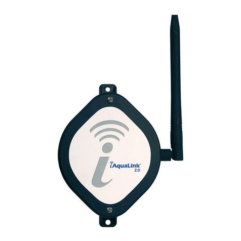
Jandy AquaLink RS Conversion Kit User manual

H0669200_REVF
FOR YOUR SAFETY - This product must be installed and serviced
by a contractor who is licensed and qualied in pool equipment by the
jurisdiction in which the product will be installed where such state or
local requirements exist, the maintainer must be a professional with
sucient experience in pool equipment installation and maintenance
so that all of the instructions in this manual can be followed exactly.
Before installing this product, read and follow all warning notices and
instructions that accompany this product. Failure to follow warning
notices and instructions may result in property damage, personal
injury, or death. Improper installation and/or operation may void the
warranty. Improper installation and/or operation can create unwanted
electrical hazard which can cause serious injury, property damage, or
death. Turn o all circuit breakers required in order to
prevent the possibility of electric shock
ATTENTION INSTALLER: This manual contains
important information about the installation, operation
and safe use of this product. This information should
be given to the owner/operator of this equipment.
WARNING
AquaLink®RS Conversion Kit
for Pentair®Enclosures
Installation Instructions

Page 2
Table of Contents
Section 1. Important Safety Instructions........ 3
Section 2. Package Contents .......................... 4
2.1 Pool Pump Suction Entrapment
Prevention Guidelines ............................ 7
2.2 Package Contents.................................. 9
Section 3. Product Compatibility....................10
Section 4. Remove the Pentair®
Control Panel .................................11
4.1 Transformer located on
low voltage side.....................................11
4.2 Transformer located on
high voltage side .................................. 14
Section 5. Install the AquaLink RS
Conversion Kit .............................. 16
5.1 Apply the New Wiring Label ................. 16
5.2 New Transformer Installation ............... 17
5.3 Install Conversion Kit.............................18
5.4 Connect Sensor Wires ......................... 19
5.5 Connecting Heater to Low
Voltage Wiring ...................................... 19
5.6 Connecting Auxilliary Equipment
to PCB.................................................. 20
5.7 Finalize Hardware Installation .............. 20
5.8 Test the Equipment .............................. 21
Section 6. Program DIP Switch Settings ...... 21
6.1 DIP Switch Functions........................... 21
6.2 DIP Switch Settings ............................. 23
6.3 DIP Switch Settings for
Solar/Heat Pump.................................. 24
Section 7. Install and Program the iQ20....... 25
Jandy®AquaLink®RS Conversion Kit

Page 2 Page 3
Section 1. Important Safety Instructions
READ AND FOLLOW ALL INSTRUCTIONS
All electrical work must be performed by a licensed electrician and conform to all
national, state, and local codes. When installing and using this electrical equipment,
basic safety precautions should always be followed, including the following:
WARNING
EQUIPMENT UNDER PRESSURE:
Always turn pump off prior to installation
or service. Your pump/filter system is
operated under pressure and the
pressure must be released before
you begin work. Please see your
pump/filter owner’s manual for further
instructions.
WARNING
To reduce the risk of electric shock,
fire or injury, service should only be
attempted by a qualified pool service
professional.
Risk of electric shock: Install the
power center at least five (5) feet (1.52
m) from the inside wall of the pool and/
or hot tub using non-metallic plumbing.
Canadian installations must be at least
three (3) meters from the water.
WARNING
Risk of electric shock which can
result in serious injury or loss of
life: Before attempting to install or
service, ensure that all power to the
circuit supplying power to the system is
disconnected or turned off at the circuit
breaker. All wiring must be done in
accordance with the National Electrical
Code®(NEC)®, NFPA-70®, including
those in Article 680 - Swimming Pools,
Fountains, and Similar Installations.
In Canada, the Canadian Electrical
Code (CEC), CSA C22.1, must
be followed. All applicable local
installation codes and regulations
must be followed.
ATTENTION: The power center
and the chlorine generator control
center are not to be considered as
suitable for use as service equipment.
Therefore, it is required to have the
appropriate means of disconnection,
circuit isolation, and/or branch circuit
protection installed upstream of the
power/control center
WARNING
To reduce the risk of injury do not
permit children to use this product
unless they are closely supervised at
all times.
WARNING
Risk of Accidental Drowning.
Extreme caution must be exercised
to prevent unauthorized access by
children. To avoid accidents, ensure
that children cannot use a spa or
hot tub unless they are closely
supervised at all times.
This appliance is not intended for use
by persons (including children) with
reduced physical, sensory or mental
capabilities, or lack of experience
and knowledge, unless they have
been given supervision or instruction
concerning use of the appliance by a
person responsible for their safety.
PREVENT CHILD DROWNING:
Do not let anyone, especially small
children, sit, step, lean or climb on any
equipment installed as part of your
pool’s operational system. Locate the
components of your operational system
at least 1 m (3 ft 3 in) from the pool
so children cannot use the equipment
to access the pool and be injured or
drown.
To reduce the risk of injury, do not remove
the suction fittings of your spa or hot tub.
Never operate a spa or hot tub if the
suction fittings are broken or missing.
Never replace a suction fitting with one
rated less than the flow rate marked on
the equipment assembly.
Table of Contents
Section 1. Important Safety Instructions........ 3
Section 2. Package Contents .......................... 4
2.1 Pool Pump Suction Entrapment
Prevention Guidelines ............................ 7
2.2 Package Contents.................................. 9
Section 3. Product Compatibility....................10
Section 4. Remove the Pentair®
Control Panel .................................11
4.1 Transformer located on
low voltage side.....................................11
4.2 Transformer located on
high voltage side .................................. 14
Section 5. Install the AquaLink RS
Conversion Kit .............................. 16
5.1 Apply the New Wiring Label ................. 16
5.2 New Transformer Installation ............... 17
5.3 Install Conversion Kit.............................18
5.4 Connect Sensor Wires ......................... 19
5.5 Connecting Heater to Low
Voltage Wiring ...................................... 19
5.6 Connecting Auxilliary Equipment
to PCB.................................................. 20
5.7 Finalize Hardware Installation .............. 20
5.8 Test the Equipment .............................. 21
Section 6. Program DIP Switch Settings ...... 21
6.1 DIP Switch Functions........................... 21
6.2 DIP Switch Settings ............................. 23
6.3 DIP Switch Settings for
Solar/Heat Pump.................................. 24
Section 7. Install and Program the iQ20....... 25
Installation & Operation Manual

Page 4
Section 2. Package Contents
WARNING
To avoid injury ensure that you use this
control system to control only packaged
pool/spa heaters which have built-in
operating and high limit controls to
limit water temperature for pool/spa
applications. This device should not
be relied upon as a safety limit control.
Water temperature in excess of 100°F
(38°C) may be hazardous to your
health.
WARNING
A terminal bar marked “GROUND” is
provided within the power center. To
reduce the risk of electrical shock,
connect this terminal bar to the grounding
terminal of your electric service or
supply panel with a continuous copper
conductor having green insulation
and one that is equivalent in size to
the circuit conductors supplying this
equipment, but no smaller than no. 12
AWG (3.3 mm2). In addition, a second
wire connector should be bonded with
a no. 8 AWG (8.4 mm2) copper wire to
any metal ladders, water pipes, or other
metal within five (5) feet (1.52 m) of the
pool/spa. In Canada, the bonding wire
must be minimum 6 AWG (13,3 mm2).
WARNING
A ground-fault circuit-interrupter must
be provided if this device is used to
control underwater lighting fixtures.
The conductors on the load side of the
ground-fault circuit-interrupter shall not
occupy conduit, boxes, or enclosures
containing other conductors unless
the additional conductors are also
protected by a ground-fault circuit-
interrupter. Refer to local codes for
complete details.
CAUTION:
This device is intended for
use with permanent swimming pools and
may also be used with hot tubs and spas
if so marked. Do not use with storable
pools. A permanently-installed pool is
constructed in or on the ground or in a
building such that it cannot be readily
disassembled for storage. A storable
pool is constructed so that it is capable of
being readily disassembled for storage
and reassembled to its original integrity.
When mixing acid or other chemicals
with water,
ALWAYS ADD THE ACID
OR CHEMICALS TO WATER. NEVER
ADD WATER TO THE ACID OR
CHEMICALS.
CAUTION: It is important to note that
certain materials used in and around
swimming pools and spas may not be
compatible with chemicals commonly
used to purify pool and spa water (e.g.
acids, chlorine, salt, stabilizers, etc.).
Zodiac Pool Systems LLC does not
warrant or guarantee that the chlorinated
water generated by the Jandy®Pro
Series chlorine generating device will not
damage or destroy certain types of plants,
decking, coping and other materials in
and around your pool and/or spa. Before
selecting materials to be used in and
around your pool and/or spa, please
discuss all options with your contractor to
assess the compatibility of such materials
and chemicals.
Some helpful considerations may
include:
• Choosing plants that can withstand
splash out of pool water containing
chlorine and/or salt and other water
purication chemicals.
Jandy®AquaLink®RS Conversion Kit

Page 4 Page 5
• All metal components used in and
around a pool should be of a high
grade, quality stainless steel.
• Careful selection of masonry
products. The porosity and
hardness of natural stones varies
greatly. Therefore we recommend
you consult with your builder
or stone contractor on the best
choice for stone materials around
your pool or spa.
• Sealing all masonry products.
Professionals in the stone industry
specify that even natural stone,
especially when used outdoors,
be sealed to prevent weathering,
staining, and premature
degradation. Consult with your
stone or deck contractor for the
proper sealer for the masonry
products you have selected to use
around your pool or spa.
• For optimal results, sealers should
be reapplied on a regular
basis. Reapply the protective
sealer on a schedule per the
manufacturer’s instructions.
• Use of chemicals other than
those recommended may be
hazardous. Follow the chemical
manufacturers instructions.
WARNING
Prolonged immersion in hot water may
induce hyperthermia. Hyperthermia
occurs when the internal temperature
of the body reaches a level several
degrees above the normal body
temperature of 37 °C (98.6 °F). The
symptoms of hyperthermia include
dizziness, fainting, drowsiness,
lethargy, and an increase in the internal
temperature of the body. The effects of
hyperthermia include:
• Unawareness of impending
danger
• Failure to perceive heat
• Failure to recognize the need to
exit spa
• Physical inability to exit spa
• Fetal damage in pregnant women
• Unconsciousness resulting in a
danger of drowning
To Reduce the Risk of Injury:
• The water in a spa should never
exceed 40°C (104°F). Water
temperatures between 38°C
(100°F) and 40°C (104°F) are
considered safe for a healthy adult.
Lower water temperatures are
recommended for young children
and when spa use exceeds 10
minutes.
• Since excessive water
temperatures have a high
potential for causing fetal damage
during the early months of
pregnancy, pregnant or possibly
pregnant women should limit
spa water temperatures to 38°C
(100°F).
•
Before entering a spa or hot tub,
the user should measure the water
temperature with an accurate
thermometer since the tolerance
of water temperature-regulating
devices varies.
• The use of alcohol, drugs, or
medication before or during
spa or hot tub use may lead
to unconsciousness with the
possibility of drowning.
• Obese persons and persons with
a history of heart disease, low or
high blood pressure, circulatory
system problems, or diabetes
should consult a physician before
using a spa.
• Persons using medication
should consult a physician
before using a spa or hot tub
since some medication may
induce drowsiness while other
medication may aect heart rate,
blood pressure, and circulation.
•
People with infectious diseases
should not use a spa or hot tub.
• To avoid injury, exercise care
when entering or exiting the spa
or hot tub.
Installation & Operation Manual

Page 6
•
Do not use drugs or alcohol before
or during the use of a spa or hot
tub to avoid unconsciousness and
possible drowning.
• Pregnant or possibly pregnant
women should consult a
physician before using a spa or
hot tub.
• Water temperature in excess of
38°C (100°F) may be injurious to
your health.
• Before entering a spa or hot tub
measure the water temperature
with an accurate thermometer.
• Do not use a spa or hot tub
immediately following strenuous
exercise.
• Prolonged immersion in a spa or
hot tub may be injurious to your
health.
• Do not permit any electric
appliance (such as a light,
telephone, radio, or television)
within 1.5 m (5 ft.) of
a spa or hot tub.
•
The use of alcohol, drugs or
medication can greatly increase
the risk of fatal hyperthermia in
hot tubs and spas.
WARNING
Improper gas heater installation or
maintenance can cause nausea or
asphyxiation from carbon monoxide
in ue gases which could result in
severe injury, or death. For indoor
installations, as an additional measure
of safety, Zodiac Pool Systems LLC
strongly recommends installation of
suitable Carbon Monoxide detectors in
the vicinity of this appliance and in any
adjacent occupied spaces.
WARNING
Jandy®Pro Series chlorine generating
devices are designed for domestic
(residential) swimming pool use only.
Contrary use could affect performance,
void warranty, and may result in property
damage, serious injury, or death.
• Operating a chlorine generator
without water owing through
the cell may cause a build up of
ammable gases, resulting in re
or explosion.
• Keep equipment out of reach of
children.
• A damaged supply cord
should only be replaced by the
manufacturer, service agent or
electrician.
• When installing and using this
electrical equipment, always
follow basic safety precautions.
• Before performing installation,
disconnect all power.
• Connect to a circuit that is
protected by a ground-fault circuit
interrupter (GFCI).
• Do not install within an outer
enclosure or beneath the skirt of
a hot tub or spa.
ATTENTION: This device complies
with part 15 of the FCC Rules.
Operation is subject to the following
two conditions: (1) This device may not
cause harmful interference, and (2) this
device must accept any interference
received, including interference that
may cause undesired operation. This
device must be installed to provide a
separation distance of at least 20cm
from all persons and must not be
collocated or operating in conjunction
with any other antenna or transmitter,
except in accordance with FCC multi-
transmitter product guidelines.
NOTE: This equipment has been
tested and found to comply with the
limits for a Class B digital device,
pursuant to part 15 of the FCC Rules.
These limits are designed to provide
reasonable protection against harmful
interference in a residential installation.
This equipment generates, uses and
can radiate radio frequency energy
and, if not installed and used in
accordance with the instructions, may
cause harmful interference to radio
communications.
Jandy®AquaLink®RS Conversion Kit

Page 6 Page 7
WARNING
Pump suction is hazardous and
can trap and drown or disembowel
bathers. Do not use or operate
swimming pools, spa, or hot tubs
if a suction outlet cover is missing,
broken, or loose: The following
guidelines provide information for
pump installation that minimizes the
risk of injury to users of pools, spas,
and hot tubs:
Entrapment Protection: The pump
suction system must provide
protection against the hazards of
suction entrapment.
Suction Outlet Covers: All suction
outlets must have correctly installed,
screw-fastened covers in place. All
suction outlet (drain) covers must be
maintained. Drain covers must be
listed/certified to the latest version
of ANSI®/ASME®A112.19.8 or its
successor standard, ANSI/APSP-16.
They must be replaced if cracked,
broken, or missing.
Number of Suction Outlets Per Pump:
Provide at least two (2) hydraulically-
balanced main drains, with covers,
as suction outlets for each circulating
pump suction line. The centers of the
main drains (suction outlets) on any
one (1) suction line must be at least
three (3) feet apart, center to center.
See Figure 1.
The system must be built to include
at least two (2) suction outlets (drains)
connected to the pump whenever the
pump is running. However, if two (2)
main drains run into a single suction
line, the single suction line may be
equipped with a valve that will shut
off both main drains from the pump.
The system shall be constructed such
that it shall not allow for separate or
independent shutoff or isolation of
each drain. See Figure 1.
More than one (1) pump can be
connected to a single suction line
as long as the requirements above
are met.
Must comply with the latest version
of ANSI/ASME A112.19.8 or its
successor standard, ANSI/APSP-
16, the standard for Suction Fittings
For Use in Swimming Pools, Wading
Pools, Spas, and Hot Tubs.
2.1 Pool Pump Suction Entrapment Prevention Guidelines
However, there is no guarantee
that interference will not occur
in a particular installation. If this
equipment does cause harmful
interference to radio or television
reception, which can be determined
by turning the equipment off and
on, the user is encouraged to try
to correct the interference by one
or more of the following measures:
• Reorient or relocate the receiving
antenna.
•
Increase the separation between
the equipment and receiver.
• Connect the equipment to an
electrical source on a circuit
dierent from that to which the
receiver is connected.
• Consult the dealer or an
experienced radio/TV technician
for help.
Modifications made to this equipment,
which are not authorized by the
manufacturer, may void the user’s
authority to operate this equipment.
This device contains license-exempt
transmitter(s)/receiver(s) that comply
with Innovation, Science and Economic
Development Canada's license-exempt
RSS(s) Operation is subject to the
following two conditions: (1) This device
may not cause interference. (2) This
device must accept any interference,
including interference that may cause
undesired operation of the device.
Installation & Operation Manual

Page 8
Testing and Certification: Suction
outlet covers must have been tested
by a nationally recognized testing
laboratory and found to comply with
the latest version of ANSI/ASME
A112.19.8 or its successor standard,
ANSI/APSP-16, the standard for
Suction Fittings For Use in Swimming
Pools, Wading Pools, Spas, and Hot
Tubs.
Fittings: Fittings restrict flow; for best
efficiency use fewest possible fittings
(but at least two (2) suction outlets).
Avoid fittings which could cause an
air trap.
Pool cleaner suction fittings must
conform to applicable International
Association of Plumbing and
Mechanical Officials (IAPMO®)
standards.
Listed/certified to the latest
published version of
ANSI/ASME A112.19.8 or
its successor standard,
ANSI/APSP-16.
Anti-entrapment
Cover/Grate or Suction
Fitting, securely-fastened
to Main Drain Sump
Listed/certified to the latest
published version of
ANSI®/ASME®A112.19.8 or
its successor standard,
ANSI/APSP-16.
Anti-entrapment
Cover/Grate or Suction
Fitting, securely fastened to
Main Drain Sump
At Least
3 Feet
Suction Outlet
(Main Drain)
Suction Outlet
(Main Drain)
Valves permitted only after tee Pump
No valves between
Tee and Main Drains
Skimmer
SAVE THESE INSTRUCTIONS
Aqualink RS Conversion Kit is ETL Classied to the following standards
UL 1563
CSA C22.2#218.1
Water Velocity: The maximum water
velocity through the suction fitting
or cover for any suction outlet must
be 1.5 feet per second unless the
outlet complies with the latest version
of ANSI/ASME A112.19.8 or its
successor standard, ANSI/APSP-16,
the standard for Suction Fittings For
Use in Swimming Pools, Wading
Pools, Spas, and Hot Tubs. In any
case, do not exceed the suction fitting’s
maximum designed flow rate.
If 100% of the pump’s flow comes from
the main drain system, the maximum
water velocity in the pump suction
hydraulic system must be six (6) feet
per second or less, even if one (1) main
drain (suction outlet) is completely
blocked. The flow through the
remaining main drain(s) must comply
with the latest version of ANSI/ASME
A112.19.8 or its successor standard,
ANSI/APSP-16, the standard for
Suction Fittings For Use in Swimming
Pools, Wading Pools, Spas, and Hot
Tubs.
Jandy®AquaLink®RS Conversion Kit

Page 8 Page 9
2.2 Package Contents
Before starting, check that you have the correct parts as indicated below. If any parts
are missing or incorrect, please call your local distributor or technical support at
1-800-822-7933 for
assistance.
KIT
Item Description QTY
1
AquaLink
®
RS System Level
1
2
Transformer
1
3
Transformer Bracket
1
4
PIB Bracket
1
5
System Level Board Hinge
1
6
iQ20 Web Connect Device
1
7
Low Voltage Dead Front
1
8* Enclosure Conversion Wiring Diagram Label 1
9* Professional Installation Required Label 1
*
NOT SHOWN - The AquaLink RS Conversion Kit for Pentair®enclosures
includes a wiring diagram overlay, button function/UI label and a sheet of user
interface auxiliary labels.
Table 1. Kit Contents
4
3
5
2
1
7
6
LS-A10247-PT2
LEI-X XXXX
2.0
Figure 1. Kit Contents
Installation & Operation Manual

Page 10
Section 3. Product Compatibility
Please read before proceeding.
This conversion kit can be used on most versions of the following Pentair systems.
Before beginning contact Fluidra technical support for validation on the specic
system conguration and/or systems not referenced.
AquaLink RS Conversion Kit for use with the following equipment
EasyTouch®*
EasyTouch®PL4/PLS4
IntelliTouch®**
IntelliCenter®
*All respective brands and trademarks are property of Pentair Corporation.
** Replace with Jandy One Touch interface.
It is not recommended to use this conversion kit in conjunction with Pentair integrated
Saltwater systems such as Intelichlor, or iChlor.
For congurations which have Pentair integrated Saltwater systems, replace the salt
system with Jandy AquaPure or TruClear.
Jandy®AquaLink®RS Conversion Kit

Page 10 Page 11
Section 4. Remove the Pentair®Control Panel
Before beginning the installation, verify the location has adequate WiFi coverage or
a wired Ethernet connection to the home router. The AquaLink RS Conversion Kit
uses a connection to the Internet. If Internet access is questionable or not functional,
it is advised to not proceed with the Pentair control panel removal and changes until a
access is ensured.
NOTE Use of this AquaLink®RS Conversion Kit with Pentair®
integrated Saltwater systems is not recommended. Refer to the
compatibility section 3 of this manual before proceeding.
TIP: For faster AquaLink®RS set up and programming, use tape and a marker to tag each
relay and valve connector, as you remove it, with the relay number, name, and function.
WARNING
Risk of electric shock which can result in serious injury or
death: Before attempting to install or service, ensure that all power to
the circuit supplying power to the system is disconnected or turned o
at the circuit breaker. All wiring must be done in accordance with the
National Electrical Code®(NEC)®, NFPA-7®.
In Canada, the Canadian Electrical Code (CEC), CSA C22.1, must be followed. All
applicable local installation codes and regulations must be followed.
4.1 Transformer located in control panel compartment
1. Turn o power at the breaker panel.
2. Remove 2 retaining screws on top of the High Voltage cover panel,
see Figure 2(a).
a
Figure 2. Remove Dead Front Screws
3. Remove the High Voltage cover panel from enclosure.
4. Remove power to transformer from either the relay or resettable fuses.
Installation & Operation Manual

Page 12
5. Remove the top two screws on Pentair control panel, swing panel down to
allow access to wiring behind it, see Figure 3(a).
a
Figure 3. Remove Pentair Control Panel Screws
6. Disconnect power connection from the transformer.
7. Unplug valve actuator’s, mark them intake and return.
8. Disconnect the Ethernet cable, see Figure 4(a).
9. Unplug the auxiliary relays, see Figure 4(b).
a
b
Figure 4. Unplug Auxiliary Relays
10.Unplug RS-232, including saltboard if one exists. If salt removed, replace
screws to maintain water tightness.
11. Unplug spa controller (if installed).
12.Disconnect all temperature sensors.
13.Remove 2 inner retaining screws from transformer assembly, see Figure
5(a).
Jandy®AquaLink®RS Conversion Kit

Page 12 Page 13
14.Remove 2 outer retaining screws from transformer assembly, see Figure 5(b).
b
a
Figure 5. Remove Transformer Assembly
15.Remove old transformer from enclosure.
16.Remove 2 outer retaining screws on top of the High Voltage cover panel,
see Figure 6(a).
17.Remove the High Voltage cover panel from enclosure.
18.Remove 2 inner retaining screws from Pentair®control panel,
see Figure 6(b).
b
a
Figure 6. Remove Lower Screws
19.Remove Pentair®control panel from enclosure.
20.Remove salt board if one exists.
21.Remove IntelliClor®circuit breaker.
Installation & Operation Manual

Page 14
22.Remove or bend back circuit breaker mounting tab.
4.2 Transformer located on high voltage side
1. Turn o power at the breaker panel.
2. Remove 2 retaining screws on top of the High Voltage cover panel,
see Figure 7(a).
a
Figure 7. Remove Dead Front Screws
3. Remove the High Voltage cover panel from enclosure.
4. Locate existing transformer and unplug it.
5. Remove existing transformer wires from resettable fuses, see Figure 8(a)
6. Remove existing transformer retaining screws, see Figure 8(b)
7. Remove existing transformer and replace retaining screws back into holes.
b
a
Figure 8. Remove Existing Transformer
Jandy®AquaLink®RS Conversion Kit

Page 14 Page 15
8. Remove the top two screws on Pentair control panel, swing panel down to
allow access to wiring behind it, see Figure 9(a).
a
Figure 9. Remove Pentair®Control Panel Screws
9. Disconnect power connection from the transformer.
10.Unplug Valve actuator’s, mark them intake and return.
11. Disconnect the Ethernet cable, see Figure 10(a).
12.Unplug the auxiliary relays, see Figure 10(b).
a
b
Figure 10. Unplug Auxilary Relays
13.Unplug RS-232, including saltboard if one exists.
14.Unplug spa controller (if installed).
Installation & Operation Manual

Page 16
15.Disconnect all temperature sensors.
16.Remove the 3 retaining screws from circuit breaker assembly located behind
control panel, see Figure 11(a).
a
Figure 11. Remove Circuit Breaker Assembly
Section 5. Install the AquaLink®RS
Conversion Kit
5.1 Apply the New Wiring Label
1. Place AquaLink RS Conversion wiring diagram label over existing Pentair®
wiring diagram on the inside of the enclosure door. DO NOT COVER
EXISTING PENTAIR WARNINGS OR RATING INFORMATION,
see Figure 12(a).
a
Figure 12. Warning Label
Jandy®AquaLink®RS Conversion Kit

Page 16 Page 17
5.2 New Transformer Installation
CAUTION: The Jandy Aqualink transformer must be wired to 120V.
1. Use new transformer bracket to install new transformer in the control panel
compartment, see Figure 13(a). Ensure all screw holes and openings not
being used are properly closed o and sealed.
2. Wire new transformer to 120 VAC. If applicable, use supply previously
connected to the Pentair®transformer.
3. Connect 120 VAC to the transformer. Line (black), Neutral (white), and
ground (green).
4. Connect transformer output terminal to PCB board 24VAC input terminal.
a
Figure 13 New Transformer Mounting
Installation & Operation Manual

Page 18
5.3 Install Conversion Kit
CAUTION If wiring is close to the top of metal enclosure, route
the wiring, use wraps or ties, and add electrical insulating tape
to ensure no contact is possible between wiring and metal
enclosure.
1. Secure AquaLink®RS Conversion Kit hinge using the 2 retaining screws
removed in section 2.4, see Figure 14(a)
2. Slide 3 tabs on AquaLink RS Conversion Kit PIB into the slots in bracket, see
Figure 14(b).
3. Secure AquaLink RS Conversion Kit PIB onto bracket with 2 top screws.
4. Slide pins on AquaLink RS Conversion Kit into hinge, see Figure 14(c).
c
aaa
aa
b
aa
b
aa
b
Figure 14. AquaLink®RS Conversion Kit Hinge
5. Plug in all Valve actuator's, Auxiliary, and RS-485 to the AquaLink RS
Conversion Kit panel.
NOTE If a Jandy saltwater chlorinator is being installed, refer to that
manual for instructions.
Jandy®AquaLink®RS Conversion Kit

Page 18 Page 19
5.4 Connect Sensor Wires
Connect the following sensors:
• Water Temperature
• Air Temperature
• Solar Temperature (optional)
1. Reconnect the water, air, and optional solar sensors to the green terminal
bar on the RS board, see Figure 15.
Figure 15. Connect Sensors to Green Terminal Bar
NOTE If a solar system is installed, the Freeze/Air Sensor will
become the Solar Sensor. A special Freeze Sensor Kit (Part
#6996) is needed. Follow instructions included with the Kit.
5.5 Connecting Heater to Low Voltage Wiring
NOTE Millivolt, electronic ignition, or heat pump with thermostatic
circuitry of 24 VAC or less.
Installation & Operation Manual

Page 20
1. If connecting a Low Voltage pool heater (for example, a Jandy®brand heater),
connect two (2) 14 gauge wires, designed for use in hot environments, to
the proper terminals on the 10 pin terminal bar (see Figure 4). If you are
connecting a High Voltage pool heater, contact Zodiac for instructions.
2. Bring the two (2) heater wires from the PCB over to the heater and wire nut in
series with heater circuitry as if you were wiring a reman’s switch or a heater
delay.
3. Turn the heater thermostat to the Spa position and maximum setting.
4. Turn the heater toggle switch on.
5. Do not disconnect the high limit or pressure switches.
NOTE For Spa Heater, make connection to the Spa heater Interface
Board and plug it into the Spa Heater socket.
5.6 Connecting Auxiliary Equipment to PCB
Connect the high voltage relay plugs into their appropriate sockets according
to the wiring diagram located on the inside of the Power Center door.
NOTE This appliance has up to 9 supply connections.
NOTE Pool filter pump socket is on the far left of the PCB and the spa
filter pump relay socket is on the right after AUX 6 socket.
5.7 Finalize Hardware Installation
1. Install retaining screw on top left of AquaLink RS Conversion Kit chassis, see
Figure 16(a).
a
Figure 16 AquaLink RS Conversion Kit Mounting
Jandy®AquaLink®RS Conversion Kit
Table of contents
Other Jandy Network Hardware manuals