Janome JP-104 User manual

JANOME ELECTRO PRESS
JP-104 JP-204 JP-504 JP-1004
JP-1504 JP-3004 JP-5004
JPH-104 JPH-204 JPH-504 JPH-1004
JPH-1504 JPH-3004 JPH-5004
JPU-104 JPU-204 JPU-504 JPU-1004
JPU-1504 JPU-3004 JPU-5004 JPU-8004
Operation Manual
<Maintenance>
“For Qualified Maintenance Persons ONLY”
Thank you for purchasing the Electro Press.
*Read this manual thoroughly in order to properly use this machine.
Be sure to read “For Your Safety”before you use the machine. It will
protect you from possible danger during operation.
*After having read this manual, keep it in a handy place so that you or
the operator can refer to it whenever necessary.

Maintenance Electro Press JP Series 4
i
FOR YOUR SAFETY
Safety Precautions
The precautions stated in this manual are provided for the customerto make the best use of this
product safely, and toprovide preventive measures against injuryto the customer or damage to
property.
・・・・・Be sure to follow the instructions・・・・・
Various symbols are used in this manual. Please read the following explanations to understand what
each symbol stands for.
●Symbols indicating the Degree of Damage or Danger
The following symbols indicate the degree of damage or danger which may be incurred if these
notes are not heeded.
●Symbols indicating the type of Danger and Preventive Measures
The following symbols indicate the type of safetymeasure that should be taken.
Warnings
Cautions
These “Cautions”indicate the possibility
of accidental injury or
damage to property.
These “Warnings”indicate the possibility of death or serious injury.
Indicates prohibition.
Donot touch. (contact prohibition)
Never do this. (general prohibition)
Besure to unplug the power supplyfrom wall outlet.
Do not disassemble, modify or repair.
Be sure to follow instructions.
Besure to check grounding.
Indicates necessity
Indicates the type of safety measure that should be taken.
Take care. (General caution)

Maintenance Electro Press JP Series 4
ii
FOR YOUR SAFETY
Warnings
Regularly replace the built-
in battery (optional) in the body or control
box. It is preferable to replace it every 3 years.
Failure to do so may cause malfunction or defect.
Keep the emergency stop switch within reach of the operator while
teaching and while running the machine.
It is dangerous if the machine cannot be stopped quickly and safely.
Regularly check that the I/O-S circuits and
emergencystop switch work
properly.
This is necessary so that the machine can be stopped quickly and safely
in
order to avoid danger.
Do not leave the unit plug
ged in (power cord and connectors) when it is not in
use for long periods of time. Dust can cause fire.
Be sure to shut off the power supply before removing the power cord.
Check regularly that the mounting screws are always firmly
tightened.
Loose screws may cause injury or damage.
Power the unit only with the rated voltage.
Excessive voltage can cause fire or malfunction of the unit.
Do not sprinkle water or oil on the unit, control box, or its cable.
Contact with water can causeelectric shock, fire, or malfunction of theunit.
IPProtection Rating is IP40.
Aperson entering the machine’s operation area may be injured.
Put up a “No Entry”or “No Operating”warning sign in a clearly visible
position near the machine.

Maintenance Electro Press JP Series 4
iii
FOR YOUR SAFETY
INSTALLATION
Warnings
Install an interlock as a safeguard that triggers an emergency stop
when it is activated using the I/O-S connector included in the package.
Use protective wear (helmet, protective gloves, protective glasses and
protective footwear) when installing the machine.
Place the machine on a suitable flat surface that can support its weight
and do not cover the cooling fan venton the top of the stand-alone and head
type models.
An insufficientor unstable area can cause the machine to fall, overturn,
breakdown or overheat.
Place the machine in a well-ventilated area for the health and safety of
the operator.
<Example>

Maintenance Electro Press JP Series 4
iv
FOR YOUR SAFETY
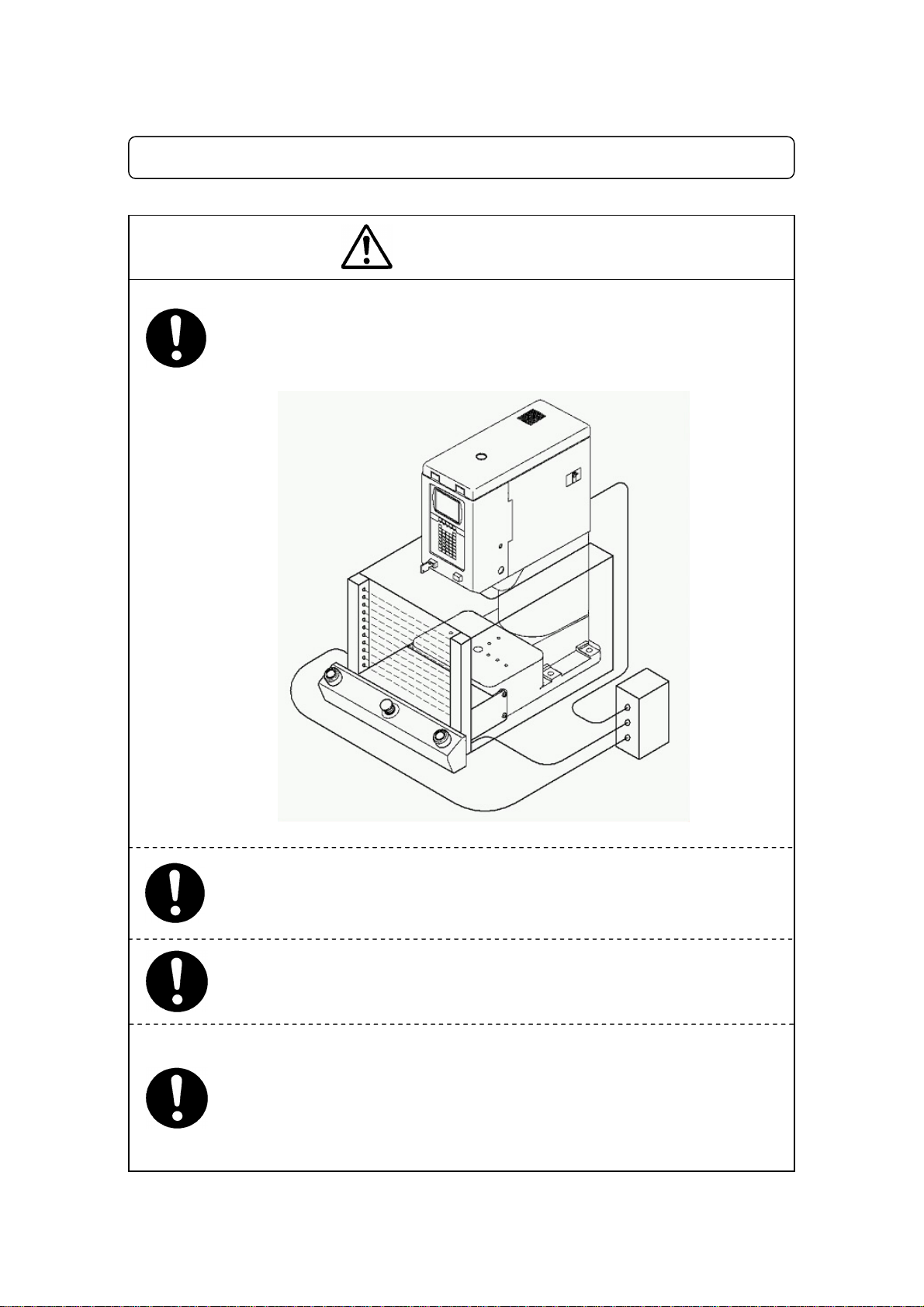
Confirm that the unit is properly grounded.
Apower supply earth should be connected complying with Type Dgrounding
.
(under 100 Ωof resistance.)
Insufficient grounding can cause electric shock, fire or malfunction.
Do not attempt to disassemble or modifythe machine.
Disassembly or modification may cause electric shock, fire or malfunction.
Do not use the unit near inflammable or corrosive gas.
If leaked gas accumulates around the unit, itcan cause fire.
IPProtection Rating is IP40.
Plug the power cord into the wall outlet firmly.
Incomplete insertion into the wall outlet heats the plug and can cause fire.
Check that the plug is not covered with dust.
Be sure to shut off the power supply before connecting the power cord.
Be sure to usewithin the voltage range indicated on the unit.
Failure to do so may cause electric shock orfire.
Turn off the unit before inserting and removing cables.
Failure to do so may result in electric shock, fire, or malfunction of the unit.
IPProtection Rating is “IP40.”
Warnings
Use the machine in an environment between 0 to 40 degrees
centigrade with a humidity of 20 to 95 percent without condensation.
Use outside these conditions may result in malfunction.
IPProtection Rating is “IP40.”
Keep the emergency stop switch within reach of the operator while
teaching and running the machine.
It is dangerous if the machine cannot be stopped quickly and safely.

Maintenance Electro Press JP Series 4
v
FOR YOUR SAFETY
Warnings
Use the machine in an environment where no electric noise is
present.
Attach an eyebolt and use a crane
or other equipment to transport the
machine.
Failure to do so may result in malfunction or defect.
Use the machine in an environment where it is not exposed to
direct sunlight.
Direct sunlight may cause malfunction or defect.
Be sure to confirm that jigs such as the electric screwdriver unit, etc.
are properly connected.
Failure to do so may result in injuryor defect.
Be sure to check the wiring to the main unit.
Improper wiring may cause malfunction or defect.
Be sure to shut off the power supply before plugging in
the power
cord.
Do not bump or jar the machine while it is being transported or
installed.
This can cause defects.
Place the control box on a flat surface more than 80 cm above the floor so
that it is easier to operate it.
Use the machine in an environment that is not dusty or damp.
Dust and dampness may cause failure or malfunction.
The installation mount should be steel. For the stand-
alone type, it
should be able to support the machine’
s weight. For the head and unit
types, it needs to support the machine’s weight and pressing capacity.

Maintenance Electro Press JP Series 4
vi
FOR YOUR SAFETY
WORKING ENVIRONMENT
Warnings
When you lubricate or inspect the unit, unplug the power cord from
the outlet.
Failure to do so may result in electric shock or injury.
Be sure to shut off the power supply before removing the power cord.
During operation, always have the emergency stop switch within the
operator’s reach.
For the operator’s safety, the emergency stop switch is necessary to make a
quick and safe stop in an emergency.
Always be aware of the machine’s movement, even in the teaching mode.
Special attention will protect the operator from injury.

Maintenance Electro Press JP Series 4
vii
FOR YOUR SAFETY
DURING OPERATION
Warnings
When starting the machine, check that no object will interfere with the
machine’s operation.
Under no circumstances should you go inside the working area or
place your hands or head inside the working area while the machine is
operating.
During teaching, tests, and actual operation, always have the
Emergencystop switch within the operator’s reach.
For the operator’s safety, the emergency stop switch is necessary to
make a quick and safe stop in an emergency.
If anything unusual (e.g. a burning smell) occurs, stop operation and
unplug the cable immediately. Contact your dealer or the office listed
on the last page of this manual.
Continuous use without repair can cause electric shock, fire, or breakdown
of the unit.

Maintenance Electro Press JP Series 4
viii
PREFACE
The operation manual for the JANOME Electro Press consists of the following parts. “For Your
Safety”is also provided so that the customer can make the best use of this product safely. This
section includes preventive measures that can be taken against injury to the customer or damage
to property. Please be sure to read “For Your Safety”before using this product.
Setup This explains how to set up the Electro Press.
* For those who have received training in Electro Press safety and
installation.
Maintenance This explains Electro Press maintenance.
* For those who have received training in Electro Press safety and
installation.
Teaching and
Operation Lists part names and data structure and provides the basic knowledge
necessary to operate the Electro Press.
Operation This explains how to operate the Electro Press.
Specifications This provides comprehensive specifications, including mechanical and
electrical requirements.
Note: The product specifications in these manuals may differ from those of the machine you have
received due to product upgrades.
Please be sure to follow the instructions described in these manuals. Proper use of the robot
will ensure continued functionality and high performance.
These manuals are based on the standard application. Menu items may vary depending on the
model.
BE SURE TO MAKE A PROPER GROUNDING WHEN YOU INSTALL THE
MACHINE.
Be sure to save data whenever it is added or modified. Otherwise,
changes will not be saved if the power to the robot is cut off.
Be sure to shut off the power supply before plugging in the power cord.

Maintenance Electro Press JP Series 4
ix
CONTENTS
FOR YOUR SAFETY___________________________________________________________ i
PREFACE _________________________________________________________________ viii
CONTENTS_________________________________________________________________ ix
1. CHECKING BEFORE ACTIVATION _____________________________________________1
2. TEACHING DATA SAVE/BACKUP ______________________________________________2
3. MAINTENANCE_____________________________________________________________4
3-1 Greasing _______________________________________________________________4
3-2 Full Inspection ___________________________________________________________4
4.ADJUSTMENT______________________________________________________________5
4-1 Adjustable Value List ______________________________________________________5
4-2 Load Calibration__________________________________________________________7
4-2-1 Load Calibration Amount Offset (Zero Reset) Function_________________________8
4-2-2 Load Calibration Function ______________________________________________10
4-2-3 Load Calibration Function (Number)______________________________________10
4-2-4 Load Calibration Function ______________________________________________12
4-3 Absolute Position Adjustment_______________________________________________16
5. HOW TO INSTALL PRESS SYSTEM SOFTWARE_________________________________21
6. TROUBLE SHOOTING ______________________________________________________22
6-1 Self-Diagnosis __________________________________________________________22
6-2 Error Number List________________________________________________________23
6-3 Failure Diagnosis________________________________________________________24
6-3-1 Diagnostic Mode _____________________________________________________26

Maintenance Electro Press JP Series 4
1
1. CHECKING BEFORE ACTIVATION
Check the following items before you register data or operate the machine.
■ Obstacles
Check that there are no obstacles in or around the Electro Press working area.
■ Emergency Stop Function
Check that the I/O-S circuit (Interlock) and emergency stop switch work properly.
Without checking this you may not be able to stop the machine quickly and safely.
The Electro Press will stop running if the interlock comes ON or you press the emergency stop
switch.
<How to release the emergency stop switch>
Turn the pressed in emergency stop switch in a clockwise direction to release the emergency
stop.

Maintenance Electro Press JP Series 4
2
2. TEACHING DATA SAVE/BACKUP
[Save]
All teaching data is temporarily saved in the Electro Press. However, if the power to the Electro
Press is turned OFF, it will disappear. Be sure to save teaching data whenever it is added or
modified.
●Press the “SAVE”key.
Be sure to save data whenever it is added or modified.
Otherwise, changes will not be saved if the power to the
robot is cut off.
Caution
Do not turn the power to the Electro Press OFF during the
save operation.
If the machine stops while saving data due to emergency
stop, the save operation will be canceled. To re-
save the
data, release
the emergency stop, return the ram to the
mechanical
home position so that the LCD displays the base
screen and press the SAVE key.
Caution

Maintenance Electro Press JP Series 4
3
[Back Up]
Back up data in case of accident.
To create backup data, start up the program “JP Designer Limited Edition”included in the
Operation Manual CD-ROM. Retrieve data from the machine and save the retrieved data in a
file.
The teaching data is sent from machine to PC as a unit. You cannot send a single program on
it’s own.
The machine has a data storage area and a work area. When you start up the machine, the
teaching data in the storage area will be copied to the work area. The copied data is used for
running and teaching. The data in the work area will be deleted when the power to the machine
is turned OFF.
When data is retrieved from the machine it comes from the work area. When data is sent to the
machine from the PC, it is saved in the storage area automatically.
If you are using “JP Designer”, the same operation can also be executed by selecting
[Receive Data] from the [Communication] pull-down menu.
<Electro Press> <PC>
Data
Receive/Send
Work areaStorage area
Backup Data

Maintenance Electro Press JP Series 4
4
3. MAINTENANCE
3-1 Greasing
To grease the ram, remove the M6 screw (illustrated below) to allow old grease to come out and
inject the new grease into the grease nipple on the ram slider.
The models JP-3004, JP-5004, JPH-3004 and JPH-5004 have maintenance covers. On
these models, the M6 Screw and Grease Nipple are inside the cover.
3-2 Full Inspection
It is recommended that you inspect the Electro Press every 2 years or 3 million strokes.
Janome Sewing Machine Co., Ltd. (Industrial Automation Systems Division) or your dealer can
inspect or repair it for you at cost price.
Recommended grease: Pilonock Universal #2 (Nihon Oil Co., Ltd.)
For smooth operation and long-life, grease
the ram of the Electro Press
every one million strokes (or 6 to 12 months depending on frequency
of
use.)
Be sure to turn the main power OFF before greasing.
Maintenance Cover
*
Unit Type
Grease Nipple
M6 Screw
Stand-Alone/ Head Type
Grease Nipple
*
M6 Screw
*

Maintenance Electro Press JP Series 4
5
4. ADJUSTMENT
4-1 Adjustable Value List
To confirm that values such as the calibration amount are normal, refer to the “Adjustable Value
List.”The “Adjustable Value List”may cover up to two pages depending on the setting.
Press the [ESC] key to return to the previous page.
●Press the [MODE] key to display the
Maintenance Mode Menu.
●Select “Adjustment”and press the [ENTR]
key.
●Select “Adjustable Value List”and press
the [ENTR] key.
●An “Adjustable Value List”like the one to
the right is displayed.
The Adjustable Value List may cover two
pages depending on the setting.
Use the [CURSOR] and [CURSOR] keys
to move between pages.
Position Offset 0.000 mm
Read Load #1 449 N
Load CalAmnt #1 0 N
Read Load #2 938 N
Load CalAmnt #2 487 N
Read Load #3 1427 N
Load CalAmnt #3 961 N
Pos'nAdjAmnt #1 0.000 mm
Ref Load #1 0 N
Pos'nAdjAmnt #2 0.221 mm
Ref Load #2 8000 N
Load Offset 447 N
<Adjustable Value List Screen>
Adjustment
Adjustable Value List
Position Offset
Load Calibration
Clear Load Calibration
Position Adjustment
Clear Position Adjustment
Measure of Strain
Load CalAmnt Offset
Load Calibration (Number)
Maintenance Mode Menu
Adjustment
Version Information
Setting Information
Diagnostic Mode
Mechanical Adjustment Mode

Maintenance Electro Press JP Series 4
6
Position Offset
This value is added to or subtracted from position values in a program while it is running. It is
used to absorb any deviation when the same teaching data is being run on several Electro
Presses. It does not change the teaching data itself. The offset setting affects all programs.
Read Load #1 to 7, Load CalibrationAmount #1 to 7
The Read Load amounts and Load Calibration Amounts are settings used to calibration load
amounts. Up to seven points can be set. Three points have been registered as default settings.
If these amounts are consistent with those in the “Load Calibration Values List”, then there is no
problem.
However, if there is a considerable difference between the two, it is necessary to reenter
the load calibration value.
PositionAdjustmentAmount #1 to 7, Ref Load #1 to 7
These settings are used to calibrate the strain that occurs when load is applied. Up to seven
points can be set. Two points (one is when zero load is applied and the other is when a load is
applied) have been registered as default. (These points have not been registered for the unit
type.)
If “Absolute Position Adjust Y/N (System settings)”is set to “Enable”, the strain will be calculated
from this value.
Load Offset
This value is added to or subtracted from the load values.
Without applying load, select “Load Offset”from “Adjustment”in the maintenance mode menu
( MODE key) and press the [ENTR] key to fix the default value. The offset amount is set so
that 0 is displayed when no load is applied. In this way, when power is turned on load reset is
executed manually.
This setting does not change teaching data. The offset setting effects all programs.

Maintenance Electro Press JP Series 4
7
4-2 Load Calibration
The ram on the Electro Press is equipped with a load cell, which enables high-precision load
control.
The load cell is also equipped with a zero reset function. This function resets the load to zero
when the load standard is changed.
The load cell amplifier and the calibration software can be adjusted or corrected.
Calibration of the load cell is performed in the following three steps.
Load cell amplifier output adjustment
(Calibration Software) Load calibration function
(Zero Reset) Automatic load reset function
Load calibration amount offset function
In normal operation execute a zero point adjustment using the zero reset function. There are
two types of zero reset functions: [Automatic Load Reset] function automatically conducts the
zero point adjustment for each stroke and the [Load Calibration Amount Offset] function, which is
used to conduct a zero point adjustment manually when necessary.
Load calibration is usually performed with the load calibration function.
Output adjustment of the load cell amplifier should be done during overall maintenance or when
the load offset value exceeds 25% of the standard load value. For details regarding the
adjustment, refer to the Service Manual.
The adjustment methods for the [Load Calibration] function and the [Zero Reset] function are
explained in this manual.
Please contact Janome Sewing Machine Co., Ltd. (Industrial Automation Systems Division) or
your dealer when replacing boards etc. for a load cell amplifier output adjustment..
If you cannot calibrate the load cell by yourself, Janome Sewing Machine Co., Ltd. (Industrial
Automation Systems Division) or your dealer will calibrate your load cell at cost price.

Maintenance Electro Press JP Series 4
8
4-2-1 Load Calibration Amount Offset (Zero Reset) Function
Manually offsets the load amount and the zero reset.
When you use this function, be sure not to apply any load to the ram.
●Enter teaching mode to set the Load Calibration Amount Offset.
●Press the [MENU] key.
●Selectt [System Settings] and press the
[ENTR] key.
●Select [Load Auto Reset Y/N] and press
the [ENTR] key.
●Press the [CURSOR ↓] key, select
[Disable Load Auto Reset] and press the
[ENTR] key.
Teaching Mode Menu
Program LIST
Program Copy, Delete, Move
Counter Clear
Alarm
System Settings
System Settings
COM1 Data Transmission Settings
Absolute Position Adjust Y/N
Load Auto Reset Y/N
Buttons Simultaneity
Reducing Work Time Y/N
Back Light Auto OFF
Change The Alarm Sound
Move to Work Pos. At Start Y/N
When Out Of Sensor range
Prohibit Operation at Standby
Wait after Probe Y/N
Load Auto Reset Y/N
Enable Load Auto Reset
Disable Load Auto Reset
Reset at Each Start

Maintenance Electro Press JP Series 4
9
●Press the [MODE] key, select [Adjustment]
and press the [ENTR] key.
●Select [Load CalAmnt Offset] and press
the [ENTR] key.
●The screen will display the optimum value
for the offset. Press the [ENT] key to apply
the displayed value to offset those set at
the factory.
●You can also enter a number for the
calibration amount.
Note:
When you enter a calibration amount, do not enter a number that is too large.
If the number entered is too large, it can lead to malfunction of the Electro Press.
If any malfunction occurs, contact Janome Sewing Machine Co., Ltd. (Industrial Automation
Systems Division) or your dealer.
Maintenance Mode Menu
Adjustment
Version Information
Setting Information
Diagnostic Mode
Mechanical Adjustment Mode
Adjustment
Adjustable Value List
Position Offset
Load Calibration
Clear Load Calibration
Position Adjustment
Clear Position Adjustment
Measure of Strain
Load CalAmnt Offset
Load Calibration (Number)
Enter a number.
Load CalAmnt Offset -0.5 kg

Maintenance Electro Press JP Series 4
10
4-2-2 Load Calibration Function
<Confirmation of Load CalibrationAmount>
Firstly, to confirm the Adjustable Value List is
normal, refer to [Adjustable Value List.]
Up to seven of these Read Load/ Load
Calibration Amounts can be set. Check the
amounts registered on each page. 3 Read
Load/ Load Calibration Amounts are set
before shipment. If all the amounts are in
agreement with the Adjustable Value List, no
further adjustment is necessary. Press the
[ESC] key to return to the main screen.
If there is any significant difference between the value on your screen and the adjustable
value list, reenter the load calibration from the adjustable value list. Refer to the next
page.
4-2-3 Load Calibration Function (Number)
●Enter teaching mode.
●Press the [MODE] key to bring up the Maintenance Mode Menu.
●Select [Adjustment] and press the [ENTR] key.
●Select [Load Calibration (Number)] and
press the [ENTR] key.
The screen to right will appear.
●To change the read load, enter a new
value using the numeric keys and press
the [ENTR] key.
Position Offset 0.000 mm
Read Load #1 449 N
Load CalAmnt #1 0 N
Read Load #2 938 N
Load CalAmnt #2 487 N
Read Load #3 1427 N
Load CalAmnt #3 961 N
Load Offset 447 N
Load Calibration
#1
Enter a Number.
Read Load 0N
Other manuals for JP-104
2
This manual suits for next models
21
Table of contents
Other Janome Power Tools manuals
Popular Power Tools manuals by other brands

Velleman
Velleman VTSUSB1 user manual

Bomag
Bomag BPH 80/65 Operating instructions, maintenance instructions

Rikon Power Tools
Rikon Power Tools 30-230 owner's manual

Lincoln Electric
Lincoln Electric Welding Fume Control brochure

Josef Kihlberg
Josef Kihlberg JK35-590 Repair instructions

Solid-State Laser
Solid-State Laser Spectra-Physics Opal user manual