Avdel 73200 Tool User manual

Instruction Manual
Original Instruction
73200 Tool
Hydro-Pneumatic Power Tool

2

3
Contents
Safety Instructions 4
Specification 5
Intent of Use 5
Tool Specification 5
Tool Dimensions 5
Putting into Service 6
Air Supply 6
Operating Procedure 6
Nose ssemblies 7
A delok® Nose Assembly Selection 7
Standard Nose Assembly Selection 7
Fitting Instructions 8
Servicing the Tool 10
Daily 10
Weekly 10
MolyLithium Grease EP 3753 Safety Data 10
Molykote® 55m Grease Safety Data 11
Molykote® 111 Grease Safety Data 11
Ser ice Kit 12
Maintenance 12
Dismantling Instructions 13
Assembly Instructions 14
General ssembly of Base Tool 73200-02000 15
Parts List for 73200-02000 16
Priming 17
Oil Details 17
Hyspin® VG32 Oil Safety Data 17
Priming Kit 18
Priming Ports 18
Stroke Setting 18
Initial Priming Procedure 19
Top-up Priming Procedure 20
Fault Diagnosis 21
Declaration of Conformity 22
LIMITED W RR NTY
vdel makes the limited warranty that its products will be free of defects in workmanship and materials which occur under normal
operating conditions. This Limited Warranty is contingent upon: (1) the product being installed, maintained and operated in accordance
with product literature and instructions, and (2) confirmation by vdel of such defect, upon inspection and testing. vdel makes the
foregoing limited warranty for a period of twelve (12) months following vdel’s delivery of the product to the direct purchaser from vdel.
In the event of any breach of the foregoing warranty, the sole remedy shall be to return the defective Goods for replacement or refund for
the purchase price at vdel’s option. THE FOREGOING EXPRESS LIMITED W RR NTY ND REMEDY RE EXCLUSIVE ND RE IN LIEU
OF LL OTHER W RR NTIES ND REMEDIES. NY IMPLIED W RR NTY S TO QU LITY, FITNESS FOR PURPOSE, OR
MERCH NT BILITY RE HEREBY SPECIFIC LLY DISCL IMED ND EXCLUDED BY VDEL.
vdel UK Limited policy is one of continuous product de elopment and impro ement and we reser e the right to change the specification of any product without prior notice.

4
Safety Instructions
This instruction manual must be read with particular attention to the following safety rules, by any person installing, operating or servicing
this tool.
1
Do not use outside the design intent.
2
Do not use equipment with this tool/machine other than that recommended and supplied by A del UK Limited.
3
Any modificati
on undertaken by the customer to the tool/machine, nose assemblies, accessories or any equipment supplied by
A del UK
Limited or their representati es, shall be the customer’s entire responsibility. A del UK Limited will be pleased to ad ise upon any proposed
modification.
4
The tool/machine must be maintained in a safe working condition at all times and examined at regular inter als for damage and
function by
trained competent personnel. Any dismantling procedure shall be undertaken only by personnel trained in A del UK Limited procedures.
Do not dismantle this tool/machine without prior reference to the maintenance instructions. Please contact A del UK Limited with your
training requirements.
5
The tool/machine shall at all times be operated in accorda
nce with rele ant Health and Safety legislation. In the U.K. the “Health
and
Safety
at Work Act 1974” applies. Any question regarding the correct operation of the tool/machine and operator safety should be directed to
A del UK Limited.
6
The precautions
to be obser ed when using this tool/machine must be explained by the customer to all operators.
7
Always disconnect the airline from the tool/machine inlet before attempting to adjust, fit or remo e a nose assembly.
8
Do not operate a tool/machine that
is directed towards any person(s) or the operator.
9
Always adopt a firm footing or a stable position before operating the tool/machine.
10
Ensure that ent holes do not become blocked or co ered and that hoses are always in a good condition.
11
The
opera
ting pressure shall not exceed 8.5
bar.
12
Do not operate the tool if it is not fitted with a complete nose assembly unless specifically instructed otherwise.
13
Care shall be taken to ensure that spent stems are not allowed to create a hazard.
14
The tool must be fitted with an undamaged pintail deflector before operating.
15
When the tool is fitted with a stem deflector, it should be rotated until the aperture is facing way from the operator and ot
her
person(s)
working in the icinity.
16
When using the tool, the wearing of safety glasses is required both by the operator and others in the icinity to protect aga
inst
fastener
ejection, should a fastener be placed ‘in air’.
17
Take care to a oid entanglement of loose clothes, ties, long hai
r, cleaning rags etc. in the mo ing parts of the tool which should
be kept dry
and clean for best possible grip.
18
When carrying the tool from place to place keep hands away from the trigger/le er to a oid inad ertent start up.
19
Excessi e contact wi
th hydraulic fluid oil should be a oided. To minimi
s
e the possibility of rashes, care should be taken to wash
thoroughly.
20
C.O.S.H.H. data for all hydraulic oils and lubricants is a ailable on request from your tool supplier.
21
Glo es shall be worn
at all times.
5
Specification
Intent of Use
The hydro-pneumatic 73200 is designed to place A del® lockbolt and breakstem fasteners.
For a complete tool, order a base tool part number 73200-02000 and select a nose assembly from the Nose Assemblies section on page 7 to suit
your application.
The safety instructions must be followed at all times.
Tool Specification
ir Pressure
Minimum
–
Maximum
5.
0
–
7.0
bar
(
73
–
102
lbf/in
2
)
Free ir Volume Required
@ 5.0 bar / 73
lbf/in
2
14.
2
litres
@ 7.0 bar / 102
lbf/in
2
19.9
litres
Stroke
Minimum
20
mm
(0.79 in)
Pull Force
@ 5.0 bar / 73 lbf/in
2
25.9 kN (5823 lbf)
@ 7.0 bar / 102 lbf/in
2
36.2 kN (8138 lbf)
Cycle Time
Approximately
3
s
econds
Noise Level
Less than
L
Aeq,T =
75
dB(A)
Weight
Without nose equipment
4.9
0
k
g (
10
lb
1
3
oz
)
Vibration
Less than
2.5
m/s
2
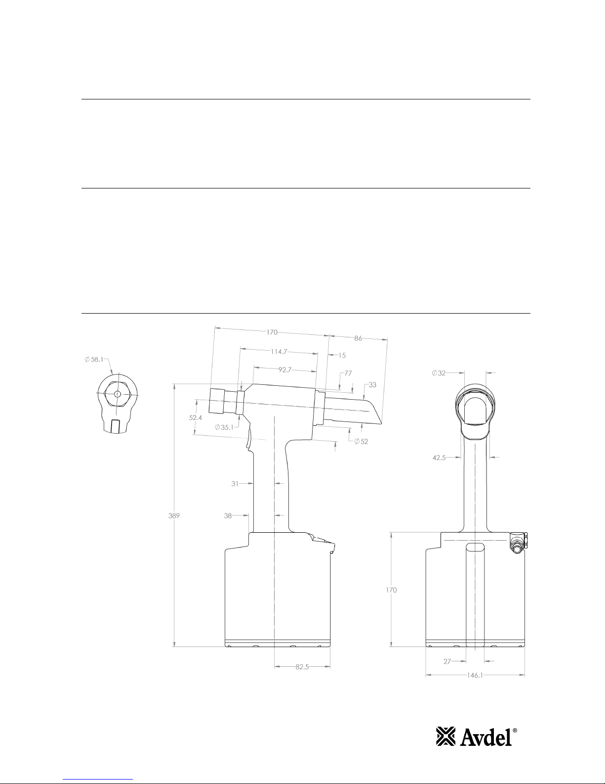
Tool Dimensions
All dimensions are shown in millimetres.

6
Putting into Service
ir Supply
All tools are operated with compressed air at an optimum pressure of 5.5 bar. We recommend the use of pressure regulators and filtering systems
on the main air supply. These should be fitted within 3 metres of the tool (see diagram below) to ensure maximum tool life and minimum tool
maintenance.
Air supply hoses should ha e a minimum effecti e working pressure rating of 150% of the maximum pressure produced in the system or 10 bar,
whiche er is the highest. Air hoses should be oil resistant, ha e an abrasion resistant exterior and should be armoured where
operating conditions may result in hoses being damaged. All air hoses MUST ha e a minimum bore diameter of 6.4 millimetres or ¼ inch.
Operating Procedure
I M P O R T N T
Do not attempt to break off a pintail without the installation of a collar. This will cause the unsecured portion of the pintail to eject from the
nose at a high speed and force.
When installing lockbolt products:
-
•Ensure that the correct nose assembly is fitted.
•Connect the tool to the air supply.
•Push the A delok® pin through the application hole.
•Place the collar on the pin (orientate as shown).
•Keeping the head of the pin against the application, push the tool on to
the protruding pin tail.
•Fully depress the trigger. One cycle will ensure that the collar is swaged
into the lock groo es of the pin and that the pin breaks at the breaker
groo e.
•Release the trigger. The tool completes its cycle by pushing itself off the
collar and ejecting the pin tail at the rear.
When installing breakstem products:-
•Ensure that the correct nose assembly is fitted.
•Connect the tool to the air supply.
•Insert the fastener stem into the nose of the tool.
•Bring the tool with the fastener to the application to the application so that the protruding fastener enters squarely into the hole of the
application.
•Fully depress the trigger. The tool cycle will broach the fastener.
•Release the trigger. The tool completes its cycle.

7
Nose ssemblies
vdelok® Nose ssembly Selection
A delok® nose equipment is a ailable in four types. It is essential that the correct nose assembly is fitted prior to operating the tool.
VDELOK® NOSE SSEMBLY SELECTION
Ø
NOSE EQUIPMENT
DESCRIPTION
B
C
D
P RT NO.
mm
inch
mm
inch
mm
inch
mm
inch
3/16"
Vertical Flats
21
0.812
16
0.625
54
2.120
25
1.000
07200
-
02500 *
3/16"
Horizontal Flats
21
0.812
16
0.625
54
2.120
25
1.000
07200
-
02700 *
1/4"
Vertical Flats
21
0.812
16
0.625
54
2.120
25
1.000
07200
-
02600 *
1/4"
Horizontal Flats
21
0.812
16
0.625
54
2.120
25
1.000
07200
-
02800 *
1/4"
Horizontal Flats (Stepped)
21
0.812
16
0.625
54
2.120
25
1.000
07
200
-
03300 *
1/4"
Round
21
0.812
-
-
54
2.120
-
-
07200
-
03500 *
5/16"
Horizontal Flats
27
1.060
23.6
0.930
91
3.580
40
1.580
07220
-
02700
5/16"
Horizontal Flats (Stepped)
27
1.060
23.6
0.930
94
3.700
46
1.830
07220
-
03400
5/16"
Round
27
1.060
-
-
91
3.580
-
-
07220
-
05600
3/8"
Round
27
1.060
-
-
70
2.750
-
-
07220
-
02000
3/8"
Round (Stepped)
27
1.060
-
-
74.2
2.920
-
-
07220
-
03500
3/8"
Short
27
1.060
25.2
0.992
37
1.450
32
1.250
07220
-
06100
* It is necessary to use adaptor kit (part number 73200-04300) to fit these nose assemblies to the tool.
Stepped an ils gi e a less se ere deformation of the collars thus allowing placing of A delok® in softer materials like plastics, wood, etc.
Standard Nose ssembly Selection
The fasteners below can also be placed on the 73200 tool. It is essential that the correct nose assembly is fitted prior to operating the tool.
ST ND RD NOSE SSEMBLY SELECTION
F STENER
NOSE EQUIPMENT
N ME
Ø
DESCRIPTION
P RT N
O.
AVBOLT®
3/16" (4.8mm)
Refer to 07900
-
00905 datasheet
07220
-
0
8100
1/4" (6.4mm)
Refer to 07900
-
00905 datasheet
07220
-
07500
5/16" (8.0mm)
Refer to 07900
-
00905 datasheet
07220
-
07700
∆
AVSEAL® II
11mm Standard
For Nose Tip selection refer to 07900
-
00840 datasheet
07220
-
06600
12mm Standard
For Nose Tip selection refer to 07900
-
00840 datasheet
07220
-
06700
13mm Low Pressure
For Nose Tip selection refer to 07900
-
00840 datasheet
07220
-
06600
14mm Low Pressure
For Nose Tip selection refer to 07900
-
00840 datasheet
07220
-
06700
16mm Low Pressure
For Nose Tip selection refer to 07900
-
00840 datasheet
07220
-
06800
∆
INTERLOK®
3/8” (10mm)
Standard straight equipment
73200
-
04500
†
MAXLOK®
1/
4” (6.4mm)
Standard straight equipment
*
07610
-
02100
3/16” (4.8mm)
Standard straight equipment
*
07610
-
02000
MONOBOLT®
3/8" (10mm)
Standard Nose Tip
07220
-
07200
†
∆ Air inlet pressure of 7.0 bar required.
† Two tool actuations are needed to place these fasteners.
* It is necessary to use adaptor kit (part number 73200-04300) to fit these nose assemblies to the tool.

8
Nose ssemblies
Fitting Instructions
It is essential that the correct nose assembly is fitted prior to operating the tool. By knowing the details of the fastener to be placed, you will be
able to order a new complete nose assembly using the selection tables on pages 7.
I M P O R T N T
The air supply must be disconnected when fitting or removing nose assemblies unless specifically instructed otherwise.
Nose assemblies must be pre-assembled before fitting.
STR IGHT HORIZONT L, VERTIC L OR ROUND NOSE SSEMBLIES
•Lightly coat the jaws with Moly Lithium grease.
•Assemble Spring Guides 4 and Spring 5
•Balance the three Chuck Jaws 3 on the upper Spring guide 4 (using a spent pintail to aid positioning if
necessary)
•Carefully lower Chuck Collect 2 o er the assembled components
•Insert Spacer 6 (if required) into Chuck Collet 2 (5/16” dia only)
•Assembly can then be located in an il
Item numbers in bold refer to the drawing opposite.
ccessories
Collar Splitters
You can order collar splitters to cut the collars off placed A delok
®.
The small size shown below left is for cutting 3/16” and 1/4” collars. The larger
size shown below right is for 5/16” and 3/8” collars.
Dimensions shown in bold are millimetres. Other dimensions are in inches

9
Collar Splitter, daptor Kit (73200-04600)
Installation instructions
Body Disassembly
•To fit these collar splitters, disconnect tool from air supply
•Remo e pin tail deflector 47.
•Remo e nose assembly, if fitted
•Lubricate the collar splitter cam faces, bearing faces and any mo ing parts with
Moly Lithium Grease.
•Holding the head piston with a 10mm A/F” Allen Key through he back of the
tool, tighten the collet adaptor onto the head piston with a spanner.
•Push the an il adaptor o er the collet adaptor and screw on. Tighten with a
spanner
•Insert the assembled collar splitter into the an il adaptor and screw onto the
end of the collet adaptor. Tighten the nose retaining nut on the an il adaptor
with a spanner
•To operate, push the collar splitter hard o er the collar and depress the trigger.
•To cut 5/16” or 3/8” A delok® use 07220-03700 and 07220-03900 collar splitters
respecti ely – no adaptor kit is required.
•Fit Head Vice Jaw* to Head 63 and use soft jaws to hold the Head Vice Jaw in
the in erted orientation.
•Use Locknut Socket* to unscrew Locknut 38. If necessary, use a 10mm A/F
Allen key to pre ent rotation of Base Plate 32.
•Remo e Base Cap 31 and Gasket 36.
•Remo e Retaining Ring 25 and Silencer 37.
•Push Base Plate 32 into Body 65 and remo e Retaining Ring 24.
•With Base Plate extractor* fitted to underside of Body 65, screw Locknut 38 onto Base Plate 32, extracting Base Plate from Body. If
necessary, use a 10mm A/F Allen key to pre ent rotation of Base Plate.
•Screw Piston Stop to underside of Air Piston 33 locate using M6 screws into base and screw on.
* Contained in Ser ice Kit
It is necessary to remo e these accessories for priming of the tool.

10
Servicing the Tool
Regular ser icing should be carried out and a comprehensi e inspection performed annually or e ery 500,000 cycles, whiche er is sooner.
I M P O R T N T
Read Safety Instructions on page 4.
The employer is responsible for ensuring that tool maintenance instructions are given to the appropriate personnel.
The operator should not be involved in maintenance or repair of the tool unless properly trained.
The tool shall be examined regularly for damage and malfunction.
Daily
•Daily, before use or when first putting the tool into ser ice, pour a few drops of clean, light lubricating oil into the air inlet of the tool if no
lubricator is fitted on air supply. If the tool is in continuous use, the air hose should be disconnected from the main air supply and the tool
lubricated e ery two to three hours.
•Check for air leaks. If damaged, hoses and couplings should be replaced.
•Check for oil leaks.
•If there is no filter on the pressure regulator, bleed the air line to clear it of accumulated dirt or water before connecting the air hose to the
tool. If there is a filter, drain it.
•Check that the nose assembly is correct for the fastener to be placed.
•Ensure Deflector 47 is fitted to the tool.
•Check the stroke of the tool meets the minimum specification (page 5). The last steps of the Priming Procedures on pages 19 and 20 explain
how to measure the stroke.
•Check that the an il is not worn. This can be confirmed by referring to the installed data on the fastener datasheet. Excessi e wear can
cause the an il to rupture.
Weekly
1Dismantle and clean the nose assembly with special attention to the jaws. Lubricate with MolyLithium grease before assembling.
1Check for oil leaks and air leaks in the air supply hose and fittings.
MolyLithium Grease EP 3753 Safety Data
Grease can be ordered as a single item, the part number is shown in the Ser ice Kit page 12.
First id
SKIN:
As the grease is completely water resistant it is best remo ed with an appro ed emulsifying skin cleaner.
INGESTION:
Ensure the indi idual drinks 30ml Milk of Magnesia, preferably in a cup of milk.
EYES:
Irritant but not harmful. Irrigate with water and seek medical attention.
Fire
FLASH POINT: Abo e 220°C.
Not classified as flammable.
Suitable extinguishing media: CO2, Halon or water spray if applied by an experienced operator.
Environment
Scrape up for incineration or disposal on appro ed site.
Handling
Use barrier cream or oil resistant glo es.
Storage
Away from heat and oxidising agent.
Item numbers in bold refer to the General Assembly drawing and parts list (pages 15 – 16).

11
Servicing the Tool
Molykote® 55m Grease Safety Data
First id
SKIN:
Flush with water. Wipe off.
INGESTION:
No first aid should be needed.
EYES:
Flush with water.
Fire
FLASH POINT: Abo e 101.1°C. (closed cup)
Explosi e Properties: No
Suitable Extinguishing Media: Carbon Dioxide Foam, Dry Powder or fine water spray.
Water can be used to cool fire exposed containers.
Environment
Do not allow large quantities to enter drains or surface waters.
Methods for cleaning up: Scrape up and place in suitable container fitted with a lid. The spilled product produces an extremely
slippery surface.
Harmful to aquatic organisms and may cause long-term ad erse effects in the aquatic en ironment. Howe er, due to the physical
form and water - insolubility of the product the bioa ailability is negligible.
Handling
General entilation is recommended. A oid skin and eye contact.
Storage
Do not store with oxidizing agents. Keep container closed and store away from water or moisture.
Molykote® 111 Grease Safety Data
First id
SKIN:
No first aid should be needed.
INGESTION:
No first aid should be needed.
EYES:
No first aid should be needed.
INHALATION:
No first aid should be needed.
Fire
FLASH POINT: Abo e 101.1°C. (closed cup)
Explosi e Properties: No
Suitable Extinguishing Media: Carbon Dioxide Foam, Dry Powder or fine water spray.
Water can be used to cool fire exposed containers.
Environment
No ad erse effects are predicted.
Handling
General entilation is recommended. A oid eye contact.
Storage
Do not store with oxidizing agents. Keep container closed and store away from water or moisture.

12
Servicing the Tool
Service Kit
For all ser icing we recommend the use of the 73200 Ser ice Kit.
SERVICE KIT : 73200-99990
P RT NO. DESCRIPTION P RT NO. DESCRIPTION
07900
-
01040
AIR PIST
ON ROD BULLET
07900
-
01054
SEAL HOUSING PUSH ROD
07900
-
01041
BASE PLATE EXTRACTOR
07900
-
01055
SEAL RETAINER WRENCH
07900
-
01042
HANDLE RETAINING NUT WRENCH
07900
-
00427
SLIDING OFFSET HANDLE
07900
-
00043
HEAD PISTON BULLET
07900
-
00151
T HANDLE EXTENSION
07
900
-
01043
HEAD PISTON FRONT SEAL SLEEVE
07900
-
00692
TRIGGER VALVE EXTRACTOR
07900
-
01044
HEAD PISTON REAR SEAL SLEEVE
07900
-
00158
2mm PIN PUNCH
07900
-
01045
HEAD PISTON SEAL GUIDE
07992
-
00020
GREASE
–
MOLYLITHIUM EP 3753
07900
-
01046
HEAD VICE JAW
07992
-
00
075
GREASE
–
MOLYKOTE® 55M
07900
-
01047
LIP SEAL HOUSING PUSH ROD
07900
-
00755
GREASE
–
MOLYKOTE® 111
07900
-
01048
LIP SEAL HOUSING SLEEVE
07900
-
00756
LOCTITE® 243 THREAD LOCK
07900
-
01049
LOCKNUT SOCKET
07900
-
01060 *
PRIMING SYRINGE (x2)
07900
-
01050
REAR
LIP SEAL GUIDE
07900
-
01061 *
PULL STROKE SETTER
07900
-
01051
REAR LIP SEAL PLUNGER
07900
-
01062 *
RETURN STROKE SETTER
07900
-
01052
REAR PISTON BULLET
07900
-
01063 *
PRIMING SYRINGE EXTENSION
07900
-
01053
RETURN PISTON EXTRACTOR
07900
-
01066
STARTER NUT
* Priming Kit 73200-99991 also includes these parts and can be supplied separately.
For ser icing the following standard tools are needed (not supplied with Ser ice Kit).
•4mm Allen key
•5mm Allen key
•6mm Allen key
•10mm Allen key
•14mm Spanner
•22mm Spanner or Socket
•27mm Spanner
•48mm Spanner
•10mm PTFE Tape
Spanners and Allen keys are specified across flats unless otherwise stated.
Maintenance
Annually or e ery 500,000 cycles (whiche er is sooner) the tool should be completely dismantled and new components should be used where
worn, damaged or when recommended. All 'O' rings and seals should be renewed and lubricated with Molykote® 55m for pneumatic sealing or
Molykote® 111 for hydraulic sealing.
I M P O R T N T
Read Safety Instructions on page 4.
The employer is responsible for ensuring that tool maintenance instructions are given to the appropriate personnel.
The operator should not be involved in maintenance or repair of the tool unless properly trained.
The tool shall be examined regularly for damage and malfunction.
The airline must be disconnected before any ser icing or dismantling is attempted, unless specifically instructed otherwise.
It is recommended that any dismantling operation be carried out in clean conditions.
Prior to dismantling the tool it is necessary to remo e the nose equipment. For fitting and ser icing instructions see page 8.
For a complete ser ice of the tool, we ad ise that you proceed with dismantling of sub-assemblies in the order shown.
After any dismantling remember to prime the tool.

13
Servicing the Tool
Dismantling Instructions
Preparation
•Connect tool to air supply.
•Depress Trigger 29 and hold.
•Disconnect air supply and release Trigger 29.
•Remo e Deflector 47, Retaining Nut 49, Adaptor Ring 50 and Adaptor 48.
Operating Valve
•Unscrew Swi el Bolt 44 using 22mm A/F spanner or socket and remo e Swi el 43. Remo e 'O' Rings 4 from Swi el Bolt.
•Use 6mm A/F Allen key to remo e Val e Retainer 40. Remo e 'O' Ring 7.
•Push Val e Spool 39 out of Body 65. Remo e 'O' Rings 11.
•Pull Val e Body 42 out of Body 65. Remo e 'O' Rings 10 and 11.
Body ssembly
•Fit Head Vice Jaw* to Head 63 and use soft jaws to hold the Head Vice Jaw in the in erted orientation.
•Use Locknut Socket* to unscrew Locknut 38. If necessary, use a 10mm A/F Allen key to pre ent rotation of Base Plate 32.
•Remo e Base Cap 31 and Gasket 36.
•Remo e Retaining Ring 25 and Silencer 37.
•Push Base Plate 32 into Body 65 and remo e Retaining Ring 24.
•With Base Plate extractor* fitted to underside of Body 65, screw Locknut 38 onto Base Plate 32, extracting Base Plate from Body. If
necessary, use a 10mm A/F Allen key to pre ent rotation of Base Plate.
•Remo e 'O' Ring 8 from Base Plate 32.
•Fit 14mm A/F spanner or 5mm A/F Allen key on to Air Piston Connector 41. Unscrew Nut 3 with 27mm A/F spanner.
•Extract Air Piston 33 using M6 threaded holes. Remo e Quad Seal 9 and Force Reduction Seal 35.
•Fit 4mm A/F Allen key into Air Piston Rod 58 and using 14mm A/F spanner unscrew Air Piston Connector 41. Push Air Piston Rod into Head
63 up to stop.
•Using Handle Retaining Nut Wrench* unscrew Handle Retaining Nut 34 and remo e Body 65.
Head ssembly
•Remo e 4 Bleed Screws 1 and Bonded Seals 5 and drain oil into a suitable container.
•Fit Head Vice Jaw* to Head 63 and use soft jaws to hold the Head Vice Jaw in the in erted orientation.
•Remo e 'O' Rings 13 from Head 63.
•Using a 2mm Pin Punch* dri e Trigger Pin 30 out and remo e Trigger 29.
•Unscrew Trigger Val e 28 using Trigger Val e Extractor*.
•Using Seal Retainer Wrench* remo e Seal Retainer 55. Remo e Lip Seal 16 and 'O' Ring 12.
•Extract Air Piston Rod 58. Remo e Bearing Ring 62, Lip Seal 15, Seal Stop 61, Lip Seal 14 and Pull Piston 56.
•Remo e Bearing Ring 60 from Air Piston Rod End 59.
•Fit 4mm A/F Allen key into Air Piston Rod 58 and using 14mm A/F spanner or 5mm A/F Allen key unscrew Air Piston Rod End 59.
•Using Return Piston Extractor* remo e Return Piston 57. Remo e Lip Seal 14 from Return Piston.
•Remo e the Head Vice Jaw*. Using soft jaws to hold the tool Handle, position the tool in the nose-down orientation.
•Using 48mm A/F spanner unscrew End Cap 51. Remo e Bearing Ring 53, Wiper 22 and 'O' Ring 6 from End Cap.
•Remo e Head Piston 64 from Head 63. Remo e Head Piston Seals 19, Anti-extrusion Rings 20 and Lip Seal 21 from Head Piston.
•Using Seal Housing Push Rod* remo e Seal Housing 52. Remo e Lip Seal 17, Bearing Ring 54, Wiper 18 and 'O' Ring 23 from Seal Housing.
* Refers to items included in 73200 Ser ice Kit. For complete list see page 12.
Item numbers in bold refer to the General Assembly drawing and parts list (pages 15 – 16).

14
Servicing the Tool
ssembly Instructions
•All 'O' rings and seals should be renewed and lubricated with Molykote® 55m* for pneumatic sealing or Molykote® 111* for hydraulic
sealing.
Head ssembly
•Using soft jaws to hold the tool Handle, position the tool in the nose-down orientation.
•Install Bearing Ring 54, Lip Seal 17, Wiper 18 and 'O' Ring 23 on to Seal Housing 52.
•Fit Anti-extrusion Rings 20 to both seal groo es on Head Piston 64. Anti-extrusion Rings should be installed in seal groo es close to breather
hole into Head Piston, as shown in Detail 'C' on General Assembly drawing.
•Fit Head Piston Seals 19 to both seal groo es on Head Piston 64. Head Piston Seals should be installed in seal groo es furthest from breather
hole into Head Piston, as shown in Detail 'C' on General Assembly drawing.
•Fit Head Piston Bullet* to Head Piston 64 and load Seal Housing assembly on to Head Piston.
•Before inserting Head Piston 64 into Head 63 fit Head Piston Seal Guide* to rear of Head. Once Head Piston 64 is installed in the fully
forward position, remo e Head Piston Seal Guide and Head Piston Bullet.
•Before inserting Lip Seal 21 into Head 63 fit Rear Head Piston Bullet* to Head Piston 64 and Rear Lip Seal Slee e* to rear of Head. Use Rear
Lip Seal Plunger* to insert Lip Seal up to stop.
•Install Bearing Ring 53, Wiper 22 and 'O' Ring 6 into End Cap 51.
•Apply Loctite® 243* to thread of End Cap 51 and using 48mm A/F spanner screw End Cap into Head 63.
•Fit Head Vice Jaw* to Head 63 and use soft jaws to hold the Head Vice Jaw in the in erted orientation.
•Fit Lip Seal 14 on to Return Piston 57.
•Fit Return Piston on to Return Piston Extractor* and insert into Head 63 to depth mark indicated on Return Piston Extractor.
•Apply Loctite® 243* to thread of Air Piston Rod End 59. Fit 4mm A/F Allen key into Air Piston Rod 58 and use 14mm A/F spanner or 5mm A/F
Allen key to wind on Air Piston Rod End.
•Fit Bearing Ring 60 on to Air Piston Rod End 59.
•Fit Air Piston Rod Bullet* to Air Piston Rod 58 and install Pull Piston 56, Lip Seal 14, Seal Stop 61, Lip Seal 15 and Bearing Ring 62 in
orientation and order shown on General Assembly.
•Insert Air Piston Rod assembly into Head 63.
•Install Lip Seal 16 and 'O' Ring 12 into Seal Retainer 55.
•Apply Loctite® 243* to thread of Seal Retainer 55 and use Seal Retainer Wrench* to wind into Head 63.
•Remo e Air Piston Rod Bullet*.
•Fit 2 'O' Rings 13 on to Head 63.
•Install Trigger Val e 28 using Trigger Val e Extractor*.
•Fit Trigger 29 and insert Trigger Pin 30 into Head 63.
•Remo e the Head Vice Jaw*. Using soft jaws to hold the tool Handle, position the tool in the nose-down orientation.
•Fit 4 Bleed Screws 1 and 4 Bonded Seals 5 to seal bleed ports.
Body ssembly
•Fit Head Vice Jaw* to Head 63 and use soft jaws to hold the Head Vice Jaw in the in erted orientation.
•Fit Body 65 on to Head 63.
•Apply Loctite® 243* to thread of Handle Retaining Nut 34 and wind on to Handle 63 using Handle Retaining Nut Wrench* to tighten.
•Apply Loctite® 243* to thread of Air Piston Rod 58 and wind Air Piston Connector 41 on to Air Piston Rod. Tighten using 4mm A/F Allen key
in Air Piston Rod and 14mm A/F spanner on Air Piston Connector.
•Fit Quad Seal 9 and Force Reduction Seal 35 to Air Piston 33.
•Insert Air Piston 33 into Body 65 until it fits on to Air Piston Connector 41.
•Apply Loctite® 243* to thread of Air Piston Connector 41. Tighten Nut 3 using 27mm A/F Spanner with 14mm A/F spanner or 5mm A/F Allen
key on Air Piston Connector to pre ent rotation.
•Fit 'O' Ring 8 on to Base Plate 32.
•Insert Base Plate 32 into Body 65 and install Retaining Ring 24.
•Thoroughly clean Silencer 37 or renew if worn. Fit Silencer to Base Cap 31 and install Retaining Ring 25.
•Place Gasket 36 on to Base Cap 31 and fit on to Body 65.
•Screw Locknut 38 on to Base Plate 32 using Locknut Socket*. If necessary, use a 10mm A/F Allen key to pre ent rotation of Base Plate.
Operating Valve
•Fit 2 'O' Rings 10 into Val e Body 42 and 2 'O' Rings 11 on to Val e Body.
•Insert Val e Body 42 into Body 65.
•Fit 2 'O' Rings 11 on to Val e Spool 39.
•Insert Val e Spool 39 into Body 65.
•Fit 'O' Ring 7 to Val e Retainer 40.
•Apply Loctite® 243* to thread of Val e Retainer 40 and use 6mm A/F Allen key to install Val e Retainer into Body 65.
•Fit 2 'O' Rings 4 on to Swi el Bolt 44.
•Fit Swi el 43 on to Swi el Bolt 44.
•Apply PTFE Tape to thread of Swi el Bolt 44 and using 22mm A/F spanner or socket, wind Swi el Bolt into Body 65.
•Fit Adaptor 48, Adaptor Ring 50, Retaining Nut 49 and Deflector 47.
* Refers to items included in 73200 Ser ice Kit. For complete list see page 12.
Item numbers in bold refer to the General Assembly drawing and parts list (pages 15 – 16).
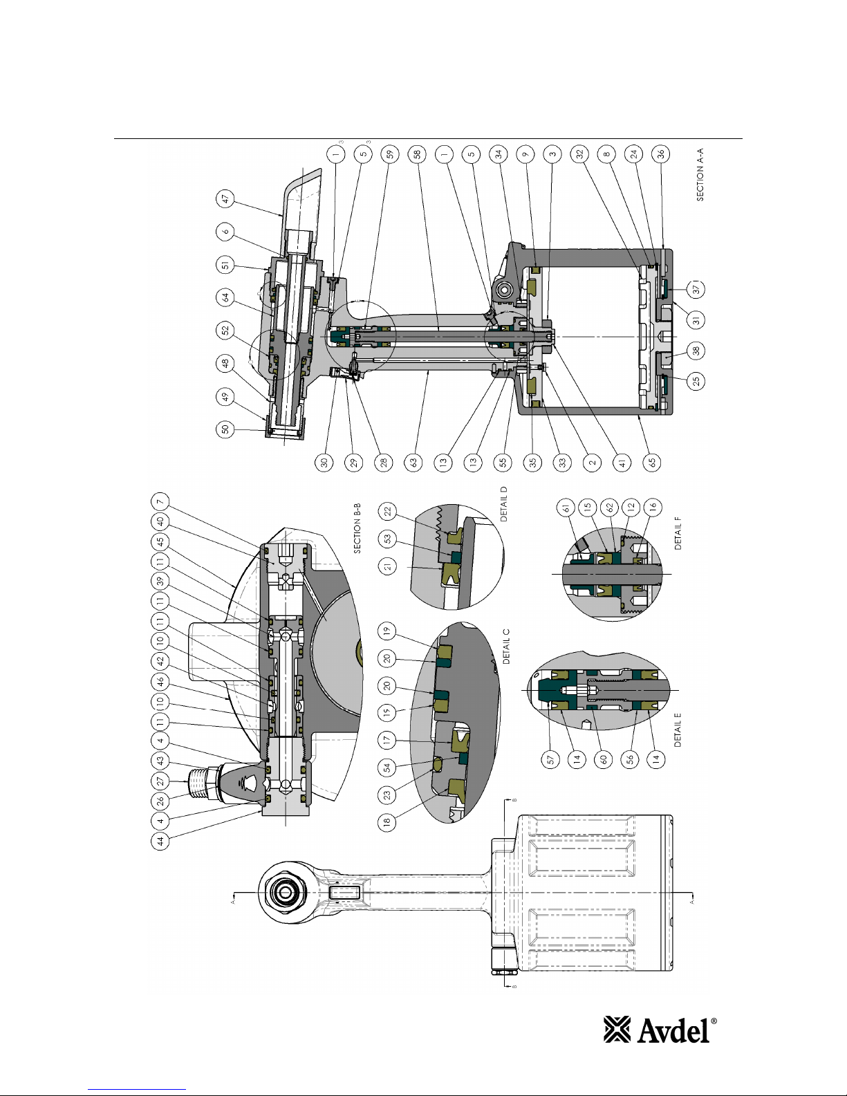
15
General ssembly of Base Tool 73200-02000

16
Parts List for 73200-02000
ITEM NO. PART NO. DESCRIPTION QTY. SPARES ITEM NO. PART NO. DESCRIPTION QTY. SPARES
1 07001-00507 M5 x 8 Socket Hd Screw 4 10 34 73200-02004 Handle Retaining Nut 1
2 07001-00690 Orifice Plug 1 35 73200-02005 Force Reduction Seal 1
3 07002-00200 Nut - M18 x 1.5 1 36 73200-02006 Gasket 1 2
4 07003-00028 O Ring - Swivel Bolt 2 6 37 73200-02007 Sintered Silencer 1
5 07003-00194 M5 Bonded Seal 4 10 38 73200-02008 Locknut - Base Cap 1
6 07003-00277 O Ring - End Cap 1 6 39 73200-02009 Valve Spool 1 2
7 07003-00388 O Ring - Valve Retainer 1 6 40 73200-02010 Valve Retainer 1
8 07003-00469 O Ring - Base Plate 1 6 41 73200-02011 Air Piston Connector 1
9 07003-00470 Quad Ring - Air Piston 1 6 42 73200-02012 Valve Body 1 2
10 07003-00471 O Ring - Valve Minor 2 6 43 73200-02013 Swivel 1
11 07003-00472 O Ring - Valve Major 4 6 44 73200-02014 Swivel Bolt 1
12 07003-00473 O Ring - Seal Retainer 1 5 45 73200-02021 73200 Label 1
13 07003-00474 O Ring - Handle 2 6 46 73200-02022 Safety Label 1
14 07003-00475 Lip Seal - Power & Return 2 6 47 73200-02030 Deflector 1 3
15 07003-00476 Lip Seal - Handle 1 6 48 73200-02041 Adaptor 1 1
16 07003-00477 Pneumatic Lip Seal - Seal Retainer 1 6 49 73200-02042 Retaining Nut 1
17 07003-00478 Lip Seal - Front Head 1 6 50 73200-02043 Adaptor Ring 1
18 07003-00479 Wiper Ring - Front Head 1 6 51 73200-03101 End Cap 1
19 07003-00482 Seal - Head Piston 2 6 52 73200-03102 Seal Housing 1 1
20 07003-00483 Anti Extrusion Ring - Head Piston 2 6 53 73200-03103 Bearing Ring - Rear Head 1 2
21 07003-00484 Lip Seal - Rear Head 1 6 54 73200-03104 Bearing Ring - Front Head 1 2
22 07003-00485 Wiper Ring - Rear Head 1 6 55 73200-03105 Seal Retainer 1
23 07003-00486 O Ring - Hydraulic Seal Housing 1 4 56 73200-03106 Pull Piston 1
24 07004-00109 Retaining Ring - Base 1 3 57 73200-03107 Return Piston 1
25 07004-00111 Retaining Ring - Silencer 1 3 58 73200-03108 Air Piston Rod 1
26 07005-00015 Washer - 1/4" BSP 1 59 73200-03109 Air Piston Rod End 1
27 07005-00041 Double Male Connector - 1/4" BSPF 1 60 73200-03110 Bearing Ring - Rod End 1 2
28 07005-00088 Schrader Valve 1 2 61 73200-03111 Seal Stop 1
29 71210-02008 Trigger 1 2 62 73200-03112 Bearing Ring - Handle 1 2
30 71210-02024 Trigger Pin 1 4 63 73200-03200 Head 1
31 73200-02001 Base Cap Machined 1 64 73200-03300 Head Piston 1
32 73200-02002 Base Plate Machined 1 65 73200-03400 Body 1
33 73200-02003 Air Piston 1

17
Priming
Priming is ALWAYS necessary after the tool has been dismantled and prior to operating. It may also be necessary to restore the full stroke after
considerable use, when the stroke may ha e been reduced and fasteners are not now being fully placed by one operation of the trigger.
Oil Details
The recommended oil for priming is Hyspin® VG32 a ailable in 0.5 litre (part number 07992-00002) or one gallon containers (part number 07992-
00006). Please see safety data below.
Hyspin® VG32 Oil Safety Data
First id
SKIN:
Wash thoroughly with soap and water as soon as possible. Casual contact requires no immediate attention. Short term contact requires no
immediate attention.
INGESTION:
Seek medical attention immediately. DO NOT induce omiting.
EYES:
Irrigate immediately with water for se eral minutes. Although NOT a primary irritant, minor irritation may occur following contact.
Fire
Flash point 232°C. Not classified as flammable.
Suitable extinguishing media: CO2, dry powder, foam or water fog. DO NOT use water jets.
Environment
WASTE DISPOSAL: Through authorised contractor to a licensed site. May be incinerated. Used product may be sent for reclamation.
SPILLAGE: Pre ent entry into drains, sewers and water courses. Soak up with absorbent material.
Handling
Wear eye protection, imper ious glo es (e.g. of PVC) and a plastic apron. Use in well entilated area.
Storage
No special precautions.

18
Priming
Priming Kit
The 73200 Ser ice Kit includes all of the parts needed to prime the tool. Howe er, if required, a Priming Kit can be supplied separately.
PRIMING KIT : 73200-99991
P RT NO. DESCRIPTION QTY.
07900
-
010
6
0
PRIMING
SYRINGE
2
07900
-
0106
1
PULL STROKE SETTER
1
07900
-
01062
RETURN STROKE SETTER
1
07900
-
01063
PRIMING SYRINGE EXTENSION
1
07900
-
01066
STARTER NUT
1
To fit the Pull Stroke Setter and Return Stroke Setter, the following standard tools are needed (not supplied with Priming Kit).
•27mm Spanner
•10mm Allen key
Spanners and Allen keys are specified across flats unless otherwise stated.
Priming Ports
Stroke Setting
The Pull Stroke Setter is used to ad ance the Head Piston 64 to full stroke. The external threads on the Pull Stroke Setter wind into the Head 63,
pushing the Head Piston back. With the Head Piston fully forward, only one side of the Pull Stroke Setter will wind into the Head, as the Head
Piston pre ents thread engagement when using the other side. When the Pull Stroke Setter is wound up to a stop in the Head, the Head Piston
has been ad anced to half of the a ailable stroke. The Pull Stroke Setter is then unscrewed and the other side is wound into the Head, completing
the stroke.
The Return Stroke Setter is used to draw the Head Piston 64 fully forward. The Return Stroke Setter stops against the Head 63, whilst the internal
threads wind on to the Head Piston, drawing it forward. With the Head Piston at full stroke, only one side of the Return Stroke Setter will wind on
to the Head Piston, as the Head pre ents thread engagement when using the other side. When the Return Stroke Setter is wound up to a stop in
the Head, the Head Piston has been returned to approximately half of the a ailable stroke. The Return Stroke Setter is then unscrewed and the
other side is wound on to the Head Piston, returning it to the fully forward position.
When either Setter is used, the Head Piston should not rotate. If necessary, a 10mm A/F Allen key should be fitted to the rear of the Head Piston to
pre ent rotation. It may be necessary to mo e the Head Piston forward with the Starter Nut to allow the Return Stroke Setter to engage the
thread.
* Refers to items included in 73200 Ser ice Kit. For complete list see page 12.
Item numbers in bold refer to the General Assembly drawing and parts list (pages 15 – 16).

19
Priming
Initial Priming Procedure
Follow these instructions if all of the oil has been emptied from the tool, e.g. following tool disassembly and maintenance. If the tool has stroke
loss, follow the Top-up Priming Procedure on page 20.
Follow the Hyperlink below or alternati ely scan the QR-code for a ideo of the Initial priming procedure for this tool.
http://youtu.be/k4g9iT4hhI8
*Bullet numbering below relates each step to rele ant section of the priming ideo
Preparation
①Ensure tool is disconnected from air supply.
①Remo e all bleed screws 1 and seals 5.
①Using soft jaws to hold the tool Handle, position the tool in the nose-down orientation.
Pull side priming
①Ensure tool is disconnected from air supply.
①Remo e all bleed screws before priming.
①Using a 27mm A/F spanner and the Return Stroke Setter*, ensure that the Head Piston 64 is fully forward. Remo e Return Stroke Setter.
①Fit Extension* to one Priming Syringe*.
①Fill both Priming Syringes* with approximately 30ml of oil and remo e any air from the syringes.
①Fit Priming Syringe* to lower pull bleed port.
①Fit Priming Syringe* with Extension* to upper pull bleed port.
②Push oil from the first syringe until no air bubbles are e ident in the second syringe, or until the oil drops below 5ml.
②Push oil from the second syringe until no air bubbles are e ident in the first syringe, or until the oil drops below 5ml.
②Repeat pre ious 2 steps until no air bubbles are e ident.
②E en out oil olumes between each syringe. Including oil and air, the plunger must not be abo e 25ml olume in either syringe.
③Connect tool to air supply.
③Press and hold Trigger. This ensures the Air Piston 33 is at the end of the pull stroke.
③Disconnect tool from air supply.
④Remo e the Priming Syringe* from the lower pull bleed port and reseal this port.
⑤Using a 27mm A/F spanner and both sides of the Pull Stroke Setter*, wind the Head Piston 64 back to 21mm stroke, applying pressure to
the plunger at all times. This ensures that no air is drawn into the system as the Head Piston is pushed back.
⑥With the Head Piston at 21mm stroke, remo e Pull Stroke Setter.
⑦Remo e the Priming Syringe* with Extension* and reseal this port.
Return side priming
⑦Ensure tool is disconnected from air supply.
⑦Ensure Extension* is fitted to one Priming Syringe*.
⑦Fill both Priming Syringes* with approximately 30ml of oil and remo e any air from the syringes.
⑦Fit Priming Syringe* to return bleed port.
⑦Fit Priming Syringe* with Extension* to second return bleed port.
⑧Push oil from the first syringe until no air bubbles are e ident in the second syringe, or until the oil drops below 5ml.
⑧Push oil from the second syringe until no air bubbles are e ident in the first syringe, or until the oil drops below 5ml.
⑧Repeat pre ious 2 steps until no air bubbles are e ident.
⑧E en out oil olumes between each syringe. Including oil and air, the plunger must not be abo e 25ml olume in either syringe.
⑨Connect tool to air supply. This ensures the Air Piston 33 is at the end of the return stroke.
⑨Disconnect tool from air supply.
⑩Remo e Priming Syringe* fitted with Extension* and reseal this port.
⑩Using a 27mm A/F spanner, Starter Nut and both sides of the Return Stroke Setter*, wind the Head Piston 64 forward to 0mm stroke,
applying pressure to the plunger at all times. This ensures that no air is drawn into the system as the Head Piston is drawn forward.
⑪With the Head Piston fully forward, apply reasonable pressure to the plunger to push oil from the syringe up to a stop. Approximately 0.5ml
will be pushed from the syringe into the tool.
⑪Remo e Return Stroke Setter.
⑪Remo e the Priming Syringe* and reseal this port.
Pull and return test
⑫Measure the distance from the end of the Head Piston 64 to the front of the Head 63.
⑫Connect tool to air supply.
⑫Cycle the tool. Measure the distance from the end of the Head Piston to the front of the Head. Ensure the Head Piston stroke is 21mm and
that Head Piston fully returns at the end of the cycle. If not, follow the Top-up Priming Procedure on page 20.
⑫Disconnect tool from air supply. The tool is now primed.
* Refers to items included in 73200 Ser ice Kit. For complete list see page 12.
Item numbers in bold refer to the General Assembly drawing and parts list (pages 15 – 16).

20
Priming
Top-up Priming Procedure
If the tool has stroke loss, follow these instructions. If all of the oil has been emptied from the tool, e.g. following tool disassembly and
maintenance, follow the Initial Priming Procedure on page 19.
Follow the Hyperlink below or alternati ely scan the QR-code for a ideo of the Initial priming procedure for this tool.
http://youtu.be/ZxIkLygiKCI
*Bullet numbering below relates each step to rele ant section of the priming ideo
Preparation
①Ensure tool is disconnected from air supply.
①Using soft jaws to hold the tool Handle, position the tool in the nose-down orientation.
Pull side priming
①Connect tool to air supply.
①Press and hold Trigger. This ensures the Air Piston 33 is at the end of the pull stroke.
①Disconnect tool from air supply.
②Remo e pull bleed screws.
②Fit Extension* to one Priming Syringe*.
②Fill both Priming Syringes* with approximately 30ml of oil and remo e any air from the syringes.
③Fit Priming Syringe* to lower pull bleed port.
③Fit Priming Syringe* with Extension* to upper pull bleed port.
③Push oil from the first syringe until no air bubbles are e ident in the second syringe, or until the oil drops below 5ml.
③Push oil from the second syringe until no air bubbles are e ident in the first syringe, or until the oil drops below 5ml.
③Repeat pre ious 2 steps until no air bubbles are e ident.
④Remo e the Priming Syringe* from the lower pull bleed port and reseal this port.
④Using a 27mm A/F spanner and both sides of the Pull Stroke Setter*, wind the Head Piston 64 back to 21mm stroke, applying pressure to
the plunger at all times. This ensures that no air is drawn into the system as the Head Piston is pushed back.
④With the Head Piston at 21mm stroke, remo e Pull Stroke Setter.
⑤Remo e the Priming Syringe* with Extension* and reseal this port.
Return side priming
⑥Connect tool to air supply. This ensures the Air Piston 33 is at the end of the return stroke.
⑥Disconnect tool from air supply.
⑥Remo e return bleed screws.
⑦Ensure Extension* is fitted to one Priming Syringe*.
⑦Fill both Priming Syringes* with approximately 30ml of oil and remo e any air from the syringes.
⑧Fit Priming Syringe* to return bleed port.
⑧Fit Priming Syringe* with Extension* to second return bleed port.
⑧Push oil from the first syringe until no air bubbles are e ident in the second syringe, or until the oil drops below 5ml.
⑧Push oil from the second syringe until no air bubbles are e ident in the first syringe, or until the oil drops below 5ml.
⑧Repeat pre ious 2 steps until no air bubbles are e ident.
⑧Remo e Priming Syringe* fitted with Extension* and reseal this port.
⑨Using a 27mm A/F spanner, Starter Nut and both sides of the Return Stroke Setter*, wind the Head Piston 64 forward to 0mm stroke,
applying pressure to the plunger at all times. This ensures that no air is drawn into the system as the Head Piston is drawn forward.
⑨With the Head Piston fully forward, apply reasonable pressure to the plunger to push oil from the syringe up to a stop. Approximately 0.5ml
will be pushed from the syringe into the tool.
⑩Remo e Return Stroke Setter.
⑩Remo e the Priming Syringe* and reseal this port.
Pull and return test
⑪Measure the distance from the end of the Head Piston 64 to the front of the Head 63.
⑪Connect tool to air supply.
⑪Cycle the tool. Measure the distance from the end of the Head Piston to the front of the Head. Ensure the Head Piston stroke is 21mm and
that Head Piston fully returns at the end of the cycle. If not, repeat this Top-up Priming Procedure.
⑪Disconnect tool from air supply. The tool is now primed.
* Refers to items included in 73200 Ser ice Kit. For complete list see page 12.
Item numbers in bold refer to the General Assembly drawing and parts list (pages 15 – 16).
Table of contents
Other Avdel Power Tools manuals

Avdel
Avdel 73432-02000 User manual

Avdel
Avdel Genesis G2LB User manual

Avdel
Avdel 7555 User manual

Avdel
Avdel 07281 User manual

Avdel
Avdel Genesis nG2s User manual

Avdel
Avdel Genesis G2LB User manual

Avdel
Avdel 7287 User manual

Avdel
Avdel Genesis G3 HD User manual

Avdel
Avdel Genesis G2LB User manual

Avdel
Avdel 753 MkII User manual

Avdel
Avdel 7432 User manual

Avdel
Avdel Genesis G2LB User manual

Avdel
Avdel 74200 User manual

Avdel
Avdel 71404 User manual

Avdel
Avdel Genesis G1 71204 User manual

Avdel
Avdel Genesis G2HD User manual

Avdel
Avdel 7391 User manual

Avdel
Avdel 74200 User manual

Avdel
Avdel Genesis G2LB User manual

Avdel
Avdel 7536 Operation instructions


