FJ200 -CT USER`S MANUAL V3.0
Page 2
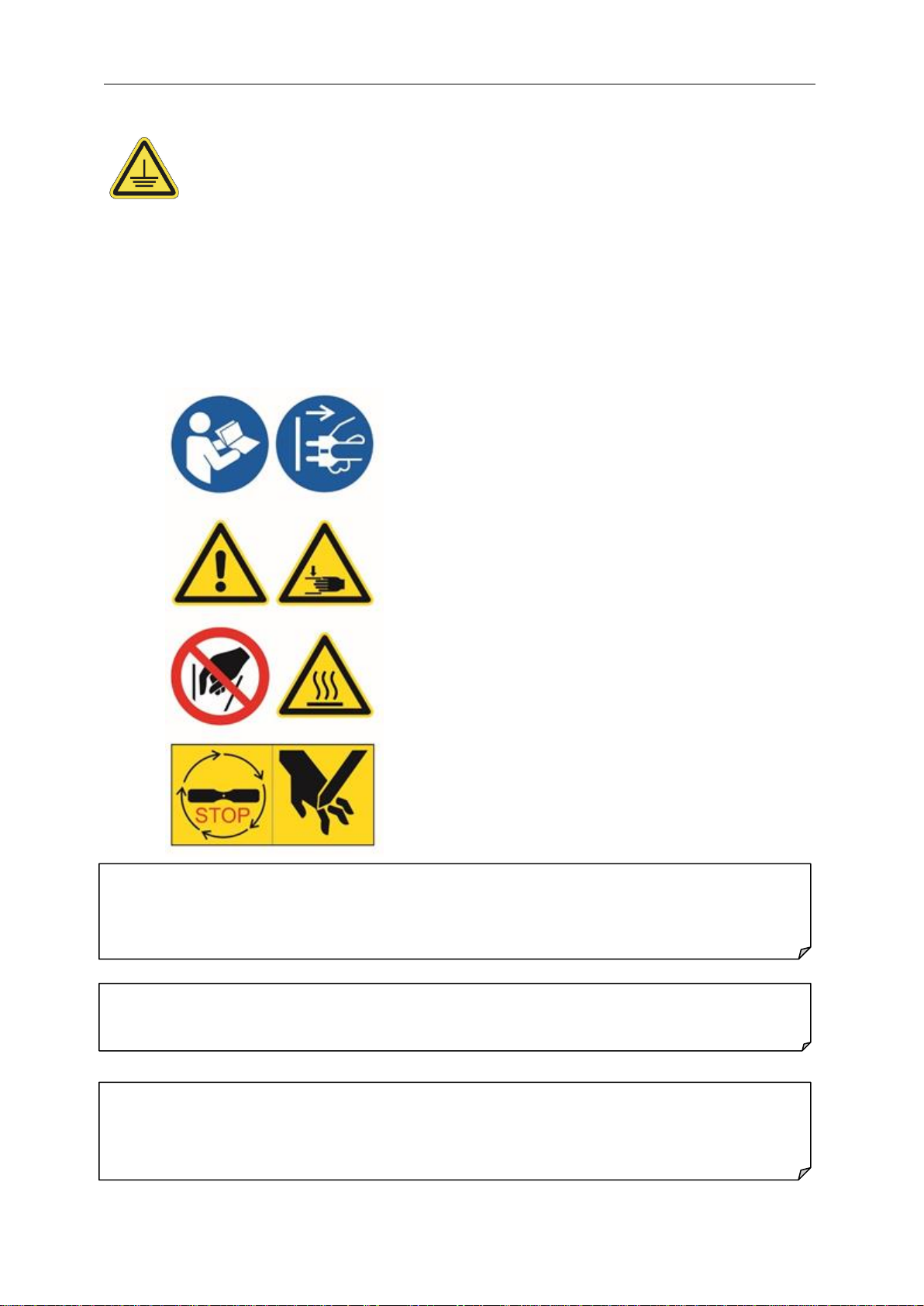
1. GENERAL SAFETY RECOMMENDATIONS
•Before any installation read this manual very carefully.
•When using this device follow instructions in this manual and instructions for safe
work.
oWhen working always wear tight clothes, do not wear a tie.
oProtect long hair with suitable head protection.
oDo not wear jewelery (rings, necklace, etc.).
oWear eye protection –protective glasses.
oBe at full psychofisycal abilities when using this device.
oIlluminate the working area according to regulations.
oAssure the clean and tidy working place, surrounding of the device should
be free.
•Connect the device to a proper electrical socket.
•Only trained personnel is allowed to use this device.
•Before turning on the device always check:
oThat no part of the device is damaged.
oThat moving paths are clear of obstructions.
oThat device is FILLED WITH WATER
•The device has to be switched on by main switch.
•When there is a defect on the device, you must turn it off and put the plug from the
power source.
•Don`t repair the device by yourself, in case of malfunction rather call authorized
service provided by your distributor. Only authorized service with faultless tools
can repair the device.
•Always report every brakedown or defect on device.
•In case of serious malfunctions switch off the main switch and unplug the device
from electrical socket and compressed air socket, then call authorized service.
•You are allowed to use only the procedures that are described in this manual. Use
of any other procedures or adjustments could result in destruction of the device
or injury. Injuries connected with such procedures can not be subject of any
product liability claims.
oDo not reach into danger area –moving parts!
oDo not leave the working area when device is in operation!
oDo not lean the device while in operation!
oDo not remove warning labels or security devices. Blocking or removing
the security devices is forbidden!
•It is forbidden to clean, lubricate or repair the device during operation.
•Disconnect device from electrical socket before cleaning!
•Take care that milk, water or humidity will not come into the device.