Jasic CUT40 (L131) User manual


FORWARD
SHENZHEN JASIC TECHNOLOGY CO., LTD.
Address: No. 3, Qinglan 1st Road, Pingshan District, Shenzhen, Guangdong, China
Postcode: 518118
Tel: 0755-29651666
Fax: 0755-27364108
Website: http://www.jasictech.com
AS60974 and UL60974 standard. Relevant design plans and manufacturing
technologies of this product are patented.
and international standards, and meets GB15579, ICE60974, EN60974,
This product is designed and manufactured according to relevant national
Thank you for JASIC inverter cutter. In order to ensure your safety and
correct operation, please read this manual carefully before operation.
Keep this manual properly for future references.

SAFETY
Precautions for installation
Beware of electric shock!
Install grounding device according to application standard.
Do not touch live parts with naked skin, wet gloves or wet clothes.
Be sure you are insulated from ground and workpiece.
Cover the cover plate of the machine before power on to avoid an
electric shock.
Confirm the safety of your working position.
Beware of fire hazard!
Please install the machine on non-combustible materials to avoid
a fire.
Make ensure there are no inflammables near the cutting position
to avoid a fire.
Beware of explosion !
Do not install the machine in an environment with explosive gas
to avoid an explosion.
Replacing the components can be dangerous.
Only professionals can replace the components of the machine.
Make sure the connecting wires inside the machine are correctly connected after replacing
the PCBs, and then the machine can be run. Otherwise, there is a risk of damage to
property.
Make sure there are no foreign bodies such as wire leads, screws, gaskets and metal bars
falling into the machine inside when replacing the components.

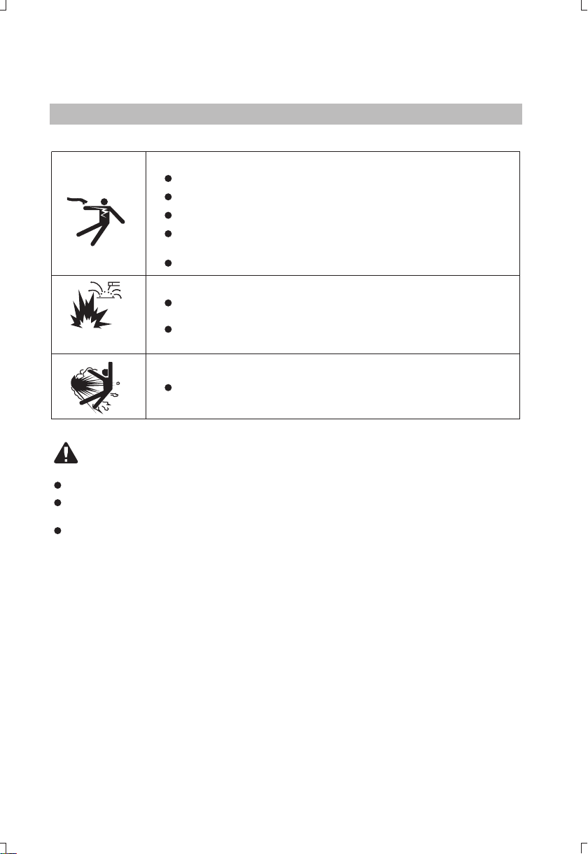
Pay attention to the following when discarding the machine:
Burning the plastic parts such as the front panel may produce poisonous gas.
Dispose it as industrial waste.
cutting
Burning the electrolytic capacitors in the main circuit or on the PCBs may cause an explosion.
Smoke-may be harmful to your health!
Keep your head away from the smoke to avoid inhalation of waste gas
in cutting.
Keep the working environment well ventilated with exhaust or ventilation
equipment when .cutting
Arc radiation-may hurt your eyes and burn your skin!
Use proper mask and wear protective clothing to protect your eyes and
body.
Use proper mask or curtain to protect onlooker from being injured.
Magnetic field can make cardiac pacemaker a bit wonky!
Stay away from the power source to reduce the affect of magnetic filed.
Improper use and operation may result in a fire or an explosion!
Cutting spark may result in a fire, so please make ensure there are no
inflammables near the position, and pay attention to fire safety.cutting
Ensure there is fire extinguisher nearby, and make sure someone has
been trained to operate the fire extinguisher.
Do not weld closed container.
Do not use this machine for pipe thawing.
Hot workpiece can cause severe scald!
Do not touch hot workpiece with bare hands.
Cool the torch for a while after continuously working.cutting
Excessive noise does great harm to people’s hearing!
Wear ear covers or other hearing protectors when .cutting
Give warning to onlooker that noise may be potentially hazardous to
hearing.
Moving parts may injure your body!
Please keep away from moving parts (like fan).
Each door, panel, cover, baffle plate, and protective device the like
should be closed and located correctly.
Seek professional support when trouble strikes!
When trouble strikes in installation and operation, please inspect
according to related contents in this manual.
If you still cannot understand fully, or you still cannot solve the problem,
People with cardiac pacemaker should consult the doctor before carrying
out .cutting
please contact the dealer or the service center of JASIC to obtain
professional support.
Precautions for discard
Precautions for operation

TABLE OF CONTENTS
1. GENERAL DESCRIPTION . . . .
1.1 Model coding . . . . . . . . . . . . . . . . . . . . . . . . . . . . . . . . . . . . . . . . . . . . . . . . . . . . . . . . . . . 1
1.2 Technical parameters . . . . . . . . . . . . . . . . . . . . . . . . . . . . . . . . . . . . . . . . . . . . . . . . . . . . 1
1.3 Size and weight . . . . . . . . . . . . . . . . . . . . . . . . . . . . . . . . . . . . . . . . . . . . . . . . . . . . . . . . . 2
1.4 Composition and configuration of the machine system . . . . . . . . . . . . . . . . . . . . 3
1.5 Functions and characteristics of the machine . . . . . . . . . . . . . . . . . . . . . . . . . . . 4
1.6 System characteristics . . . . . . . . . . . . . . . . . . . . . . . . . . . . . . . . . . . . . . . . . . . . . . . . . . . . 5
2. INSTALLATION AND CONNECTION . . . . . . . . . . . . . . . . . . . . . . . . . . . . . . . . . . . . . . . . . . . 6
2.1 Installation requirements . . . . . . . . . . . . . . . . . . . . . . . . . . . . . . . . . . . . . . . . . . . . . . . . . . 6
2.2 Precautions . . . . . . . . . . . . . . . . . . . . . . . . . . . . . . . . . . . . . . . . . . . . . . . . . . . . . . . . . . . . 7
3. OPERATION . . . . . . . . . . . . . . . . . . . . . . . . . . . . . . . . . . . . . . . . . . . . . . . . . . . . . . . . . . . . . . 9
3.1 Panel functions of L131 . . . . . . . . . . . . . . . . . . . . . . . . . . . . . . . . . . . . . . . . 9
3.2 /L211. . . . . . . . . . . . . . . . . . . . . . . . . . . . . . . . . . . 10
3.3
Notes for cutting operation . . . . . . . . . . . . . . . . . . . . . . . . 12
3.6 Cutting parameters table . . . . . . . . . . . . . . . . . . . . . . . . . . . . . . . . . . . . . . . . . 13
4. MAINTENANCE . . . . . . . . . . . . . . . . . . . . . . . . . . . . . . . . . . . . . . . . . . . . . . . . . . . . . . . . . . . 15
4.1 Daily maintenance . . . . . . . . . . . . . . . . . . . . . . . . . . . . . . . . . . . . . . . . . . . . . . . . . . . . . . 15
4.2 Periodic check . . . . . . . . . . . . . . . . . . . . . . . . . . . . . . . . . . . . . . . . . . . . . . . . . . . . . . . . . 16
5. TROUBLESHOOTING . . . . . . . . . . . . . . . . . . . . . . . . . . . . . . . . . . . . . . . . . . . . . . . . . . . . . . 17
. . . . . . . . . . . . . . . . . . . . . . . . . . . . . . . . . . . . . . . . . . . . . . . 1 . .
.
. .
.
cutting . .
cutting . .
.
.
.
.
.
. . . . . . . . . . . .
Panel functions of L204/L205 . . . . . . .
Panel functions of L201. . . . . . . . . . . . . . . . . . . . . . . . . . . . . . . . . . . . . . . . . . . . . . . . . . . . 11
3.4 Operation method . . . . . . . . . . . . . . . . . . . . . . . . . . . . . . . . . . . . . . . . . . . . . . . . . . . . . . . . 12
3.5 . . . . . . . . . . . . . . . . . . . . . . . . .
. . . . . . . . .
3.7 Replacement of electrode and nozzle . . . . . . . . . . . . . . . . . . . . . . . . . . . . . . . . . . . . . . . . 14
.
.
.
.

Rated input power supply
1
Rated output (A/V)
Rated duty cycle(%)
No-load voltage(V)
Efficiency (%)
1. GENERAL DESCRIPTION
1.1 Model coding
Product code
Code for rated output current
Inverter air plasma cutter
Figure 1 1: Model coding-
1.2 Technical parameters
Table 1 1: General technical parameters-
Items
Models
Single phase
AC220V 50/60Hz
-
Cooling mode
Insulation grade
Power factor
Rated input capacity KVA( )
Output current range (A)
CUT XX (XXXX)
CUT40
(L131)
6.4
40/96
60
230
20-40
0.2-0.4
15.2
10 10/20
60
315
20-1 00
F
0.70 0.93
Arc ignition ode m
Post-flow time (S)
Gas pressure range (Mpa)
Enclosure ingress protection
3 phase AC380/415V 50/60Hz-
CUT100
(L201)
10
60/104
40
310
20-60
0.70
Air cooling
0.3-0 .5
CUT80
(L205)
15
80/112
40
310
20-80
HF
10
IP21S
85
0.70
CUT60
(L204)
CUT60
(L211)
25-60
300
40
60/104
10
0.70

2
1.3 Size and weight
Table 1-2: Overall size and weight of the machine
Figure 1-2: Appearance and size of the machine Unit: mm( )
Weight Kg( )
Model
Overall size (L*W*H)
CUT40(L131)CUT60 L204( )/(L211)
415*155*315 540*250*380 568*259*446
9 17 26.5
CUT100 L201( )
A
L
W
H
W
L
H
CUT80 L205( )
17.4
540*250*380

3
1.4 Composition and configuration of the cutting machine system
1)Composition
Figure 1-3: Composition of the cutting machine system
2 Configuration)
Table 1-3: Configuration of CUT40(L131)
Table 1-4: Configuration of CUT60(L204)/CUT60(L211)
Cutting machine CUT40(L)131
300A-6mm²-KDP16D(3m)
PT-31
Name Specification
Quantity pcs ( )
Remark
Material code
Cutting torch
Earth clamp
Operator’s manual
CUT series
Standard configuration
1
1
1
1
Cutting machine CUT60(L204)/(L211)
300A-16mm²-2.5m
P80 5m 60A( )
Name Specification
Quantity pcs ( )
Remark
Material code
Cutting torch
Earth clamp
Operator’s manual
CUT series
Standard configuration
1
1
1
1
10048248
10003276
10049815
10003276
10049239
10049239

4
1.5 Functions and characteristics of the cutting machine
Cutting machine CUT100(L201)
300A-6mm²-KDP16D(3m)
BP-80 5m
Name Specification
Quantity pcs ( )
Remark
Material code
Cutting torch
Earth clamp
Operator’s manual
CUT series
Standard configuration
1
1
1
1
10048212
10003277
Table 1-6: Configuration of CUT100(L201)
CUT series are inverter cutting machines made by our company with advanced inverter technology.
They are more mature products with stable performance. With PWM technology and high power
component MOSFET (or IGBT), it inverts the DC voltage, which is rectified from 50Hz/60Hz
input AC voltage, to 30K~100KHz AC high voltage. Then the voltage is dropped and rectified to
output the high power DC power supply for cutting. The machine adopts switching power supply
inverter technology, greatly reducing the volume and weight of the cutter, and obviously enhancing
the conversion efficiency by 30%.
Features of CUT series
Economic and practical by adopting compressed air as the plasma gas source. The cutting
speed has increased by 1.8 times when compared with oxyacetylene cutting.
It can cut thick steel plate conveniently and quickly.
It is easy to ignite arc, and post-flow function is available.
It has a wide range of use, especially for cutting stainless steel, copper, cast iron and
aluminum, etc.
With simple operation and high cutting speed, smooth cutting surface can be obtained, and
polishing is unnecessary.
It adopts HF arc ignition mode.
Cutting machine CUT80(L205)
Name Specification
Quantity pcs ( )
Remark
Material code
Cutting torch
Earth clamp
Operator’s manual
CUT series
Standard configuration
1
1
1
1
10049816
10049813
Table 1-5: Configuration of CUT80(L205)
10049239
10049239
300A-16mm²-2.5m
P80 5m 80A( )

5
1.6 System characteristics
Figure 1-4: Duty cycle
Figure 1-5: Output characteristic curves
1) Duty cycle
2) Output characteristics
External characteristic of maximum output
External characteristic of minimum output
Relationship with ratedload
Rated duty cycle refers to the percentage of the normal work time of the machine under rated
maximum current holding in the period when taking 10 minutes as a period. The rated duty cycle
of this machine is 40 -60%. Using the cutting machine continuously overrunning the rated load
may lead to overheating of the machine, and frequently using the machine overrunning the rated
load may accelerate the aging of the machine or even burn the machine.
%
U2(V)
U0
2(A)I
0
CUT40(L131)
CUT100(L201)
CUT60(L204)/CUT60(L211)
CUT80(L205)
Q(%)
100
(A)I
80
60
40
20
150120
90
60
30
0
①④
② ③
①
②
③
④

6
2. INSTALLATION AND CONNECTION
2.1 Installation requirements
In order to ensure personal safety and avoid electric shock, please ground the machine reliably
by connecting the ground wire (yellow-green wire) of the machine to the grounding device in
the switching box.
1) Connection of input cable
A primary power supply cable is available for this cutting machine. Connect the power supply
cable to the rated input power. The primary cable should be tightly connected to the correct
socket to avoid oxidization. Check whether the voltage value varies in acceptable range with a
multi-meter.
The cross section of the leads used in the switching box should meet the requirements of the
maximum input capacity of the machine.
2) Connection of output cable
Connection of cutting torch
Connect the copper nut on the cutting torch to the
gas-electric connector on the front panel of the
machine, and tighten it clockwise to avoid gas
leakage. Insert the quick plug on the work clamp
into the “+” output terminal on the front panel of the
machine, and tighten it clockwise.
Connection of the torch trigger
Insert the plug of the torch trigger on the cutting torch
into the socket of torch trigger on the machine panel.
(For models with pilot arc function, connect the pilot
arc wire on the cutting torch to the terminal for pilot
arc wire on the machine panel.) Install the electrode
into the cutting torch by turning it slowly, and tighten
it. Then, get the nozzle and protective sleeve installed
in sequence.
Connection of earth cable
Insert the quick plug on the earth cable into the quick
socket marked with “ ” at the bottom of the front
panel of the machine, and tighten it clockwise. Clamp
the workpiece with the work clamp at the other end of
the earth cable.

7
Figure 2-1: Installation of the reducer valve
4)Installation of the cutting torch
Figure Installation of cutting torch head 2-2:
2.2 Precautions
1) Make sure the place to install the machine can bear the weight of the cutting machine.
2) Do not install the machine at places where water droplet splash may be produced, such as
near water pipes.
3) Cutting should be carried out in dry environment with humidity of 90% or less.
4) The temperature of the working environment should be between -10℃ and 40℃.
5) Avoid cutting in the open air unless sheltered from sunlight and rain. Keep it dry at all times
and do not place it on wet ground or in puddles.
6) Avoid cutting in dusty area or environment with corrosive chemical gas.
7) Do not carry out cutting with the cutting machine placed on a platform with a pitch greater
than 10°.
3) Installation and operation of the reducer valve
Steps for reducer setting are as follows: start the gas flow; lift the pressure control knob upward;
adjust the gas pressure to the desired value by rotating the knob (rotate to “+” direction to
increase gas pressure; rotate to “-” direction to reduce gas pressure); press down the pressure
control knob to get the knob locked. Drain the water by turning the drain knob when there is too
much water in the filter cup.
-Screw the electrode into the torch head.
-Screw the nozzle into the torch head, and
tighten it.
-Screw the protective sleeve into the torch
head, and tighten it.
-Fix the bracket on the torch head, and
tighten the fastening screw.
Pressure control knob
Connecting frame
Pressure gauge
Gas hose
Filter cup
Drain knob
Torch head
Electrode
Nozzle
Protective sleeve
Bracket
Torch handle

8
Overcurrent/overvoltage/overheating protection circuit is installed in this machine. When the mains
voltage, output current or inner temperature exceeds the set standard, the machine will stop
automatically. However, excessive use (e.g. too high voltage) of machine may also damage the
machine, so please note:
This cutting machine can create powerful cutting current and has strict cooling requirements that
cannot be met with natural ventilation. Therefore the built-in fan is very important in enabling the
machine to work stable with effective cooling. The operator should make sure that the louvers be
uncovered and unblocked. The minimum distance between the machine and nearby objects
should be 25cm.
This machine is of automatic mains voltage compensation, which ensures that the cutting current
varies within the given range. In case that the input mains voltage exceeds the tolerance value,
it would possibly damage the machine. The operator should understand this circumstance fully
and adopt relevant precautions.
Remember to observe the max load current at any moment (refer to the corresponding duty
cycle). Make sure that the cutting current should not exceed the maximum load current. Overload
could obviously shorten the machine's lifespan, or even damage the machine.
A sudden halt may occur with the yellow LED on the front panel on while the machine is of
over-load status. Under this circumstance, it is unnecessary to restart the machine. Keep the
built-in fan working to lower the temperature inside the machine. Cutting can be continued after
the inner temperature falls into the standard range and the yellow LED is off.

9
Figure 3-1: Front panel of L131
Figure 3-2: Back panel of L131
3. OPERATION
3.1 Panel functions of L131
1
2
3
4
No. Part name Function
1
2
3
No. Part name Function
1
2
3
4
1
2
3
4
5
6
7
1 40
L204
4
5
6
7
Overheating
indicator
To indicate the temperature inside the
machine is too high and the machine
is under overheating protection status
when it illuminates.
Digital meter To display the cutting current.
Gas-electric
connector To connect the cutting torch.
Interface for
torch trigger
To connect the control signal of cutting
torch.
Overcurrent
indicator
To indicate the machine is under overcurrent
protection status when it illuminates.
Current control
knob
To adjust the output current value.
“+” output
terminal To connect the earth clamp.
Air reducer
valve
To adjust the pressure of the input
air.
Cooling fan
For heat dissipation through forced
air cooling.
Cable For power supply input.
Power switch
To control the ON/OFF of the input
power of the machine.

10
3.2 Panel functions of L204/L205/L211
1
2
3
Power switch
To control the ON/OFF of the input
power of the machine.
1
2
3
No. Part name Function
Figure 3-3: Front panel of L204/L205/L211
Figure 3-4: Back panel of L204/L205/L211
1
2
3
4
No. Part name Function
Current
control knob To adjust the output current value.
To connect the cutting torch
5
6
7
8
Digital meter To display the cutting current.
Rocket switch
For gas-check/cutting status conversion.
For 2T/4T cutting mode conversion.
Rocket switch
“+” output
terminal To connect the earth clamp.
Overheating
indicator
To indicate the temperature inside the
machine is too high and the machine
is under overheating protection status
when it illuminates.
Air reducer
valve
To adjust the pressure of the input
air.
Cable For power supply input.
“-” output
terminal
1
2
3
4
5
6
7
8
1 60
Power
indicator
To indicate the machine is powered on
when it illuminates.

1
2
4
3
11
3.3 Panel functions of L201
1
2
3
4
No. Part name Function
1
2
3
4
5
6
7
8
9
20 100
5
6
7
8
9
Figure 3-5: Front panel of L201
Figure 3-6: Back panel of L201
Overheating
indicator
To indicate the temperature inside the
machine is too high and the machine
is under overheating protection status
when it illuminates.
Digital meter To display the cutting current.
For 2T/4T cutting mode conversion.
Rocket switch
“+” output
terminal To connect the earth clamp.
Interface for
torch trigger
To connect the control signal of cutting
torch.
Overcurrent
indicator
To indicate the machine is under overcurrent
protection status when it illuminates.
Current control
knob
To adjust the output current value.
To connect the cutting torch
“-” output
terminal
Terminal Terminal for pilot arc.
1
2
3
No. Part name Function
4
Air reducer
valve
To adjust the pressure of the input
air.
Cooling fan
For heat dissipation through forced
air cooling.
Cable For power supply input.
Power switch
To control the ON/OFF of the input
power of the machine.

12
3.4 Operation method
1) Turn on the power switch of the machine, and the power indicator illuminates.
2) Select proper working mode and proper function. There are two working modes available on
the machine panel: 2T and 4T. There are two functions available: normal cutting and metal mesh
cutting. The electrode and nozzle are more easily to wear out in metal mesh cutting.
3) Push the torch trigger on the cutting torch, the cutting machine works.
4) Set cutting current according to the thickness of workpiece.
5) Bring the copper nozzle of the cutting torch into contact with the workpiece (For models with
pilot arc function, keep a distance of about 2mm between the copper nozzle of the torch and the
workpiece.), and then push the torch trigger. After the arc is ignited and started, raise the cutting
torch to the position about 1mm above the workpiece, and start cutting.
3.5 Notes for cutting operation
It is recommended not to ignite the arc in the air if not necessary, for it
will shorten the lifespan of the electrode and nozzle of the torch.
It is recommended to initiate the cutting from the edge of workpiece,
unless penetration is needed.
Ensure spatters fly from the bottom of workpiece while cutting. If spatters
fly from the top of workpiece, it indicates that the workpiece can not be
fully cut because the cutting torch is moved too fast or the cutting current
is too low.
Keep the nozzle slightly touching the workpiece or keep a short distance
between the nozzle and workpiece. If the torch is pressed against the
workpiece, the nozzle may stick to the workpiece, and smooth cutting
is unavailable.
For cutting round workpiece or to meet precise cutting requirement,
molding board or other assistant tools are needed.
It is recommended to pull the cutting torch while cutting.
Keep the nozzle of cutting torch upright over the workpiece, and check
if the arc is moving with the cutting line. If the space is not enough,
don’t bend the cable too much, step on or press upon the cable to avoid
suffocating of gas flow. The cutting torch may be burned because the
gas flow is too small. Keep the cutting cable away from edge tools.
Clean up the spatters on the nozzle timely, for it will affect the cooling
effect of the nozzle. Clean up the dust and spatters on the torch head
after using everyday to ensure good cooling effect.

13
The workpiece is not cut fully. This may be caused by:
The cutting current is too low.
The cutting speed is too high.
The electrode and nozzle of the torch are burned.
The workpiece is too thick.
Molten slag drops from the bottom of workpiece. This may be caused by:
The cutting speed is too low.
The electrode and nozzle of the torch are burned.
The cutting current is too high.
3.6 Cutting parameters table
Select proper current according to the cutting parameters table, workpiece material, cutting
thickness and cutting speed, etc. (The figure in the below table is an approximation.)
Table 3-1: Cutting speed (in) when cutting current is 40Am/m
9876543210.1
0.4
0.4
0.4
1.5
1.5
1.5
1.5
8
8
8
8
0.75
0.75
Cutting thickness (mm)
Mild steel
Galvanized steel
Stainless steel
Aluminum
Brass
Red copper
0.12
0.15
0.15
0.15
2520151050.1
0.1
0.1
0.1
0.3
0.3
0.3
0.2
0.5
0.5
0.5
0.3
1.9
1.9
1.9
0.8
0.5
0.5
Cutting thickness (mm)
Mild steel
Galvanized steel
Stainless steel
Aluminum
Brass
Red copper
Table 3-2: Cutting speed (in) when cutting current is 60Am/m
This manual suits for next models
4
Table of contents
Popular Cutter manuals by other brands

Makita
Makita CE002G instruction manual

Makeblock
Makeblock Laserbox Pro Simple Installation Guide

Thunder Laser
Thunder Laser MARS-130 user manual

Logan Graphic Products
Logan Graphic Products Platinum Edge 850 Instruction and operation manual

Monument
Monument PPC110 Product instructions

Carat
Carat PROFICOUP Series operating manual