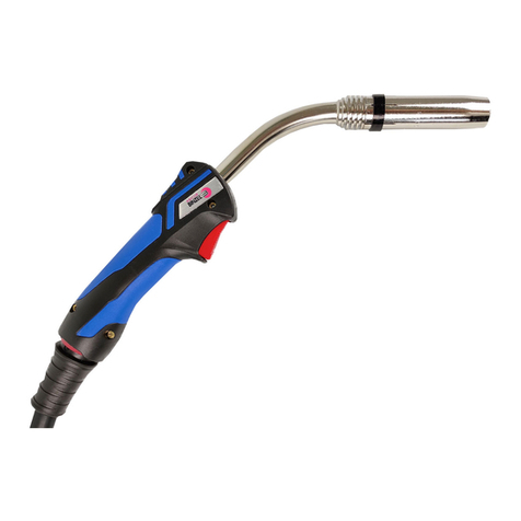
Jasic P150LT User manual

Wilkinson Star Technical
Jasic Cut 160
P150LT Plasma Hand Torch Manual

2
Contents Page
Before starng any cung acvity thoroughly read the operang manual rst to familiarize yourself with the safe and correct
operaon of your Jasic plasma machine. Always ensure that you have suitable eye protecon and protecve clothing. Also take
the necessary steps to protect any persons within the cung area.
Index Page Number
Jasic Cut 160 with P150LT Plasma Torch Overview 3
P150LT Consumable Breakdowns 4
P150LT Torch Informaon 9
Machine torch opon 11
Safety Informaon 12
General Plasma Cung Informaon 13
Stand-o Cung 14
Drag Cung 15
Piercing 16
Bevelling 16
Gouging 17
Plasma Cung Tips and Techniques 18
Plasma Machine Gas Supply - Compressed Air 19
Contact Details 20

3
Wilkinson Star Technical
Jasic Cut 160 Plasma Cung Machine
supplied with P150LT 6m Plasma Hand Torch
P150LT (6m Pt No C1576LT) Torch Specicaons
P150LT (12m Pt No C1578LT)
Duty Cycle : 150 Amps at 60%
Gas Air Pressure - Cung : 76-80 PSI (4.8 - 5.0 bar)
Gas Air Flow : 466 SCFH (220 lpm)
Pilot Arc Ignion : HF
Jasic Plasma Cut 160 Circle Cung
Guide Kit - part number CA2

4
Item No Part Number Descripon Pack Qty
102001 P150LT Torch Head (hand) 1
1a 09706 P150LT Handle c/w Switch 1
1b C1398 'O' Ring - Torch Head 5
1c C1017 Front Insulator - Vespel 1
3C1378 Diuser 1
4C1376 Electrode Hafnium 5
5C1377 Swirl Ring Vespel 1
6C1371 Cung Tip 1.1mm 60A 10
6C1372 Cung Tip 1.35mm 90A 10
6C1373 Cung Tip 1.6mm 120A 10
6C1374 Cung Tip 1.8mm 150A 10
6WB300128 Gouging Tip 2.4mm 100A 10
6C1375 Gouging Tip 3.0mm 150A 10
8C1018 Extended Diuser 1
8a C1517 Extended Electrode 5
9C1369 Extended Tip - Max 50A 10
10 C1001 Extended Tip 1.35 - 90A 10
10 C1002 Extended Tip 1.6 - 120A 10
10 C1003 Extended Tip 1.8 - 150A 10
11 C1389 Nozzle Retaining Cap 1
12 C1393 Contact Nozzle Retaining Cap 1
13 C1007 Spring Holder Protecon Nut 1
14 C1008 Stand O Spring (for C1389) 5
15 C1009 Gouging Spacer (use with item 12) 1
16 C1010 Spacer for Contact Cung (use with items 6, 12 & 22) 1
17 C1406 Gouging Spacer (use with item 11) 1
19 C1014 Shield Cup - Max 50A 1
20 C1015 Spacer for Contact Cung 1
21 C1020 Spacer for Extended Tips (90A and above) 1
22 C1016 Locking Nut 1
23 C1386 Stand O Spring 5
24 C1408 Double Pointed Spacer 1
25 C1409 Crown Spacer 1
27 C1509 Extractor for Swirl Ring 1
28 C3045012 Wrench for Electrode 1
Please Note: Only use the above conguraon for the Jasic Cut 160 model
Jasic Cut 160 Plasma with P150LT 6m Hand Torch
Wilkinson Star Technical
5
Wilkinson Star Technical

Jasic Cut 160 Plasma Machine with P150LT Hand Torch
Stand-o cung setup
Item No Part Number Descripon Pack Qty
102001 P150LT Torch Head (hand) 1
1a 09706 P150LT Handle c/w Switch 1
1b C1398 'O' Ring - Torch Head 5
1c C1017 Front Insulator - Vespel 1
3C1378 Diuser 1
4C1376 Electrode Hafnium 5
5C1377 Swirl Ring Vespel 1
6C1371 Cung Tip 1.1mm 60A 10
6C1372 Cung Tip 1.35mm 90A 10
6C1373 Cung Tip 1.6mm 120A 10
6C1374 Cung Tip 1.8mm 150A 10
8C1018 Extended Diuser 1
8a C1517 Extended Electrode 5
9C1369 Extended Tip—Max 50A 10
10 C1001 Extended Tip 1.35 - 90A 10
10 C1002 Extended Tip 1.6 - 120A 10
10 C1003 Extended Tip 1.8 - 150A 10
11 C1389 Nozzle Retaining Cap 1
12 C1393 Contact Nozzle Retaining Cap 1
13 C1007 Spring Holder Protecon Nut 1
14 C1008 Stand O Spring (for C1389) 5
19 C1014 Shield Cup - Max 50A 1
21 C1020 Spacer for Extended Tips (90A and above) 1
22 C1016 Locking Nut 1
23 C1386 Stand O Spring 5
24 C1408 Double Pointed Spacer 1
25 C1409 Crown Spacer 1
27 C1509 Extractor for Swirl Ring 1
28 C3045012 Wrench for Electrode 1

6
Jasic Cut 160 Plasma Machine with P150LT Hand Torch
Exposed p contact cung setup
Wilkinson Star Technical
Item No Part Number Descripon Pack Qty
102001 P150LT Torch Head (hand) 1
1a 09706 P150LT Handle c/w Switch 1
1b C1398 'O' Ring - Torch Head 5
1c C1017 Front Insulator - Vespel 1
5C1377 Swirl Ring Vespel 1
8C1018 Extended Diuser 1
8a C1517 Extended Electrode 5
9C1369 Extended Tip - Max 50A 1
12 C1393 Contact Nozzle Retaining Cap 1
19 C1014 Shield Cup - Max 50A 1
22 C1016 Locking Nut 1
27 C1509 Extractor for Swirl Ring 1
28 C3045012 Wrench for Electrode 1

7
Jasic Cut 160 Plasma Machine with P150LT Hand Torch
Enclosed p drag cap cung setup
Wilkinson Star Technical
Item No Part Number Descripon Pack Qty
102001 P150LT Torch Head (hand) 1
1a 09706 P150LT Handle c/w Switch 1
1b C1398 'O' Ring - Torch Head 5
1c C1017 Front Insulator - Vespel 1
3C1378 Diuser 1
4C1376 Electrode Hafnium 5
5C1377 Swirl Ring Vespel 1
6C1371 Cung Tip 1.1mm 60A 10
6C1372 Cung Tip 1.35mm 90A 10
6C1373 Cung Tip 1.6mm 120A 10
6C1374 Cung Tip 1.8mm 150A 10
8C1018 Extended Diuser 1
8a C1517 Extended Electrode 5
10 C1001 Extended Tip 1.35 - 90A 10
10 C1002 Extended Tip 1.6 - 120A 10
10 C1003 Extended Tip 1.8 - 150A 10
12 C1393 Contact Nozzle Retaining Cap 1
16 C1010 Spacer for Contact Cung (use with items 6, 12 & 22) 1
20 C1015 Spacer for Contact Cung 1
22 C1016 Locking Nut 1
27 C1509 Extractor for Swirl Ring 1
28 C3045012 Wrench for Electrode 1

8
Jasic Cut 160 Plasma Machine with P150LT Hand Torch
Gouging setup
Wilkinson Star Technical

Item No Part Number Descripon Pack Qty
102001 P150LT Torch Head (hand) 1
1a 09706 P150LT Handle c/w Switch 1
1b C1398 'O' Ring - Torch Head 5
1c C1017 Front Insulator - Vespel 1
3C1378 Diuser 1
4C1376 Electrode Hafnium 5
5C1377 Swirl Ring Vespel 1
6WB300128 Gouging Tip 2.4mm 100A 10
6C1375 Gouging Tip 3.0mm 150A 10
11 C1389 Nozzle Retaining Cap 1
12 C1393 Nozzle Retaining Cap 1
15 C1009 Gouging Spacer (use with item 12) 1
17 C1406 Gouging Spacer (use with item 11) 1
27 C1509 Extractor for Swirl Ring 1
28 C3045012 Wrench for Electrode 1

9
P150LT Plasma Hand Torch
The P150LT plasma torch supplied has the ‘euro style’ power/gas connecon, pilot cable and switch pins connecons.
All Jasic plasma cung systems and torches supplied incorporate a safety circuit to prevent operator injury when changing consumables
etc. This is a simple ring circuit that breaks the electrical torch switching as soon as the retaining cap is removed prevenng machine
operaon. Without such a protecon circuit as previously menoned the open circuit voltage could be as high as 350V DC at the torch
head.
The torch head encompasses a full set of consumables as shown right, these consumables are
made up of a cooling tube, torch electrode, swirl ring for gas distribuon, cung p, retaining
cap and if required a stand o device to ensure the same distance between p and material
being cut.
Plasma Torch Connecon Diagram
Wilkinson Star Technical

10
P150LT Plasma Hand Torch
Fing the P150LT plasma torch
On the Jasic Cut 100 plasma machine, the below torch ng instrucons will need to be observed.
• Locate plasma torch plug into euro connector socket as shown in (Fig 1) image below
• While using the key provided (Fig 6)
• Push and hold in buon in (Fig 2) whilst at the same me rotang the nut clockwise unl fully connected and ght as
shown in Fig 3
• Fig 4 shows the torch screwed in correctly
• Fig 5 shows the torch not fully connected in place Fig 6
Fig 1 Fig 2 Fig 3 Fig 4 Fig 5
Push buon
Wilkinson Star Technical

11
Plasma Machine Torch - PM150LT 6m - Euro (Pt No C1577)
PM150LT 12m - Euro (Pt No C1579)
Current : 50 - 150 Amps
Duty Cycle : 150 Amps at 60%
Gas : Air
Gas Pressure - Cung : 72-87 PSI (5.0-6.0 bar)
Gas Flow @ 125A : 466 SCFH (220 lpm)
Post Flow Time : 45 Seconds
Pilot Arc Current : 15 - 22 Amps
Pilot Arc Ignion : HF
Please Note: Conguraon above only to be used on the Jasic Cut 160
Wilkinson Star Technical
Item No Part Number Description Pack Qty
1b C1398 Torch Head ‘O’ Ring 1
1c C1017 Front Insulator 1
2C1354 Torch Head 1
2a C3055623 Machine Torch Handle 1
3C1378 Air Diuser 1
4C1376 Electrode Hafnium 5
5C1377 Swirl Ring (Vespel) 1
6C1371 Cung Tip (1.1mm) 60A 10
6C1372 Cung Tip (1.35mm) 90A 10
6C1373 Cung Tip (1.6mm) 120A 10
6C1374 Cung Tip (1.8mm) 150A 10
12 C1393 Contact Retaining Cap 1
12 C1006 Contact Retaining Cap (Long Life) 1
18 C1012 Spacer - Machine 1
22 C1016 Locking Nut 1
23 C3045012 Wrench for Electrode 1
24 C1509 Extractor for Swirl Ring 1

12
Plasma Cung Safe Working Pracce
Safety glasses must be worn at all times in addition to welding mask Long and loose hair must be contained
Oil free leather gloves and spats must be worn Sturdy footwear with rubber soles must be worn
Close fitting/protective clothing to cover arms and legs must be worn A welding mask with shade number 11 protective filters must be worn
Respiratory protection devices may be required Hearing protection may be required when cutting thick material
PRE-OPERATIONAL SAFETY CHECKS
• Locate and ensure you are familiar with all machine operaons and controls.
• Ensure material to be cut poses no hazard. Consult the manufacturers' Material Safety Data Sheets (MSDS) for specic technical data and precauonary measures for any materials or
coangs on materials cut with this equipment.
• Check workspaces and walkways to ensure no slip/trip hazards are present, ensure the work leads and hoses do not create a trip hazard.
• Ensure the work area is clean and clear of grease, oil and any ammable materials.
• Keep the equipment, work area and your gloves dry to avoid electric shocks.
• Ensure the gloves, handpiece and work leads are in good condion.
• Ensure other people are protected from ashes by closing the curtain to the welding bay or erecng screens.
• Start the fume extracon unit before beginning cung operaon. Ensure machine is used in a well-venlated area if not used in a welding bay.
OPERATIONAL SAFETY CHECKS
• Ensure machine is correctly set up for current and airow.
• Ensure work return earth cables make rm contact to provide a good electrical connecon.
ENDING OPERATIONS AND CLEANING UP
• Switch o the machine and fume extracon unit when work completed.
• Turn o the air supply and hang up handpiece, hose and welding cables.
• Leave the work area in a safe, clean and dy state.
DON’T
• Do not use faulty equipment. Immediately report suspect equipment.
• Do not weld or cut containers that have held combusble liquids or gases.
• Do not heat or cut metals coated with or containing materials that emit toxic fumes, unless coang is removed from the work surface.
• Never leave the machine running unaended.
This safety page does not necessarily cover all possible hazards associated with plasma equipment safety and should be used in conjuncon with the operang manual along
with other references such as risk assessments. It is designed as a reminder to users prior to equipment use and as a guide to be used to compliment operator training.
POTENTIAL HAZARDS AND INJURIES
Electric shock
Noise
Body burns
Compressed air
Radiaon burns
Fumes
Noxious gas
Flying sparks and falling slag
Wilkinson Star Technical

13
Wilkinson Star Technical
General Plasma Cung Informaon
Before starting any welding or cutting activity ensure that you have suitable eye protection and
protective clothing. Also take the necessary steps to protect any persons within the welding area.
Notes for cung operaon
Do not touch the hot workpiece with bare hands to avoid burning.
It is recommended not to ignite the arc in the air if not necessary, for it will shorten the lifespan of the electrode and nozzle of the torch.
It is recommended to iniate the cung from the edge of the workpiece unless penetraon is needed.
Ensure spaer comes from the boom of workpiece while cung. If spaer comes upwards from the top of workpiece, it indicates that the
workpiece has not been fully cut through. This could be due to not enough power or the cung torch is moved too fast.
For cung a round or shaped piece or to meet precise cung requirement, a stencil board or other tools are needed.
It is recommended to pull the cung torch while cung.
Keep the nozzle of the cung torch upright over the workpiece and check if the arc is moving with the cung line. Do not bend the cable too
much, step on or press upon the cable to avoid restricng the air ow. The cung torch may be burned if the air ow is too low. Keep the cung
cable away from sharp edges.
When the workpiece is nearly cut o, slow down the cung speed and release the torch trigger to stop cung.
Check the torch consumables frequently to prolong the life.
Always ensure the correct consumables are ed in the torch. Incorrect items may cause damage to the torch or machine.
It is recommended that a torch of maximum length of 6 metres is used. If the torch cable is too long, the performance of this cung machine
such as arc ignion will possibly be aected due to the fact that the inner resistance of the cable will reduce the output voltage.
Please Note:
• Your air supply must be free of moisture, water, oil or any other contaminants. Excessive water or oil may cause double arcing, excessive
electrode/p wear or even torch head failure. Contaminants will also cause poor cut quality.
• When starng the arc, ensure you keep the pilot arc me to a minimum to avoid excessive wear on the cung p.
• Do not overghten the electrode when ng a new set of consumables. Over ghtening may cause damage to the internal torch head thread
so that the cung p will not seat correctly.
• Only use the supplied or recommended ’O’ ring lubricant or grease for your plasma torch head, using the wrong lubricant that cannot
withstand high temperatures could cause damage to the plasma torch head.

14
Stand-O Cung
The stand-o cung technique is the process of holding the p of the torch
between 3-4mm from the workpiece to achieve the opmum cut.
Stand-o cung requires a cung p that you need to ensure that the plasma
machines output amperage is matched to the amperage with the p.
Depending on the applicaon the operator may choose to hold the torch ‘free
hand’ away from the plate or could choose to use a stand-o guide to help hold the
torch away from the plate at a xed height, also available are roller guides and
circle cung guide kits which can be very helpful in creang the cuts you want.
To begin cung you would place the torch above the work piece of about 3-4mm,
and begin drawing the p across the workpiece.
You should always start with the torch placed at farthest point from you and then
cut by pulling the torch towards you.
Make sure to keep the torch upright to the material being cut throughout the
cung process.
As you are cung ensure you maintain a smooth and consistent travel speed to
make a clean and precise cut.
There are 3 main reasons why plasma machine operators prefer to use the stand-o
technique rather than drag p cung
It allows for a smoother movement of the torch above the material being cut
without any part of the torch touching the material.
You can comfortably stand the torch while making the contouring process or
following a certain paern.
Because the cung p is not touching the material, this helps to prevent any
blowback of molten material.
Descripon of Stand-o Cung
FREE HAND STAND-OFF CUTTING
STAND-OFF GUIDE CUTTING Wilkinson Star Technical

15
Descripon of Drag Cung
DRAG TIP CUTTING
DRAG SHIELD CAP CUTTING Wilkinson Star Technical
Drag Tip Cung
Drag p cung is the process of dragging the p of the torch along the workpiece to cut the metal.
This is oen the easiest way to cut while minimizing heat input but usually only on cung currents
of 40amps and below. This technique works best when the material being cut is 5mm or less.
Drag p cung does require a ‘drag’ cung p and you need to ensure that the plasma machines
output amperage is matched to the amperage with the cung p.
It can oen be helpful to use a non-conducve straight edge to help maintain a straight cut.
Drag Shield Cap Cung
The drag shield cap opon allows the same technique to be used but having the cung p
insulated (shielded) from the material being cut. Using a drag shield cap allows you to rest the torch
(via the drag cap) on the workpiece while maintaining an opmal 2-3mm stando without touching
the cung p to the material for amperages 40amps and above. (When cung at above 40amps,
touching the p to the work material will adversely aect your cut quality and consumable life).
When you start to drag cut, you would place the p/cap of the torch on the workpiece and begin
dragging (moving) the torch across the workpiece.
You should always start with the torch placed at the farthest point from you and then cut by pulling
the torch towards you while making sure to keep the torch upright to the material being cut
throughout the cung process.
As you are drag cung ensure you maintain a smooth and consistent travel speed to make a clean,
precise cut.
The main benets of drag cung is:
Much easier for the operator because you don't need to maintain a distance between the
cung p and the workpiece. You can simply drag the end of the plasma torch along a
template or a straight edge. This process usually ensures a more accurate cut.
Drag cung produces less spaer and blow back and improves the life of the front end torch
parts.
Best cut quality for material of 5mm or less.

16
Piercing
Piercing is the process in which a quick hole is made in the workpiece. Piercing is oen just a starng hole that will be used to make a
circular cut within the workpiece.
You can use standard cung ps for piercing although ensure the plasma machines output amperage matches the cung ps amperage
rang. No accessories are required when piercing.
The thickness of the material to be pierced will need to fall in the proper amperage range for the machine and p you will be using.
There are two dierent techniques for piercing depending on the thickness of the workpiece. If the work piece is less than 2mm sheet metal,
the torch should be held at a 15°-30° angle with the cung p touching the workpiece.
Begin by establishing the pilot arc, as soon as the pilot arc penetrates the workpiece, use a smooth, rolling moon to move the torch to a 90°
(perpendicular) angle. At this point, the pierce has been created in the workpiece allowing you to begin the cung process. If the material
being cut is thicker than 2mm the torch should be held at a 90° (perpendicular) angle approximately 12mm or more above the workpiece.
Begin by establishing the pilot arc and slowly move the torch towards the workpiece unl the cung arc transfers.
Once the transfer has occurred, hold the torch sll unl the arc exits the boom of the workpiece.
Once the pierce has been made, the torch can be lowered to normal cung height and the cung process can begin.
Bevelling
Bevelling allows you to angle the edge of a at plate or pipe to allow for deeper weld penetraon.
This process is normally used for materials that are 9mm or thicker. You can ulize standard cung ps for bevelling, again you need to
ensure you ulize the correct plasma machine amperage to match the cung ps used.
Ensure that the thickness of the material to be bevelled falls in the amperage range of the plasma machine and cung p that you will be
using. If bevelling by hand, a roller and/or angle guide can be helpful in maintaining the consistent bevel face and the desired angle which is
usually determined by the weld joint design.
The industry standard angle ranges are from 15°-45°. The cung p would normally be between 3–6mm from the workpiece.
Plasma Cung Techniques
Wilkinson Star Technical

17
Gouging
Gouging creates a smooth, clean concaved groove within the material being gouged which is oen weld ready. This process is primarily used
for weld removal or back gouging.
Gouging has specic consumables and sengs depending on the gouge you need to produce which include the gouging p, shield cup and
gas distributor that would be specic to gouging.
To begin the gouging process, hold the p of the torch approximately 12mm from the workpiece angling the torch approximately 20°-40° to
the surface, engage the pilot arc and once established slowly move the p closer to the work piece unl the main arc has transferred. Once
the main arc is established, retract the p unl the distance from the work piece to the p is approximately 15mm.
Make sure that you keep the p of the torch angled approximately 20°-40° during this enre gouging process.
To create a narrow u-groove in the workpiece, the operator should maintain a constant, smooth travel speed.
With this technique the gouge created will be approximately 6mm wide by 6mm deep but this may depend on the gouging p prole.
To create a wider groove, you can oscillate the plasma torch side to side in a half-moon sequence while maintaining a constant, smooth
travel speed. The gouge created will be wider but not as deep. Due to the nature of the gouging process, lead covers, gouging deectors
and torch covers are some accessories that will help to protect the equipment used in the gouging process.
Gouging can be done on all conducve materials.
Before you start gouging, check the torch, consumables, and cables for excessive wear and damage. If the electrode, swirl ring or the cung
p orice shows signs of wear and tear, replace it with a new component that is sized correctly for your unit and applicaon. Cung or
gouging with worn-out consumables only leads to poor cung/gouging performance.
Use clean, dry workshop air (install a lter if necessary) and match pressure and ow requirements to those of the plasma cuer. Adjust the
gas pressure on the machine according to the owner’s manual. For torch leads longer than 6m, add 4 PSI for each addional 6m. Seng the
pressure when the air is owing through the torch will ensure that you have proper pressure and airow while cung.
Plasma Cung Techniques
Wilkinson Star Technical

18
The below is just a few ps on how to get the best cut performance out of your Jasic plasma machine.
Before cung always check the torch, consumables and cables for excessive wear and tear. If the electrode, air distributor or the cung p ori-
ce shows signs of wear and tear then replace it with new consumables sized correctly for your Jasic plasma machine and applicaon your about
to undertake. Cung with worn-out consumables will only lead to poor cut quality.
Only use clean, dry compressed air (always ensure a air lter is installed), ensure you match the air pressure and air ow requirements to those
of your Jasic plasma machine. Adjust the gas pressure on the machine according to the owner’s manual.
Always set the air pressure when the air is owing through the torch, this will ensure that you have proper pressure and airow while cung.
For torch leads longer than 12m, it is common to increase the air pressure by approximately 10 PSI.
Always use the right p for your amperage seng. A lower amperage p has a smaller orice which maintains a narrow plasma stream at lower
sengs. Using a 40-amp p at an 80-amp seng will distort the p orice and will reduce consumable life. Using an 80-amp p on the lower
sengs will not focus the plasma stream as well and lead to a wider kerf.
Use extended ps to reach out further for cung in corners, using paerns or in ght areas.
It is generally best to start a cut from the edge of the plate, hold the torch at 90° to the edge of the workpiece. Press the trigger and pause at the
edge unl the cung arc has completely cut through the material being cut.
When pierce cung, start the pierce just o the cung line in the area of unwanted metal. Angle the torch slightly to direct blowback
molten material away from the torch p (which will greatly extends p life). Once the arc pierces the metal, return the torch to the
perpendicular posion and start moving the torch.
When possible, pull the torch toward you rather than pushing it away from you. On thicker materials it is common to lt the torch back (away
from the cung direcon) about 5°-10° to help minimize dross build up.
When you are cung at the correct speed, the plasma arc under the workpiece should trail the torch at a 5°-10° degree angle. An arc that trails
straight up and down can indicate that your travel speed is too slow, which can produce a cut that is wider than desired, along with an increase
amount of excess dross. An arc with a shallow trail indicates you’re moving too quickly and most likely you will not be severing the metal cleanly.
For straight line cung, use a non-metallic straight edge. Using a piece of mild steel for example as a straight edge can pull the arc towards it
oering a poor cut quality or possibly causing double arcing. A roller guide can prevent this.
Plasma Cung Tips and Techniques
Wilkinson Star Technical

19
Only use compressed air with the Jasic plasma machines
Please Note: NEVER USE OXYGEN
Compressed Air Supplies
Sizing the appropriate compressor to use with your plasma cung machine is as important as supplying
the correct mains power supply.
To get the best out of your plasma cuer you need to supply it with an adequate air supply. The below
are suggested quesons that need to be considered when specifying an air compressor.
• What is the maximum required operang pressure of the plasma cuer?
• What is the maximum required CFM usage of the plasma cuer?
• Does the machine need to be portable or staonary?
• What type of drive do you require? Electric motor or diesel engine?
• What receiver tank size will be needed?
• Generally 3 phase compressors are considered a beer opon than single phase compressors.
The accessories used with the compressor are also important, providing the correct air pressure, air ow which is moisture and oil free is
crucial in ensuring that your plasma will give you quality cuts.
Air Hose: Remember to select the correct bore size, considering demand and length.
Filters: Remove contaminants e.g. water and oil thus prolonging plasma torch consumable life.
Dryers: Refrigerant dryers, high eciency heat exchangers.
Regulators: Allow adjustment to opmum pressure for ecient use of your plasma cuer. Regulate your system to the pressure you need.
Couplings: Heavy air use tools/equipment may need high ow couplings. Size maers.
PLEASE NOTE: Using oxygen in a plasma torch that is designed for air cung can cause a serious re and injury.
Be careful and always follow the manufacturer’s instrucons.
Plasma Machine Gas Supply - Compressed Air
Wilkinson Star Technical

20
Jasic.co.uk
Issue 4 July 2021
Wilkinson Star Limited
Shield Drive
Wardley Industrial Estate
Worsley
Manchester
United Kingdom
M28 2WD
Telephone: 0044 (0)161 728 7900
Email: sales@wilkinsonstar.com
Table of contents
Other Jasic Flashlight manuals