UNV DC5301 User manual

Video Decoder
Quick Guide
Manual Version: V1.00

Thank you for purchasing our product. If there are any questions, or
requests, please do not hesitate to contact the dealer.
Copyright
Copyright 2016 Zhejiang Uniview Technologies Co., Ltd. All rights
reserved. No part of this manual may be copied, reproduced, translated,
or distributed in any form or by any means without prior consent in
writing from our company.
Trademark Acknowledgement
and other Uniview's trademarks and logos are the property of
Zhejiang Uniview Technologies Co., Ltd. Other trademarks, company
names and product names contained in this manual are the property of
their respective owners.
Disclaimer
CAUTION!
The default password is used for your first login. To ensure account
security, please change the password after your first login. You are
recommended to set a strong password (no less than eight characters).
To the maximum extent permitted by applicable law, the product
described, with its hardware, software, firmware and documents, is
provided on an "as is" basis.
Best effort has been made to verify the integrity and correctness of
the contents in this manual, but no statement, information, or
recommendation in this manual shall constitute formal guarantee
of any kind, expressed or implied. We shall not be held responsible
for any technical or typographical errors in this manual. The

contents of this manual are subject to change without prior notice.
Update will be added to the new version of this manual.
Use of this manual and the product and the subsequent result shall
be entirely on the user's own responsibility. In no event shall we be
liable for any special, consequential, incidental, or indirect
damages, including, among others, damages for loss of business
profits, business interruption, or loss of data or documentation, or
product malfunction or information leakage caused by cyber attack,
hacking or virus in connection with the use of this product.
Video and audio surveillance can be regulated by laws that vary
from country to country. Check the law in your local region before
using this product for surveillance purposes. We shall not be held
responsible for any consequences resulting from illegal operations
of the device.
The illustrations in this manual are for reference only and may vary
depending on the version or model. The screenshots in this manual
may have been customized to meet specific requirements and user
preferences. As a result, some of the examples and functions
featured may differ from those displayed on your monitor.
This manual is a guide for multiple product models and so it is not
intended for any specific product.
Due to uncertainties such as physical environment, discrepancy
may exist between the actual values and reference values provided
in this manual. The ultimate right to interpretation resides in our
company.
Environmental Protection
This product has been designed to comply with the requirements on
environmental protection. For the proper storage, use and disposal of
this product, national laws and regulations must be observed.

Safety and Compliance Information
Safety Symbols
The symbols in the following table may be found on installation-related
equipment. Be aware of the situations indicated and take necessary
safety precautions during equipment installation and maintenance.
Symbol
Description
Generic alarm symbol: To suggest a general safety
concern.
ESD protection symbol: To suggest
electrostatic-sensitive equipment.
Electric shock symbol: To suggest a danger of high
voltage.
The symbols in the following table may be found in this manual.
Carefully follow the instructions indicated by the symbols to avoid
hazardous situations and use the product properly.
Symbol
Description
WARNING!
Indicates a hazardous situation which, if not
avoided, could result in bodily injury or death.
CAUTION!
Indicates a situation which, if not avoided, could
result in damage, data loss or malfunction to
product.
NOTE!
Indicates useful or supplemental information
about the use of product.
Safety Information
Installation and removal of the unit and its accessories must be carried
out by qualified personnel. Please read all of the safety instructions
below before installation and operation.

This device is a class A product and may cause radio interference.
Take measures if necessary.
While shipping, the device should be packed in its original packing.
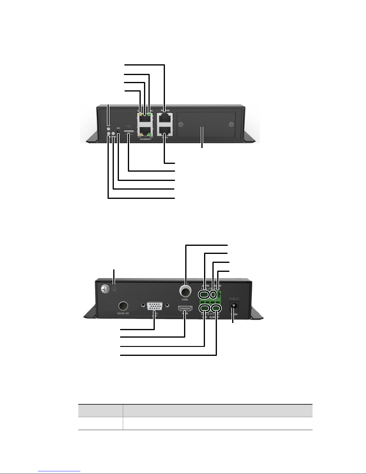
Verify that installation is correct. Incorrect cable connection may
cause personal injury or device damage.
The installation must be made by qualified personnel and should
conform to all the local codes.
If the product does not work properly, please contact your dealer.
Never attempt to disassemble the device yourself. We shall not
assume any responsibility for problems caused by unauthorized
repair or maintenance.
Ensure a proper operating environment, including temperature,
humidity, ventilation and power supply. Make sure the device is
properly grounded and the lightning protection meets
requirements. Keep the device from moisture, dust, strong
electromagnetic radiation and vibration.
Power down the device before connecting and disconnecting
accessories and peripherals.
Protect the power cable from being stepped on or pressed,
particularly at the plug, receptacle, and the part leading out of the
device.
Strictly follow the procedure to shut down the device. Sudden
power failures can cause disk damage and functional abnormalities.
In an environment where power supply is frequently interrupted,
use an Uninterrupted Power Supply (UPS).
Improper use or replacement of the battery may result in hazard of
explosion. Use the manufacturer recommended battery.
Take necessary measures to ensure data security and protect the
device from network attack and hacking (when connected to
Internet). Possible risks and consequences are at user's sole
discretion.

WARNING!
Never look at the transmit laser while the power is on. Never look
directly at the fiber ports and the fiber cable ends when they are
powered on.
Use of controls or adjustments to the performance or procedures
other than those specified herein may result in hazardous laser
emissions.
Regulatory Compliance
FCC Part 15
This equipment has been tested and found to comply with the limits for
digital device, pursuant to part 15 of the FCC Rules. These limits are
designed to provide reasonable protection against harmful interference
when the equipment is operated in a commercial environment. This
equipment generates, uses, and can radiate radio frequency energy and,
if not installed and used in accordance with the instruction manual, may
cause harmful interference to radio communications. Operation of this
equipment in a residential area is likely to cause harmful interference in
which case the user will be required to correct the interference at his
own expense.
This product complies with Part 15 of the FCC Rules. Operation is subject
to the following two conditions:
1. This device may not cause harmful interference.
2. This device must accept any interference received, including
interference that may cause undesired operation.

LVD/EMC Directive
This product complies with the European Low Voltage Directive
2006/95/EC and EMC Directive 2004/108/EC.
WEEE Directive–2002/96/EC
The product this manual refers to is covered by the Waste Electrical &
Electronic Equipment (WEEE) Directive and must be disposed of in a
responsible manner.

i
Contents
1 Overview..............................................................................................1
Packing List....................................................................................................1
Appearance...................................................................................................1
LEDs...............................................................................................................2
2 Installation...........................................................................................3
Preparation ...................................................................................................3
Installing the Dual-SFP Module.....................................................................4
Indoor Installation.........................................................................................4
Outdoor Installation......................................................................................5
Cable Connection ..........................................................................................5
Connecting Cables on the Front Panel .................................................6
Connecting Cables on the Rear Panel...................................................6
Connecting Audio and Alarm Cables ....................................................7
Verification....................................................................................................8
Starting Up the Device ..................................................................................8
3 Login....................................................................................................8

1
1 Overview
The video decoder (referred to as device hereafter) is a new-generation
network media terminal designed mainly for remote video surveillance.
The device can be used with other devices (such as camera) to capture
video images and collect audio from a remote location in real time.
This guide describes the hardware of the device, how to install it, and
how to access it on a web browser.
Packing List
Please check the items in your package carefully. Contact your dealer if
anything is missing or damaged.
Decoder
Phoenix connector terminals (2 pcs)
Mounting brackets (1 pair)
User document
Appearance
The figures are only for reference and may be different from the actual
device.

2
Figure 1-1 Front view
Figure 1-2 Rear view
LEDs
Table 1-1 LED Descriptions
LED
Description
RUN
Blinks: The device is starting up.
RS485/422 port
RUN LED
LINK LED
Ethernet port
ACT LED
Blank filler panel
RS232 port
USB port
CODEC LED
ALM LED
Reset button
DC power input
Audio output
Grounding
Alarm input
VGA output
HDMI output
Two-way audio
Alarm output
CVBS output
Grounding

3
LED
Description
On: The device is operating.
Off: The device is shut down.
ALM
On: A device alarm (e.g., temperature alarm) has occurred.
Off: No device alarm.
CODEC
Blinks: The device is decoding.
Off: The device is not decoding.
ACT
Blinks: The device is transmitting data.
Off: The device is not transmitting data.
LINK
On: The device is connected to network.
Off: The device is not connected to network.
2 Installation
Preparation
Before you start, check against the packing list to ensure all items are
complete.
WARNING!
Do not remove the seal tape on the device chassis. Do not open or
disassemble the device. Contact your local dealer if you need
assistance. We shall not be responsible for damage caused by
unauthorized repair or maintenance.
Do not connect power before installation and cable connection are
completed.
For indoor use, make sure the following requirements are met:
Proper lightning protection for power and other ports (audio, video,
RS485, etc).
Proper grounding through the grounding terminal. For details,
please refer to the DVS_DC Cable Connection Guide.

4
For outdoor use, check that the above requirements are met, and an
outdoor protection box is ready.
Installing the Dual-SFP Module
CAUTION!
Disconnect power before installing the dual-SFP module.
Choose a dual-SFP module recommended by your dealer.
Loosen the screws and remove the blank filler panel. Then, insert the
dual-SFP module and fasten the screws.
Indoor Installation
Install the device in a rack with a frame or holder. If neither frame nor
holder is available, make sure the device is installed securely, and allow
sufficient space on both sides for heat dissipation. Do not stack other
devices on the device.
The steps are as follows. Refer to the Video Encoder/Decoder Frame
Installation Guide or the 1U Holder Installation Guide for details.
1. Install mounting brackets.

5
2. Install the device in the rack.
Outdoor Installation
NOTE!
Choose a protection box that meets standards. Please refer to the
DVS_DC Cable Connection Guide for details.
Use screws to secure the device in the protection box, with ventilation
openings facing upward and downward. Keep at least 10 cm free space
above and below the ventilation openings to ensure effective heat
dissipation.
Cable Connection
CAUTION!
Disconnect power before connecting cables.
Choose cables that meet standards. Please refer to the DVS_DC
Cable Connection Guide for details.

6
Connecting Cables on the Front Panel
Connecting Cables on the Rear Panel
Network
Connect to network
with a network cable
Connect to a device
with a serial cable
Alarm output
device
Power input
Alarm input device
Audio output
device
Display
device
Display
device
Display
device

7
Connecting Audio and Alarm Cables
NOTE!
The alarm output device shall use a DC power supply, and the voltage
and current must not exceed 12 V and 0.7 A.
Table 2-1 Phoenix Connector Terminal Description
Terminal
Description
ALM IN: 1–4
Alarm input.
AUDIO: O, G
Audio output. O for audio signal output, and G
for grounding.
LINE: 1, G, G, O
Reserved.
ALM OUT: 1+, 1-, 2+, 2-
Alarm output.
G
Grounding.
1 2 3 4 G G O G
ALM IN AUDIO
I G G O
LINE 1+ 1- 2+ 2-
ALM OUT
Alarm input
device
Power
+
-
Audio output
device
Alarm output
device

8
Verification
WARNING!
Installation and cable connection must be completed properly before the
device is connected to power. Otherwise, bodily injury or device damage
may occur.
Verify the following before connecting the device to power:
The device is properly installed.
The device is grounded properly, and all cables are connected
correctly.
The power input voltage is stable.
Starting Up the Device
After you complete the above procedures, connect the device to power.
Check the operation status according to Table 1-1.
3 Login
You can access the device using a Web browser from a computer.
Before you start, check that:
The device is operating properly.
The computer is connected to the device on a network.
The computer is installed with Microsoft Internet Explorer (IE) 7.0
or higher, and no proxy server is being used.

9
NOTE!
The default IP address is 192.168.0.14, the default subnet mask is
255.255.255.0, and the default gateway address is 192.168.0.1.
Use admin as the username and password for your first login.
Change the default password on the User page to ensure security.
Follow the steps to log in to the device:
1. Open the IE and then enter the IP address of the device in the
address bar.
2. On the login page, enter your username and password and then
click Login.
3. When logged in, manage and configure the device as needed. To
log out, click Exit in the upper right corner.

BOM: 3101C0E9
Table of contents
Other UNV Media Converter manuals