2 / 4
1
+
-
2 3
Click!
1.
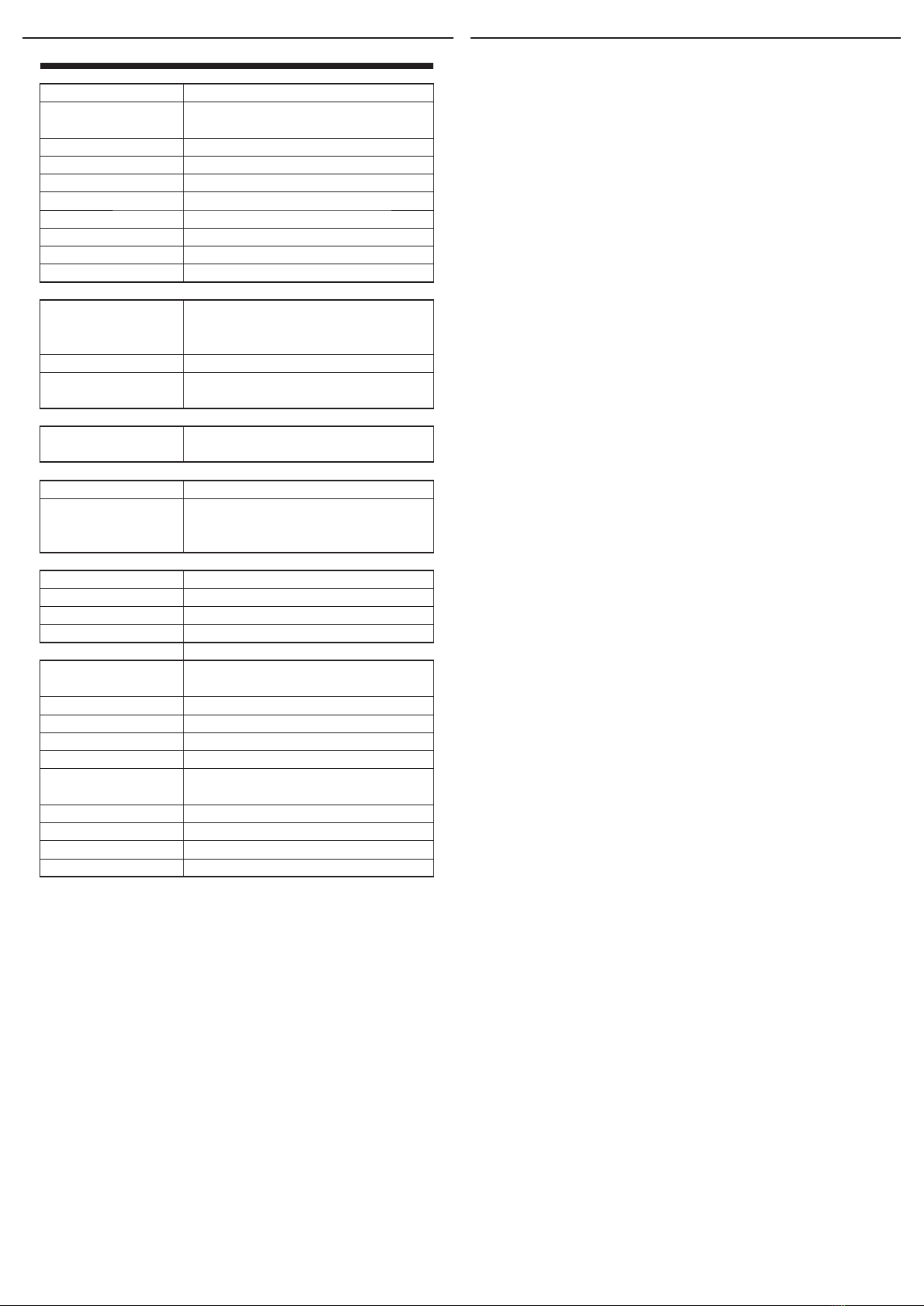
S0
S0
- +
- +
OC(+)
2.
VCC
Signal
GND
+ OUT
+ -
SN
Function
When the power is connected, the transmitter sends the initial message to the server.
Any unauthorized interference with a device, regardless of the feature set, immediately
sends the message to the server.
1. S0 - pulse counting S0
• Checking the correct pulse readings: after setting the longer push (> 2) function of
the SET button, the LED will be activated, which will ash when counting the pulse.
The LED ashes with a short press or automatically after 5 minutes.
• Measured values send the sensor every 4 hours, or immediately when the 5000 pulse
limit is exceeded.
• Recommended accessories: cable for S0 output
2. Energy measurement - pulse counting from active sensor LS, MS, WS
• Checking the correct pulse readings: after setting the longer push (> 2) function of
the SET button, the LED will be activated, which will ash when counting the pulse.
The LED ashes with a short press or automatically after 5 minutes.
• Measured values send the sensor every 4 hours, or immediately when the 5000 pulse
limit is exceeded.
• Recommended accessories
- LS (LED sensor): is particularly suitable for power meters that support LED pulse
sensing
- MS (magnetic sensor): is particularly suitable for gas meters that support magnetic
sensing.
- WS (magnetic sensor for water meter): it is particularly suitable for water meters that
support magnetic sensing.
• Wiring of LS, MS and WS sensors: (+) brown wire, (-) white wire, (OUT) green wire.
Recommendations for installation
• Ensure the correct location - see Warning.
• Prior to attaching the AirTM-100, check the length of the connected sensor and the lo-
cation of the scanned device.
• The working position is arbitrary but the grommet should not be directed upwards.
• The product does not require special handling and maintenance.
When handling a device unboxed it is important to avoid contact with
liquids. avoid unnecessary contact with the components of the device. Do
not touch the metal objects inside the unit.
Safe handling
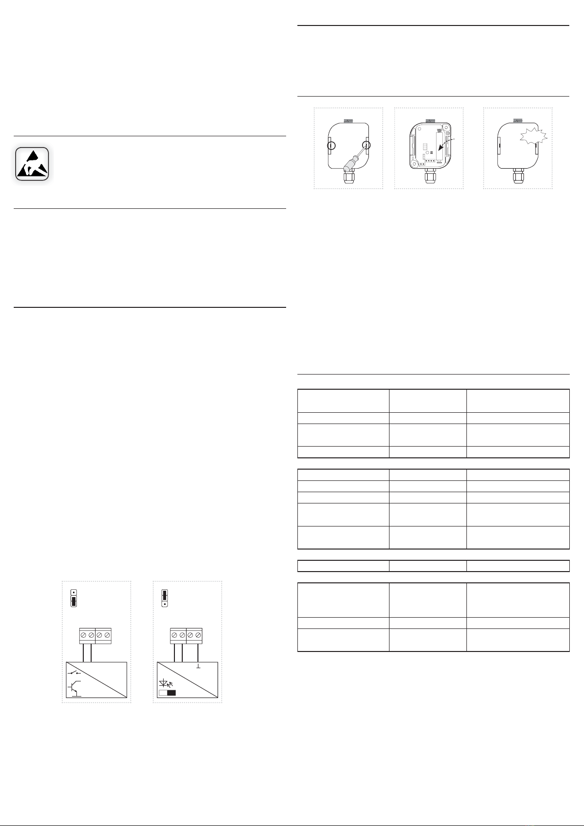
Restart
• Open the cover. Power interruption (remove the battery from the device).
• Press SET> 1min.
• Connect power (insert battery). Close the cover.
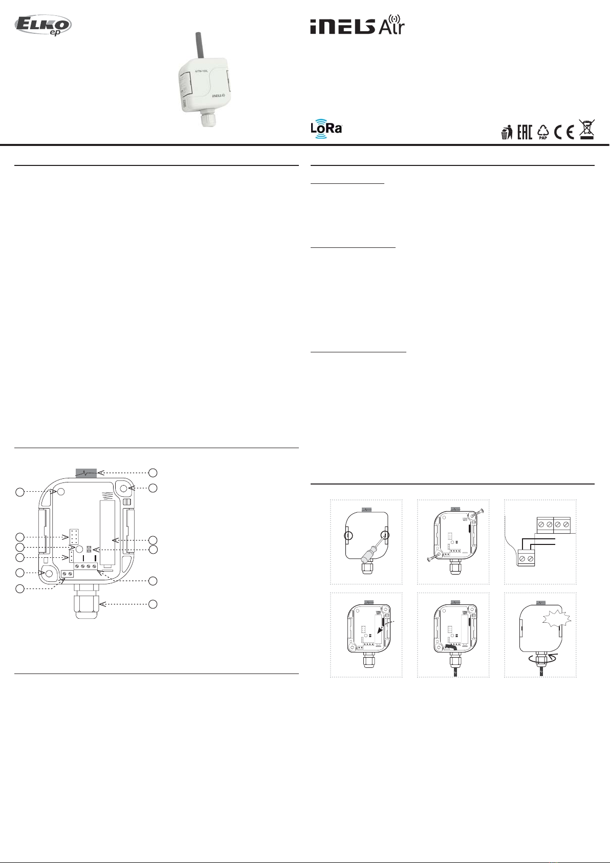
Replacing batteries
1. Using a at-blade screwdriver gradually slide it into one and then the other groove in
the lid and swing open the cover.
2. Remove the discharged battery and insert a new battery into the holder. Beware of
polarity. Both LEDs will ash 3 times (see device status indication).
3. Replace and snap the front cover.
Notice:
Only use batteries designed for this product correctly inserted in the device! Immediately replace
weak batteries with new ones. Do not use new and used batteries together. If necessary, clean the
battery and contacts prior to using. Avoid battery shorts! Do not dispose of batteries in water or
re. Do not dismantle batteries, do not try to charge them and protect them from extreme heating
- danger of leakage! Upon contact with acid, immediately rinse the aected area with a stream of
water and seek medical attention. Keep batteries out of the reach of children. If it is suspected that
the battery has been swallowed or somehow placed inside the body, consult a doctor immediately.
Give the doctor information about the type of battery (from battery case, device or its manual, etc.)
to determine the chemical composition of the battery. Batteries must be recycled or returned to an
appropriate location (e.g. collection container) in accordance with local legal provisions.
Setting functions:
• Long press SET (> 5s) to enter programming mode.
• The green LED will ash by function (function 1 - 1x, 2 - 2x).
• Short (<1s) by pressing the SET button to move upwards in the function selection, press
(> 2 / <5s) longer to go down the function selections.
• Pressing the button (> 5s) long saves the set function and restarts the device.
6. Fill the jumper onto the adjustment pins (see the Function chapter).
7. Replace and snap the front cover. When closing, the handles have to be snapped to their
original position. To ensure the degree of protection, tighten the grommet carefully.
* The glue must meet the optimal conditions for product placement (inuence of tem-
perature, humidity ...)
** For example, a screw or screw of max. Ø 4 mm can be used as a suitable fastener mate-
rial, 13 mm (distance to the partition in the box) must be added to the required length
for attachment to the substrate.
power supply (external or battery),
reset unit
Search availability BTS
error MAC / error MODULU
start unit ok
opening the cover
non contact / contact magnet
test, cancel,„long press“
setting mode (signaling of
measurement / pulses)
impulse LS / MS / WS / S0,
temperature measurement, ...
sending / receiving data
it is necessary to disconnect the power
supply (external or battery), after 60 seconds
after the LED goes out, insert the battery
the battery may be discharged
a discharged battery or a damaged
product
Device states
Indication
3 x R + G blinks
2 x ashes R (2xR _ 2xR _ ...)
5 x ashes R (repeatedly)
1 x ashes R
without indication
3 x ashes G
1 x ashes G
2 x ashes G
1 x ashes G
1 x ashes R
any LED lights
still indicates start
without indication
When the tamper is pressed, the LED is turned o!
Note:
R... LED red
G... LED green
* 1) Indicates only when you press SET> 2 s (setting mode)
* 2) Planned
Unit initialization
Start
Search for BTS * 2)
SIM ERR *2)
ERR *2)
Successful network connection * 2)
Measurement
Tamper
Magnet
SET button short press (< 2s)
SET button longer press (> 2s
/ <5s)
Measurement signaling * 1)
Communication
Communication
Other known states
Does not respond to the SET
button
The unit is still in reset
The unit does not respond even
after removal insert the battery