ACTIVITY DESCRIPTION
The Jäspi GTV Hybrid 500 energy heater is suitable alongside all forms of energy, both heat pumps and traditional heating modes. Product
design has been based on versatility, space friendliness and advanced energy economy.
Hybrid accumulators are energy accumulators developed alongside low-temperature systems (e.g. heat pumps and solar energy) that provide heating
of a waterborne floor and/or radiator system and hot water. Hybrid bookers are suitable for both new and renovation sites. The water space of the
500-liter Hybrid Accumulator is divided into two parts; a top of 300 liters and a lower part of 200 liters separated by an intermediate bulkhead with
a flow channel. At the bottom of the 200 litres, which serves as the buffer tank for the heating circuit, a solar charging spiral and a preheating spiral
of domestic water are located. The top 300 liters store energy for the needs of the domestic water cycle.
Jäspi Hybrid heaters are ideally
suited to all heat pumps on the
market, e.g. alongside rapidly
increasing air-to-water heat
pumps. If the consumption of
domestic water is consistently
particularly high,
or if the property has a po-
reamme, we recommend
connecting the Jäspi water heater
to the Hybrid Heater.
To ensure the yield of heating and
hot domestic water, the hybrid
heater heat pump combination is
always equipped with spare heat
sources, e.g. electricity. Jäspi
Elbox (6kW + 6 kW) is available
as an accessory for hybrid
accumulators
+ Power watch automation). Jäspi
Elbox's power guard car
automation enables efficient use
of the main fixed fuse by taking
into account the rest of the
property's electrical load.
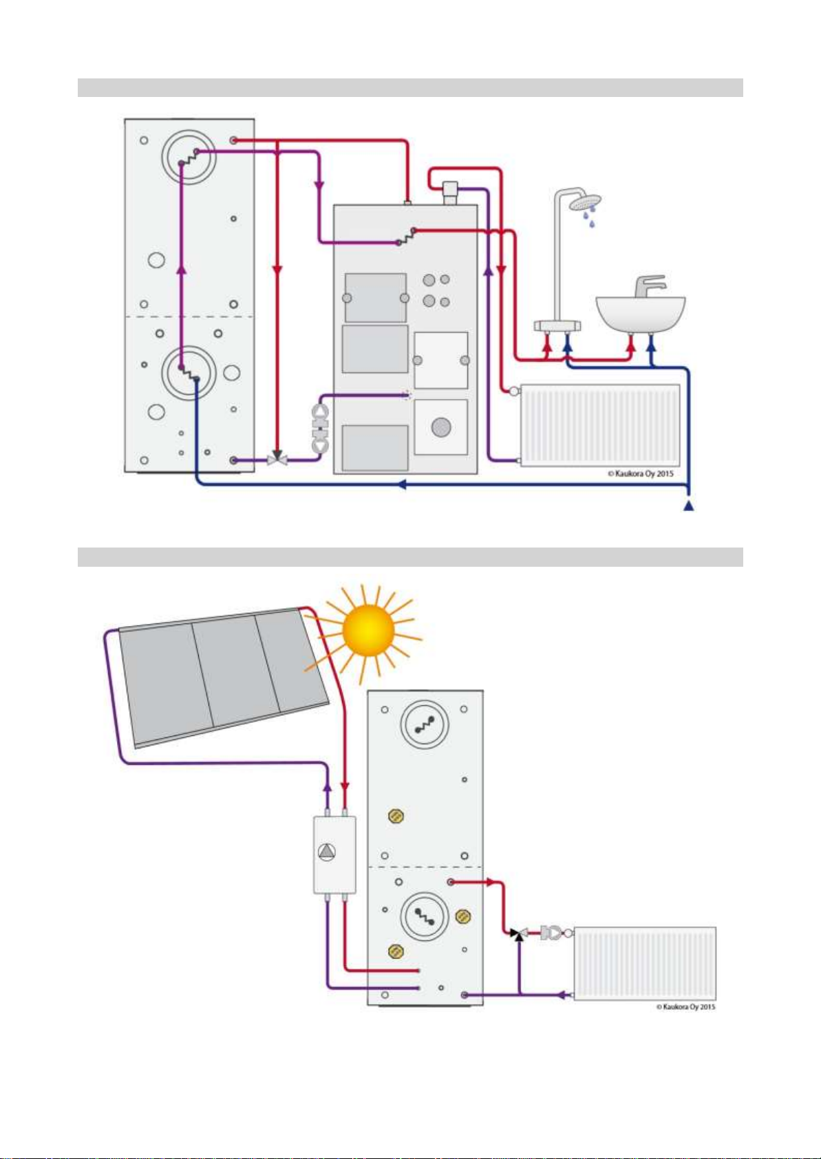
1 Temperature distribution and combinations in hybrid use
Figure 1 shows the temperature distribution of the boiler water in hybrid use, where the upper part of the accumulator is heated hotter than the lower
part of the accumulator. The intermediate bulkhead below the halfway point of the boiler prevents the hot water at the top of the tank and the hot
water at the bottom of the tank from being mixed without need.
Entities:
A: Domestic water charging, inlet to tank / Heating circuit, output from tank
B: Domestic water charging, output from tank / Heating circuit, inlet to tank
C: Charging low temperature heating, inlet to tank / Low temperature heating circuit, output from tank
D: Low temperature heating charge, output from tank / Low temperature heating circuit, input into tank
S1: One S2 of the domestic water firing
resistance: One S3 of the auxiliary heating
element: One of the emergency heating
resistance
More detailed coupling images can be found at the end of the operating instructions.