JAWA B User manual

1
Specification and
Operator's Manual
WITH SPECIAL REFERENCE TO SERVICING AND
ROUTINE MAINTENANCE OF MOTORCYCLES
YEZDI 250 cc MODEL ‘B’
JAWA 250 cc MODEL 353/04
Manufacturers
IDEAL JAWA (INDIA) PRIVATE LTD.,
MYSORE 570 002, SOUTH INDIA

2

3

4

5
INDEX
I SPECIFICATION AND OPERATOR'S MANUAL Page
1. Technical data 7
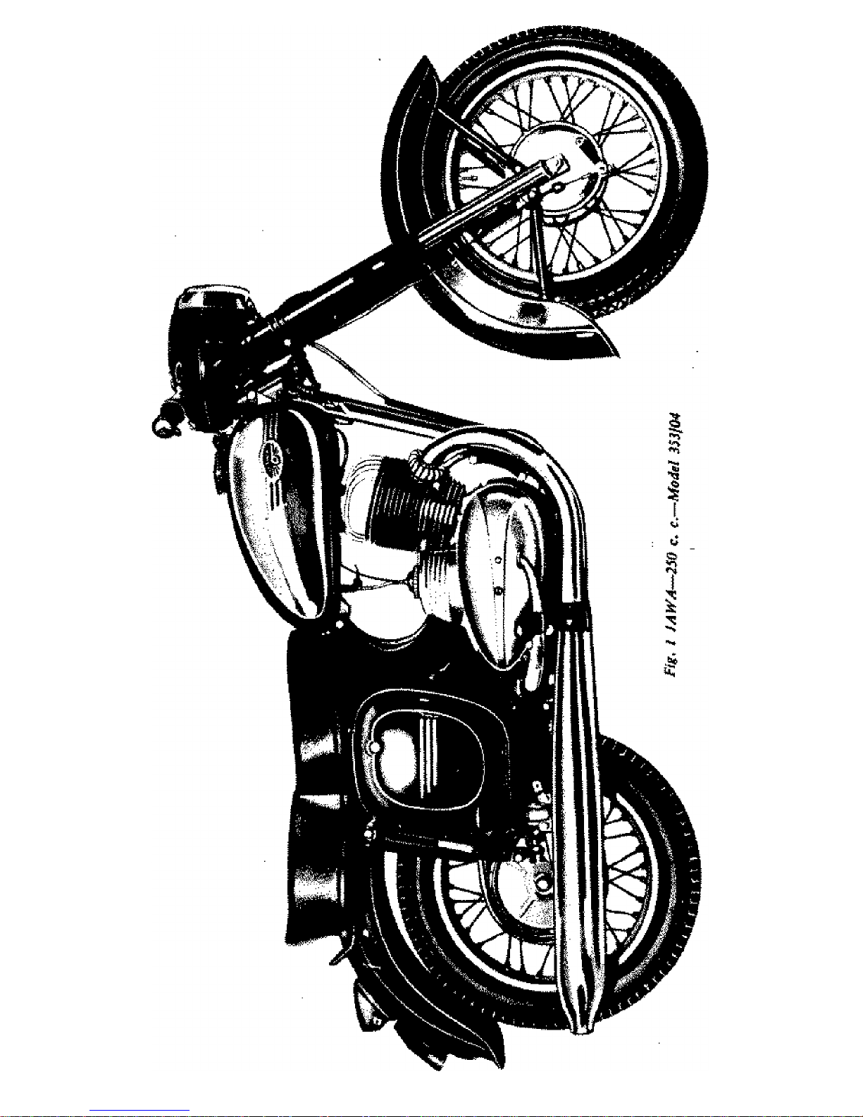
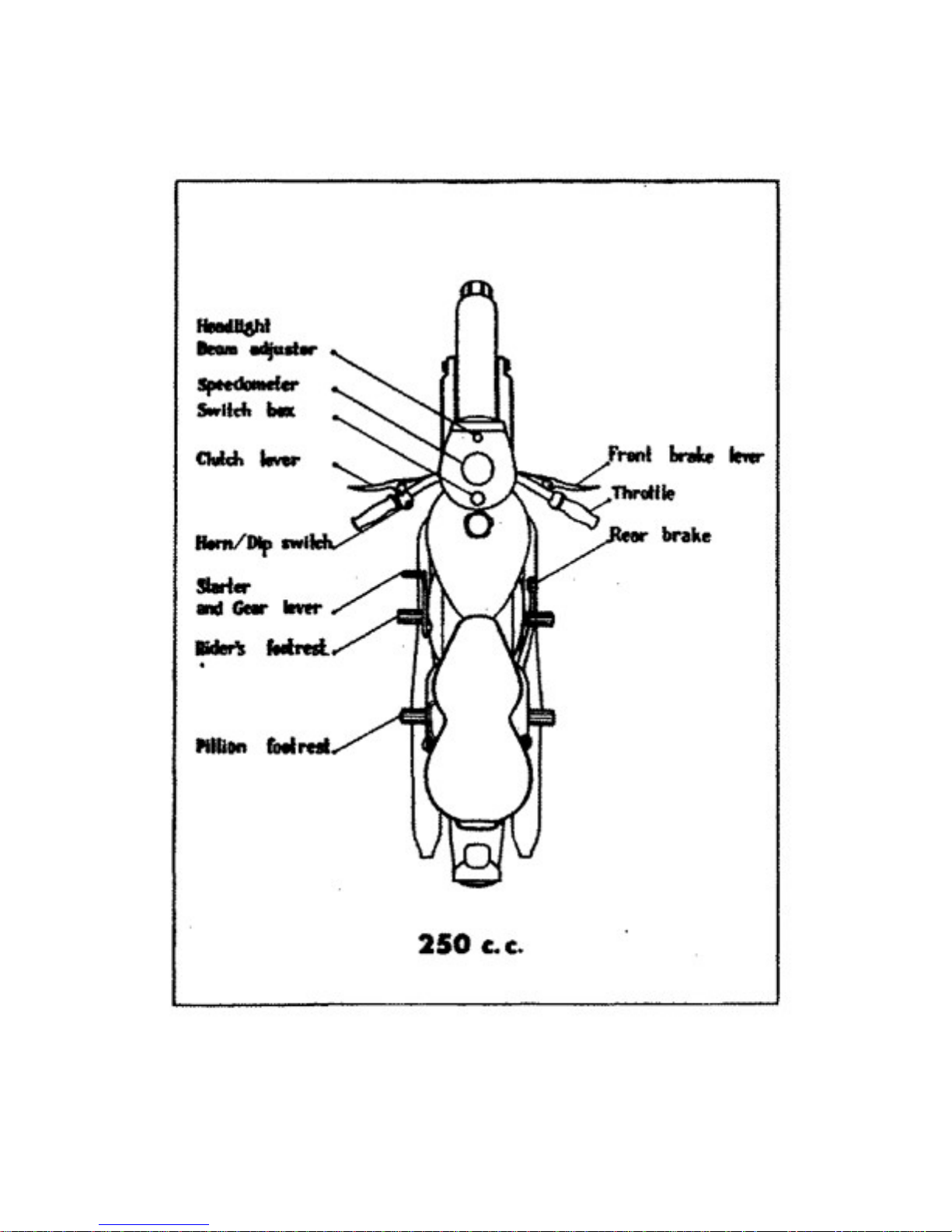
2. Description of motorcycle 10
3. Electrical equipment description 13
4. Running a new motorcycle 18
5. Servicing instructions 20
6. What should be avoided 23
II MAINTENANCE
1. Cleaning the motorcycle 24
2. Lubricating the motorcycle 25
3. Adjusting the brakes 30
4. Tyres 30
5. Adjusting the chain 33
6. Adjusting the clutch 34
7. Carburettor 35
8. Electrical equipment maintenance 38
9. Decarbonisation 41
III DISMANTLING AND ASSEMBLING WITHOUT THE AID OF SPECIAL TOOLS
1. Removing the front wheel 43
2. Removing the rear wheel 44
3. Removing the chaincase and the chain 45
4. Removing the rear chainwheel 45
5. Replacing the wheel ball bearings 45
6. Removing the cylinder head and barrel 49
7. Replacing the piston rings 50
8. Removing the carburettor 50
9. Dismantling the clutch 51
10. Dismantling the headlamp 51
11. Dismantling the steering head and fork legs 53
12. Handlebars --- twist grip 55
13. Removing the dual seat 55
14. Removing the fuel tank 55
15. Removing the cowls 55
16. Dismantling the rear suspension 56
17. Pivoted Fork 57
18. Removing the battery 58
19. Dismantling the switch box 58
20. Removing the engine from frame 59
21. Removing the R.H. and L.H. engine covers 59
IV DEFECTS, CAUSES AND REMEDIES 60
Two-stroke engine operation 63

6
LIST OF ILLUSTRATIONS
1. JAWA 250 c.c. ... model 353/04 24. Removing the front wheel
1a. Yezdi Model 'B’ 25. Taking out the rear wheel spindle
2. Engine 250 c.c - sectional view 26. Dismantling the chaincase
3. Plan of the Motorcycle 27. Rear wheel brake drum ...
exploded view
4. Induction silencer - sectional view 28. Front wheel ... sectional view
5. Electric wiring diagram 29. Rear wheel ... sectional view
6. Stop switch 30. Disconnection the exhaust pipes
7. Oil filling and inspection hole 31. Removing the cylinder head
8. Fuel tap positions 32. Removing the cylinder barrel
9. Butterfly air valve 33. Fitting the piston rings
10.Lubrication chart - L.H. side 34. Front fork -- sectional view
11.Lubrication chart - R.H. side 35. Lubricating the steering head
bearing balls
12.Draining the gearbox oil 36. Lubricating the steering head
bearing balls
11.Removing the chain 37. Adjusting the twist grips
connecting link 38. Removing the dual seat
14.Adjusting the brake 39. Disconnecting the rear suspension
damper top bracket
15.Rim and tyre - sectional view 40. Pivoted rear fork bushing -- sectional
--fitting the tyre cover 41. Removing the battery
16.Correct tyre fitting 42. Two-stroke engine operation diagram
17.Adjusting the chain
18.Chaincase lid
19.Clutch operation diagram
20.Adjusting the clutch
21.Carburetter, flange type
22. Removing the fuse
23.Exhaust silencer - sectional view

7
TECHNICAL DATA
1. TECHNICAL DATA 250 c.c Model 353/04
------------------------------------------------------------------------------------------------
Engine Two-stroke, air-cooled
Number of cylinders One
Bore 65 mm
Stroke 75 mm
Cylinder capacity 248.5 c.c.
Compression ratio 7.2 to 1 (YEZDI - 7.6 to 1)
Engine output 12 BHP (YEZDI - 13 BHP)
Fuel consumption at steady 60 km.p.h 3 litres/100 km
(37 m.p.h) (93 m.p.gallon)
Fuel tank capacity 13.5 litres (Jawa); 14.5 litres (Yezdi)
Maximum speed 105 km.p.h
(65 m.p.h)
Maximum climbing ability (fully laden) 45%
Dimensions of motorcycle --length 1980 mm
--height 1025 mm
--width 670 mm
Weight of motorcycle --dry 128 kg (Jawa); 131 kg (Yezdi)
--inc. fuel 140 kg (Jawa); 144 kg (Yezdi)
Carrying capacity (payload) 160 kg
Front wheel spindle maximum load 85 kg
Rear wheel spindle maximum load 214 kg
Primary drive of 3/8 x 3/8 in. chain 60 links
Final driver by 1/2 x 5/16 in. chain 120 links
Primary and final drive ratios:
Primary 45/22 T
Final 46/19 T
Bottom gear 24/12 x 19/12
Second gear 20/16 x 19/12
Third gear 17/19 x 19/12
Top gear 1/1 direct
Overall gear ratios:
Bottom gear 15.675 to 1
Third gear 9.800 to 1
Second gear 7.013 to 1
Top gear 4.952 to 1
Overall kickstarter ratio 3.41 to 1
Speedometer drive ratio 5/11 T
internal expanding brakes dia 165/35 mm
Braking distances from 40 km.p.h
(25 m.p.h) front wheel brake 30.8 m. (101.05 ft.)
rear wheel brake 30.8 m. (101.05 ft.)
both brakes applied 12.5 m. (41.01 ft.)
Front fork maximum stroke 130 mm (51/3 in.)
Pivoted rear fork maximum stroke 100 mm (3 15/16 in.)
Carburettor 2926 SBD
wheels Interchangeable
size of rims 1.85 B x 16 in.
size of front tyres 3.00 or 3.25 x 16 in.
size of rear tyres 3.25 x 16 in.

8
Fig. 2. Engine 250 c. c.- sectional view

9
Fig .3. Plan of the Motorcycle

10
2. DESCRIPTION OF MOTORCYCLE
The 250 c.c is a solo motorcycle suitable for carrying one or two persons.
The power unit is a two-stroke, air-cooled petrol engine with inverted scavenging.
The engine has a quiet run, well balanced within its extent of revolutions, without
vibration and is capable of lively acceleration.
The clutch is a five-plate friction clutch, fitted with cork lined steel plates running
in an oil bath. Clutch control by hand lever fitted on L. H. side of the handlebars.
The gearbox is of the four-speed type, forming with the crankcase a monoblock
engine unit.
The gear shifting is foot operated by means of a lever located on the L. H. side of
the engine. When changing gear, the declutching is automatic.
Fig. 4 Induction silencer - sectional view
1. Induction silencer cover 5. Clamp
2. Air cleaner 6. Rubber sleeve
3. insert 7. Butterfly air-valve
4. Silencer body 8. Fastening strap
The starting of the engine is foot operated by means of the same lever as gear
shifting and is effected by depressing the shaft and rotating the lever into the
starting vertical position. As soon

11
as the engine starts running the lever returns automatically into the horizontal
position.
The power transmission is by means of chains. The primary chain is enclosed
by the L.H. crankcase cover and runs in oil bath. The final or secondary drive
chain which connects the gear box sprocket to the rear chain wheel is also fully
enclosed by means of a chain case and this arrangement makes the chain last
much longer. The rear chain wheel is coupled with the wheel (brake-drum) by 6
large rubber blocks fitted on the lugs of the chain wheel and engaging into the
chambers (ribs) cast in the brake-drum face. These rubber blocks also act as
efficient dampers, absorbing practically all the shocks of the power and
transmission units and has a very favourable influence on the life of the chain as
well as the vital engine parts (giving the vehicle a smooth CUSHION drive).
The spoke wheels are interchangeable and easily detachable - the spindles being
of the push-out type. The number of spokes is 36 in each wheel - the spoke dia
being 3.5 mm - thread M4.
The brakes are of full width hub and very efficient. The fins along the brake-drum
circumference greatly facilitates in the transfer of heat resulting from braking and
contributes to unchanged braking efficiency during continuous braking and on
long runs. The front brake is controlled by hand lever fitted on the right hand side
of the handle bars, and the rear brake by foot lever located on the right hand side
of the engine. Brakes are easily adjustable without the aid of any tools.
The frame is built up of square section welded tubes with a pivoted rear fork.
The fuel tank is a sheet steel pressing. It is fitted, with a filler cap dia. 60 mm
(2.36 in.), and a fuel tap with filter, It has an emergency fuel reserve of approx. 1
litre (l pts.).
The dual seat with foam-rubber padding is very comfortable. Together with the
rear suspension it offers a superior ride to both driver and the passenger. The
dual seat is detachable and covers an auxiliary box for tyre inflator and spare
parts.

12
The handlebars of 22 mm (55/64 in.) outer diameter have a width of 670 mm
(263/8 in.). They are of one piece, the clutch and front brake cables being
adjustable by means of grub screws at the handlebar levers.
The front suspension consists of a telescopic fork with hydraulic dampers. It is
of the straight slider type with two cylindrical coil springs. The suspension
elements are protected by steel cover tubes. In the top portion of the front fork
stanchion tubes air valves are fitted through which compressed air escapes at the
down-stroke of the suspension.
The rear suspension operates on a circular path. The pivoted rear fork is sprung
by two cylindrical coil springs and fitted with hydraulic dampers. The suspension
dampers are protected by chromium plated steel covers.
The motorcycle could be 'locked by means of an ordinary pad-lock. A bracket has
been located for this in the L. H. side of the steering head, and the motorcycle
could be locked after completely turning the handlebars to the right.
List of Tools: -
Tyre lever with hook Spanner
Tyre lever
Double Ended Spanner 22/19
Double Ended Spanner 17/14
Double Ended Spanner 13/12
Double Ended Spanner 10/9
Double Ended Spanner 7/6
Combined Spanner 32/22
Tube Spanner 10 mm
Tube Spanner 14 mm
Tube Spanner 17 mm
Tommy Rod
Screw Driver 1
Tool Kit -Bag

13
3. DESCRIPTION OF TECHNICAL EQUIPMENT
Ignition and lights are effected by an A. C. Magdynamo. The magdynamo is a
small alternator in which rotor (permanent magnet) while rotating in fixed coils of
the stator induces the current required for the ignition of the mixture as well as
for the lights and the charging of the battery. The three circuit system is arranged
so that the ignition and the headlamp main beam are supplied direct from the
magneto alternator, whereas the battery serves exclusively as an auxiliary source
for the parking light, the tail lamp, stop light, horn and also to facilitate easy
starting.
The magneto stator is secured by two M6 bolts and clamps to the crankcase. The
entire housing can be rotated through 36 degrees for ignition advance setting. The
contact breaker complete is fitted on the stator. Its position on the stator is located
by the manufacturers by means of an Oscillograph to ensure most suitable
tension for ignition and lighting, and this position should never be altered under
any circumstances.
The terminal base fitted on to the stator has the following terminal numbers: -
Number 11 Voltage supply for Ignition
“ 20 Voltage supply for battery charging
“ 55 Voltage supply for Head Light
The rotor is fitted on to the Crank Shaft and held by a bolt together with the cam
controlling the contact breakers.
The battery-14 AML, 6V - with lead plates and electrolyte (diluted sulphuric acid)
is located in the L. H. side box and connected to the frame with its positive (plus)
pole. A 15 Amp. fuse is fitted in a case next to the battery.
A Rectifier (which converts the A. C. magneto current to D. C. for the charging
of the battery) is located on the battery box and is accessible after the dual seat
has been removed. It does not require any maintenance and any manipulation
whatsoever with it should be avoided.

14
The switch box is built into the headlamp and distributes the magneto and
battery current to the accessories.
The terminal plate (at the bottom) of the switch box has the following terminal
numbers
Number 11 for ignition - connected to terminal No. 11 of magdynamo base plate.
“ 15 For ignition connected to terminal No. 15 of H. T. Ignition coil.
“ 21 For battery charging connected .to terminal No. 21 of the rectifier.
“ 30 Connected to negative terminal of battery.
“ 30 Two leads from this terminal (1) to horn and (2) to stop light switch.
“ 55 For Head lights - connected to terminal No. 55 of magdynamo base
plate.
“ 56 For Head lights - connected to Dip switch on Handlebars.
“ 58 Two leads from this terminal (1) to parking light and (2) to tail light.

15
SWITCH KEY POSITIONS
POSITION 1
Engine not running. Key rammed or partly inserted. All appliances
horn and stop-light arc off. Day riding Key inserted. Ignition and
charging circuits commit & accept fully.
POSITION 2
Night riding in town. Key fully inserted Ignition and charging
circuits connected, Pilot Light and Tail Lamp on. Battery gets
charged at increased revolutions.
Patting: With the key removed both bulbs remain on, but the other
circuits are cut.
POSITION 3
Highway night riding. Key fully inserted, Ignition and charging
circuits connoted, the pilot light and Tait lamp are on. The Head-
lamp main bulb is supplied with current from magdynamo direct.
To switch from main beam to dipped beam, use dip-switch on
handle bars.
Battery gets charged at increased revolutions.
POSITION 4
Riding on battery. Key fully inserted, Ignition Coil connected with
the battery direct, the charging circuit connected
This position is to be used for easy starting only.
Battery discharges in this position and hence the key should be
switched on Position 1 after the engine starts.

16

17
Other Electrical Accessories:
The Head lamp is fitted with a 12V-35/35 W double filament bulb with Ba 20d
Socket. The pilot bulb 6 V - I.5 W with Ba 9s socket is also fitted in the head lamp.
Tail lamp bulb - 6 V 5 W
Stop light bulb - 6 V 8 W
The electric Horn 6 V - 2 Amps fitted under the head lamp is fed by the battery
and is operated by a push button on the dip switch.
The H. T. Ignition coil is fitted to the frame underneath the fuel tank.
The condenser of value - 0.2 mF is placed on the frame in the vicinity of
the ignition coil. The condensor lead is connected to terminal No. 1 of the ignition
coil.
The sparking plug used either MICO HB - W 175 Zi or KLG F70. The stop light
switch is located in the R. H. side tool box.
Fig. 6. Stop switch diagram
All connections are of varnish coated automobile leads.
The lead terminals are brass or soldered. The leads from magneto to switch box;
dip switch to main bulb; and sparking plug leads have 1.5 mm2 (0.002 sq. in) in
section and the remaining leads 1 mm2 (0.0015 sq. in.).

18
4. RUNNING A NEW MOTORCYCLE
When taking over a new machine and before making the first trip the customer is
advised to check the equipment of the motorcycle as well as the oil level in the
gearbox and in the front suspension dampers. The oil level in the gear box can be
checked by the oil level inspection hole closed by the oil level screw M6 x 8. For
filling up with oil see Part II, para 2, "Lubricating the Motorcycle". To check the
correct oil level in the hydraulic suspension dampers depress the front and rear
of the motorcycle in turn as much as possible, release quickly and check the recoil
for smooth, bounceless movement. Or ride for a short distance on a rough road
and check the front and rear suspension respectively for bouncing, knocking,
noise and rattle. It should be pointed out that the riding comfort on this type of
motorcycle depends above all on the proper operation of the hydraulic dampers.
A new motorcycle just as a new motor car requires careful running if the engine
is to attain a long life. Only with such running in it is possible to harmonize the
contact faces of all the moving parts smoothly so as to avoid local overheating of
the friction faces and possible damage to them.
It is thus clear that the basic condition of good running in is not to use high
engine power for given time, i.e. to keep the speed down according to the table
below and to observe the following instructions :
a) Mix oil with petrol in the approved ratio as follows ; During the running-
in period of first 1500 kms. (900 miles) at a ratio of 1 to 16, i.e. 62
millilitres of oil to one litre of petrol (1/2 litre of oil to 8 litres of petrol)
and thereafter at a ratio of 1 to 20, i.e. 50 millilitres of oil to one litre of
petrol (1/2 litre of oil to 10 litres of petrol).

19
The lowest and highest speeds in the individual gears for motorcycles not run-in
(i.e. to the mileage 1500 km. or 900 miles)
1st gear … … … 10 – 18 km. p.h.
(6 – 11 m.p.h)
2nd gear … … … 18 – 30 km. p.h.
(11-19 m.p.h.)
3rd gear … … … 25 – 42 km. p.h.
(16-26 m.p.h.)
4th gear … … … 35 – 60 km. p.h.
(22-37 m.p.h.)
b) Table showing speed to be maintained and carburetter setting with reference
to mileage.
Kms (miles)
covered
Tolerated
Maximum
speed
Carburetter setting
Needle
position
Pilot air screw
slackened by
Upto 1500 km.
(900 miles)
1500 km to 3000
km.
(900 to 1850
miles)
Over 3000 km.
(1850 miles)
60 km. p.h
(37 m.p.h)
75 km. p.h
(47 m.p.h)
not limited
4th notch
from top.
3rd notch
from top
3rd notch
from top
¼ turn
½ turn
½ turn
Note : During the running-1n period, the carburetters are set for a rather
rich mixture. It is necessary in the interest of fuel consumption to adjust
the needle position and the pilot air screw in the course of running in
accordance with the above table.
c) When slowing down to a stop keep the engine at idling speed.
d) Check periodically all screws and nuts for slackness and after covering approx.
200 km. (120 miles) tighten the spoke nipples. We are especially pointing out the
necessity to tighten well the engine fixing screws (2 in the front and 2 in the rear
- the rear screws are accessible after removing the L. H. side box).

20
e) Change the oil in the gearbox after the first 500 km. (300 miles). Repeat this
operation after 1500 km. (900 miles). See Part II, Para 2, "Lubricating the
Motorcycle".
f) After the first 1000 km. (600 miles) change damper oil in front fork dampers.
See Part II, para 2 "Lubricating the Motorcycle".
5. SERVICE INSTRUCTIONS
A. Before starting
Make sure there is fuel in the tank. Open fuel tank filler cap by turning it
anticlockwise. Keep filler cap breathing hole clean. After running in the
motorcycle mix oil with fuel at a ratio of 1 to 20 (at a ratio 1 to16 during the
running in period).
Fig. 7. Oil filling and inspection hole
The fuel tank is fitted with a lever type fuel tap. This fuel tap ensures an
emergency fuel supply for about 20 km. (12 miles), depending on the terrain and
speed. Should this fuel reserve be exhausted tilt the machine to the left thus
bringing the remaining fuel from the R.H. half of the fuel tank to L.H. half, i.e. to
the fuel tap. This last reserve will do for about 4 km. (2.5 miles).
This manual suits for next models
1
Table of contents
Other JAWA Motorcycle manuals

JAWA
JAWA F 350/634-5,8 User guide

JAWA
JAWA 300 CL 2020 User manual

JAWA
JAWA 638 Instruction manual

JAWA
JAWA ZVL 210 User manual

JAWA
JAWA 1992 350/638 Instruction manual

JAWA
JAWA 350 Instruction manual

JAWA
JAWA 250 TRAVEL User manual

JAWA
JAWA RVM-600 User manual

JAWA
JAWA 559/04 User guide

JAWA
JAWA Dandy MJ50 User manual