JAWA ZVL 210 User manual

www.jawamoped.com
WORKSHOP MANUAL
moped model 210
This workshop manual is intended primarily
for all repair shops and their workers
concerned with repairs of our model 210
moped. It does not contain servicing jobs
and repairs described in the Rider's Manual
but only repairs for which special assembly
tools and jigs are required.
The purpose of this manual is to facilitate
the work of the repairmen and to improve
servicing of our products. Any changes and
deviations from standard procedures will be
announced in our Service Bulletins.
ZVL concern, Povazske strojarne
Klementa Gottwalda works
sales and technical service department
CONTENTS
I. Moped specifications
II. General technical data
1. Assembly tools and jigs
2. Moped lubrication — Lubrication Chart
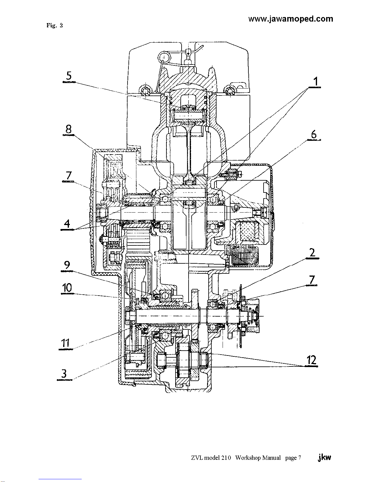
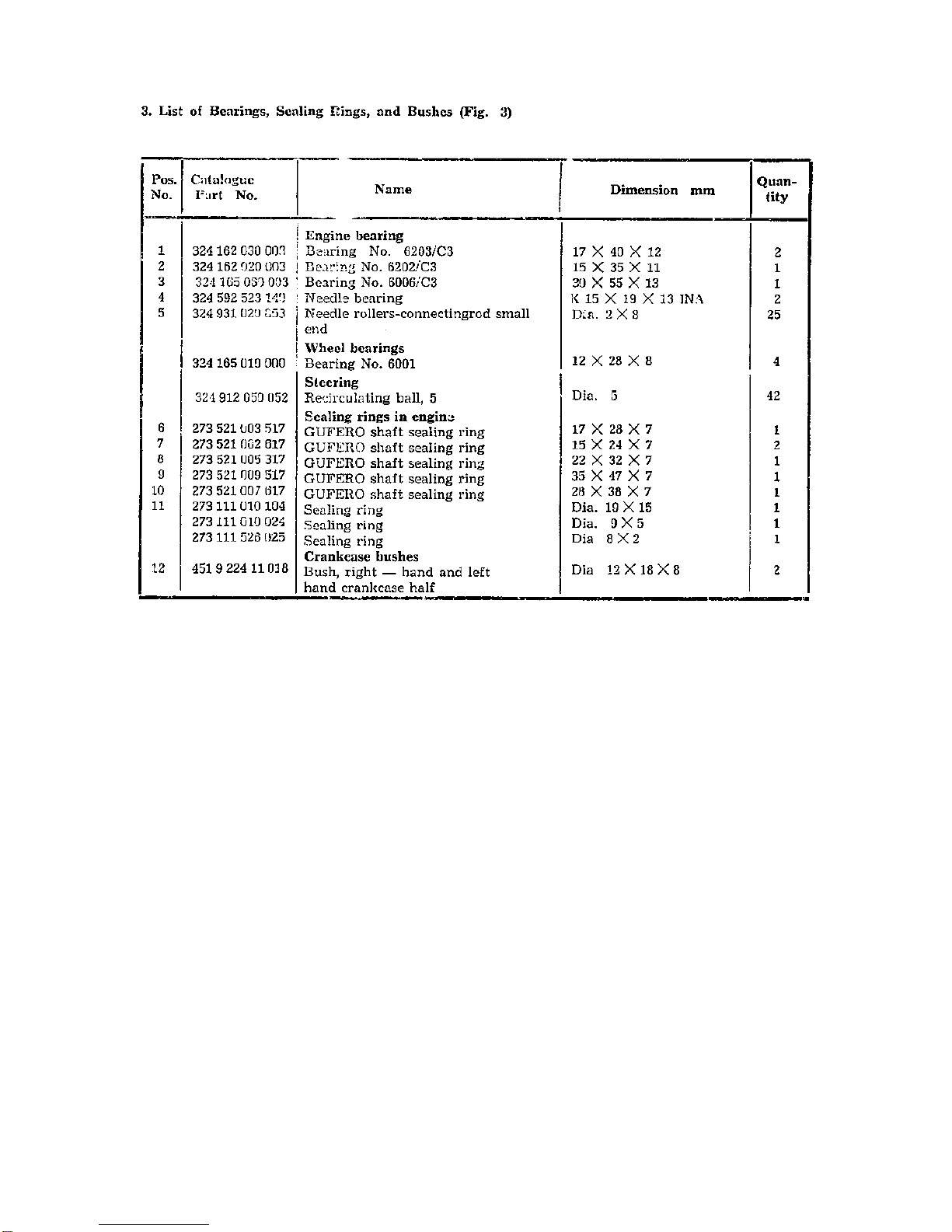
3. List of bearings, sealing rings and bushes
4. Engine torque transmission — diagram
and description
III. Engine
1. Removing engine from frame
2. Removing cylinder head, cylinder and
piston
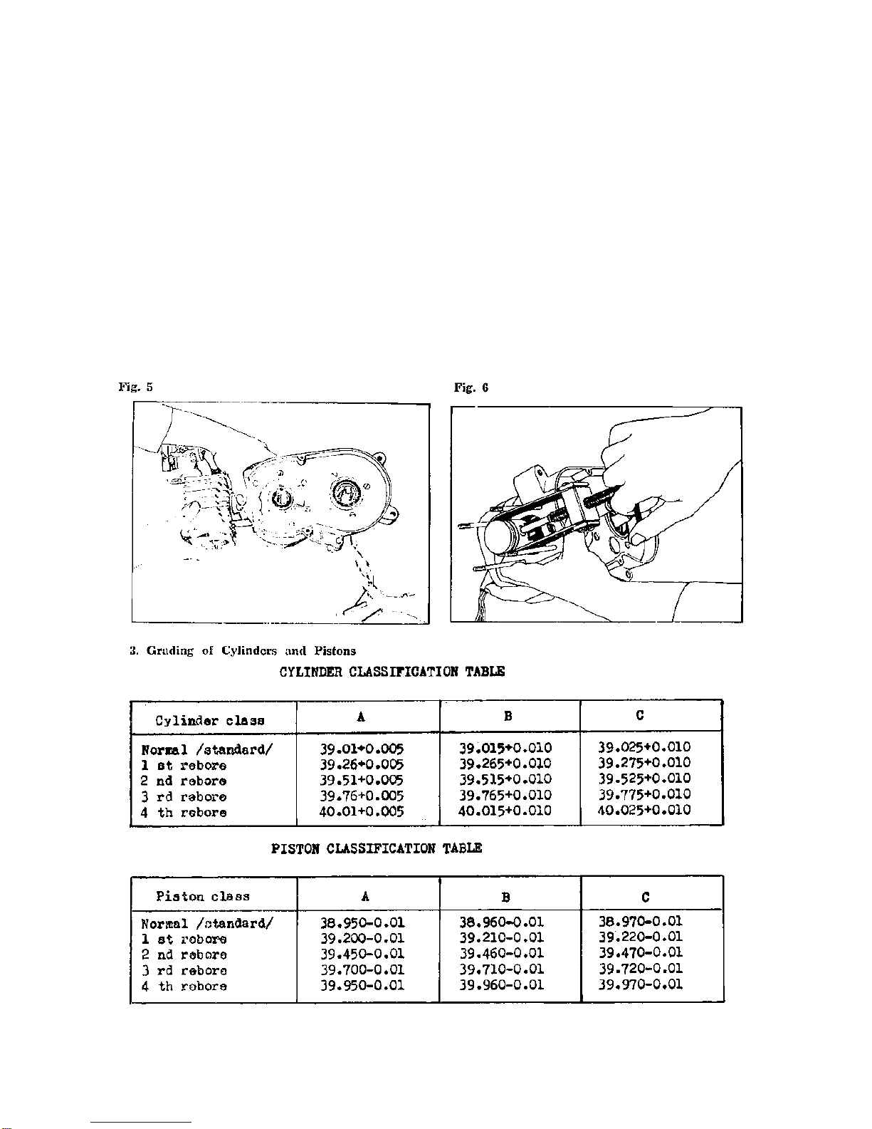
3. Grading of cylinders and pistons
4. Clutch dismantling
5. Carburettor
6. Crankshaft
IV. Frame
1. Front, telescopic fork
2. Front, and rear wheel
3. Rear wheel telescopic suspension
V. Electrical equipment
1. Alternator
2. Ignition system
3. Wiring diagram
4. Diagnosing electronic ignition defects
VI. Causes of defects and their removal
I. MOPED SPECIFICATIONS
Engine type air cooled, two-stroke single-cylinder unit
Swept volume 49 cc
Cylinder bore x piston stroke 39 x 41 mm
Engine power output 1.75 kW at 5,000 rpm ± 8 %
Clutches automatic, dry, centrifugal
Gearbox two-speed unit
Engine to rear wheel 1st. speed overall ratio --- 1 : 24.4231
transmission ratio 2nd. speed overall ratio --- 1 : 13.7305
Primary transmission indented belt
Secondary transmission link chain
Pedal drive transmission ratio1 : 0.692
Pedal-actuated starting gear overall ratio 1 : 0.0504
Front suspension telescopic fork without shock absorbers
60 mm stroke
Rear suspension telescopic suspension units without shock
Absorber -- 60 mm stroke
Brakes internal expanding shoe -- brakes controlled
by levers on handlebars
Brake dimensions 85 x 20 mm
Tyres 2¼ x 16"
Wheels 1.60” (WH1) x 16”
Inflation pressures - front tyre 196 kPa (2 atm) [ 28 psi ]
- rear tyre 245 kPa (2.5 atm.) [ 36 psi ]
Moped dry weight 51 kg
Moped running weight 54 kg
Road speed - sustained 35 km/hr.
- maximum 40 km/hr ± 5 %
Fuel tank filling capacity 4 litres
Fuel reserve 0,7 litres
Maximum climbable gradient
with rider weighing 75 kg 25 %
Noise 70 decibels
Ignition system 6 volt, contactless with semiconductor
elements
Spark plug PAL N 7 R [ Champion L89CM L85 L86 ]
[ NGK B6HS Bosh W7AC ]
Headlamp 6 v 21 w
Tail lamp 6 v 5 w
Speedometer lighting 6 v 2 w
Fuel consumption 1.8 litres/100 km at 27 km/hr
Load capacity, maximum 90 kg including 5 kg luggage on carrier
Note:
When exceeding the load capacity, it is necessary to decrease the
maximum speed proportionally
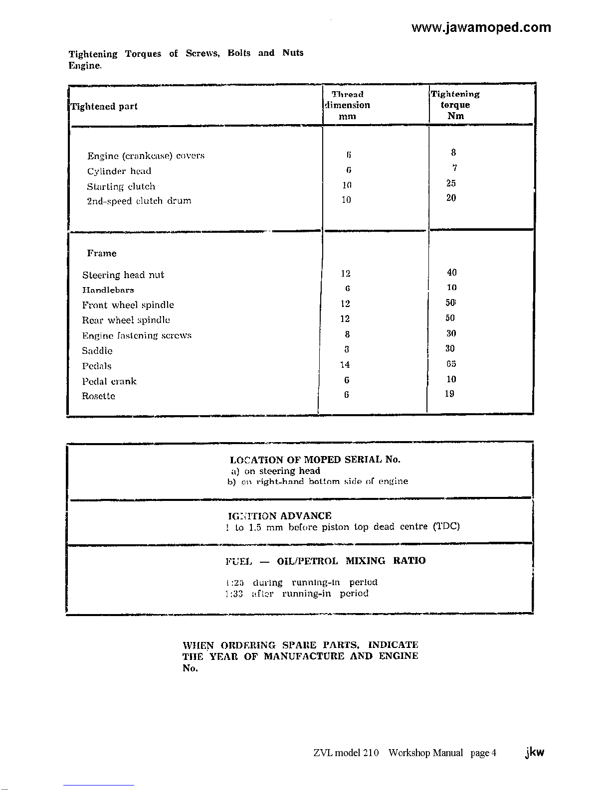
ZVL model 210 Workshop Manual Pages 1, 2 & 3 jkw


www.jawamoped.com
4. Engine Torque Transmission - Diagram (Fig. 4) (C) so that they run at the same speed. The run-
and Description ning of the layshaft gears (4) and (5) at different
speeds is enabled by the freewheel (D). The gear
Gearbox change is effected by the automatic centrifugal
The diagram of the two-speed automatic trans- clutch (C) provided with two shoes of the leading
mission is shown in Fig. 4. type. The operation of this clutch is controlled by
force closing between the parts (2'), (6) and (7)
The torque is transmitted from the crankshaft
(1) to the gears (2—2') over the starting clutch
(B) by an indented belt. From the output shaft (7), the torque is trans-
mitted to the rear wheel by means of secondary
1st-speed gearing: transmission.
It is formed by two pairs of involute spur gears
(3, 4, 5 and 6) meshing with the freewheel (D) The force-closed clutch engages the respective
between the gears (4) an(5) on the layshaft. From gear depending on the road speed, the drive taken
the gear (6), the torque is transmitted over a force off the automatic transmission, the acceleration
closed mechanism to the output shaft (7) and and deceleration, and the rolling resistance of
the rear wheel by means of the secondary trans- the vehicle in terrain
mission chain.
2nd-speed gearing: The output shaft (7) with the gear-change me-
chanism runs in two ball bearings. The layshaft
Parts (3), (6), and (7) are coupled with the clutch is supported by two bronze bushes.
ZVL model 210 Workshop Manual Page 8 jkw


www.jawamoped.com
III ENGINE
1. Removing engine from frame
a) Remove the engine guards.
b) Detach the spark plug cable, the fuel hose, and the
throttle cable.
c) Disconnect the leads of the electrical equipment.
d) Disconnect the chain of the secondary transmission.
e) Disconnect the exhaust pipe from the engine.
f) Remove screws fastening the engine to the frame,
and lift off the engine.
Clean well the surfaces of the engine, and drain the oil
from the automatic transmission case. During engine
dismantling, clean immediately all the removed parts
and put them aside in the order of their removal, so that
they can be reassembled correctly and in the shortest
possible time.
2. Removing cylinder head, cylinder and piston
a) Unscrew the four M6 nuts and lift them off together
with washers from the studs.
b) Remove the cylinder head.
c) Remove the cylinder (Fig. 5)
d) Remove the circlips securing the gudgeon pin and
use the drift No. 50-12000-1.1 (Fig. 6) to drive out
the gudgeon pin.
Take care not to spill the dia.. 2 x 8 mm needle rollers
of the gudgeon pin (there are altogether twenty five).
The maximum permissible ring gap of a worn piston
ring is from 0.6 mm to 0.8 mm.
Check the dimension for grading the pistons in the
individual classes 34.5 mm. From the piston base (Fig.
7)
ZVL model 210 Workshop Manual Page 10 jkw

www.jawamoped.com
4. Clutch Dismantling
After removing two M 5 x 30 screws, lift off the left-
hand clutch cover.
Using the clutch drum retaining jig No. 928-1000-1.5
retain the starting clutch drum and loosen the nut with
the spanner No. 17 (Fig. 8). Pull off the clutch drum
using the drag No. 4T 210-2200-01 (Fig. 9). With a
screwdriver remove three circlips from the recesses to
loosen the clutch starting shoes (Fig. 10)
For re-assembly use the washer No. 4T 210-2100 and clutch
drum drag No. 4T 210-2200-01 and secure the clutch with the
circlips (Fig. 11).
After having removed the drum with starting shoes,
rotate and gently pull the starting drum with the sma11
pulley to remove it together with the indented belt.
Work carefully so as not to damage the needle bearings
and washers.
ZVL model 210 Workshop Manual Page 11 jkw

www.jawamoped.com
For the removal and refitting of the starting shoes use
the jig (hook) No. MN 1100-7.1 (Fig. 12) or flat pliers.
Loosen the nut of the drum housing the change gear
shoes with the spanner No. 17 while holding the output
shaft with the spanner No. 10 on the side of the drive
(power take-off) gear to prevent its rotation. It is
recommended to put the engine on the work bench with
the ignition side down to prevent the oil from getting
into the 2nd-speed clutch drum.
After unscrewing the nut and lifting off the cover,
remove the circular packing piece and pull out the
change-gear shoes together with their carrier (backing
plate) using two thin screwdrivers braced against the
inner edge of the drum. Insert the tips of the
screwdrivers under the top arms of the shoe near the
pivots and opposite each other. By carefully pushing the
screwdriver handles downward you will lift the carrier
with the shoes out of the drum.
Wipe the oil off the parts immediately and put the parts
in a clean place. If the drum or the shoe linings are
stained with oil, they have to be degreased thoroughly.
Finally remove the drum of the change-gear clutch.
When removing and refitting the shoe carrier, take care
not to damage or lose the distance piece and the sealing
ring (19 x 15).
Separating crankcase halves
a) Unscrew and remove ten M6 x 45 screws from the
left-hand crankcase half.
b) Fit the jig (crankcase halves separator) No.3T 210-10
000-14.5 on the studs and fasten it by two screws on the
left-hand half of the crankcase.
c) Pull off the left-hand crankcase half (Fig. 13).
ZVL model 210 Workshop Manual Page 12 jkw

www.jawamoped.com
Removing gears
a) Removing driving gear (28 teeth) from output shaft
— see Fig. 14.
b) Removing coaster pinion — see Fig. 15.
c) Removing driven gear — see Fig. 16.
Removing driver assembly
a) Using a screwdriver, loosen the circlip and pull the
washer, the volute spring and the complete driver off the
output shaft (Fig. 17)
b) Using circlip pliers, loosen the circlip and pull the
washer, the cap, and the sprocket off the shaft (Fig. 18).
c) After loosening the circlip, press the output shaft out
of the case.
When reassembling the output shaft, use the sealing
ring installer (Fig. 19) to protect the shaft sealing rings
from damage,
Removing alternator
a) Use a screwdriver to loosen the alternator cover
retaining spring, and remove the cover Then unscrew
the M5 x 25 screw holding down the rotor.
b) Using the rotor drag No. 928-6000-1.1 pull of the
rotor (Fig. 20) and the loosen the lock pin.
c) Remove two M4 x 22 screws fastening the stator, and
pull the stator out of the crankcase right-hand half
together with the leads.
After having removed the transmission clutch and the
alternator, use a hand press to press the crankshaft out
of the crankcase.
Engine re-assembly
To re-assemble the engine, reverse the procedure for its
dismantling
a) Warm up the right-hand of the crankcase to about 70
to 80 °C and press in the crankshaft
b) Reassemble and reinstall the transmission,
c) Press on the left-hand half of the crankcase. (warmed
up to about 70 to 80°C)
d) Reassemble and reinstall the clutch.
e) Reinstall the reassembled alternator and the
assembled driver (engine drive engaging and
disengaging device)
f) Reinstall the piston, the cylinder, and the cylinder
head.
(The arrow on the piston crown points down, towards
the exhaust port.)
If any of the parts are worn beyond the acceptable
measure, replace them with new ones.
ZVL model 210 Workshop Manual Page 13 jkw

www.jawamoped.com
Reassembling 2nd-speed clutch
Observe utmost cleanliness during the clutch re-
assembly. Degrease the drum (large pulley) with a
degreasing agent (e.g. alcohol, acetone, clean petrol,
etc) and wipe it dry with a clean cloth. The roughness of
the drum working (friction) surface must be at least 0.8,
i.e. the surface must be polished with fine emery paper.
A rougher surface has an unfavourable effect on the
service life of the friction lining.
Make sure that the GUFERO sealing ring (15 x 24 x 7)
in the drum is not damaged. Put the shoe carrier (base
plate), with the two 2nd-speed shoes mounted in
position together with the regulating driver located
between them into the drum. All parts must be dry,
without any traces of oil.
If oil has got between the joint faces during the
dismantling, remove the 2nd-speed shoes and dip the
carrier in a solvent (degreasing agent). Then dry the
carrier thoroughly.
The hard chrome-plated lands of the regulating driver
which touch the brass friction layer on the shoes must
be bright, clean and dry. Rotate the shoe carrier together
with the regulating driver anticlockwise and fit the parts
in their position by a slight pressure of the hand.
Never touch the friction lining and the friction surface
of the drum with greasy hands. Place the ,’O’ sealing
ring on the recess (clean and undamaged) of the carrier
hub and locate the metal bush on the ,’O’ ring. Then
apply a tube of sufficient length and the same diameter
as the bush on the bush, and by rotating and pressing
down the tube, press the bush through the ‘O’ ring
inside the hub. Then install the inside driver which
ensures that the regulating driver controls both shoes at
the same time. For this reason, the holes must be
perfectly clean and the parts must have a certain
clearance along the circumference with the exception of
the contact areas.
Locate the circular sheet-metal washer and the clutch
cover, and then screw down and tighten well the M10 x
1.25 nut
5. Carburettor (Fig. 21)
The moped is fitted with the JIKOV 2912 DC
carburettor with the following parts and adjustments :
Main jet 63
Idling jet 35
Needle valve
- needle position 2nd notch from top
Fast-idling screw 540º (1 to 1½ turns)
Routine maintenance of the carburettor includes its
removal, flushing and swilling with clean petrol, and
blowing through with compressed air. Clean the jets
only with petrol (or acetone) and compressed air, never
with lengths of wire or other hard objects which are apt
to damage the calibrated holes.
To give the carburettor a thorough overhaul, proceed as
follows:
1. Remove the carburettor from the engine, take it apart,
and clean its parts thoroughly.
2. Discard worn parts and replace them with new ones.
3. Check the flatness of the flange and true it up if
necessary on an abrasive cloth stretched on a flat board.
4. After trueing up the flange clean the carburettor body
thoroughly once again.
5. Check the jets and adjustments for compliance with
the recommended values.
6. Adjust the needle and the fast-idling screw as
recommended and reassemble the carburettor.
7. Refit the carburettor on the engine. Start the engine,
warm it up, and adjust the richness of the mixture by
means of the air-correction screw. Then adjust the
idling speed (from 1,600 to 1,800 r.p.m.) by means of
the stop screw, and the needle valve and the free
movement of the twistgrip by means of the throttle
cable guide.
ZVL model 210 Workshop Manual Page 14 jkw

www.jawamoped.com
Checking and adjusting fuel level in float 2. Checking fuel level using the jig illustrated
chamber in Fig. 22a
Check and adjust the fuel level after every
renewal of the fuel float or if the fuel leaks from After having adjusted, the fuel level mechanically
the carburettor and the leakage is not due to a it is recommended to check the adjustment
defective float or needle. Fuel level adjusting pro- with the help of the jig which you can make
cedure:-. of plexiglass (Perspex) according to the drawing.
Screw the jig on to the float chamber (bottom
1. Rough (mechanical) adjustment -- see Fig. 22 drain screw) and admit fuel into the carburettor.
Its level should reach the centre index line with
With the carburettor removed from the engine, a tolerance of ± 1 mm. If this is not the case, ad-
remove the float chamber cover. Turn the carbu- just the floats by bending the arms upward
rettor so that the floats are directed upwards, or downward as necessary. The fuel level adjusted
Check that the floats move freely on the spindle in this way complies with the manufacturer's
and that they are perpendicular to the carburettor requirements. When checking the fuel level in the
centre line. Check also their height which must carburettor removed from the engine, it is necessary
reach the level of the venturi tube top edge. If to observe the same height of the pressure column
this is not the case, adjust the height of both floats as exists between the fuel tank and the carburettor
by bending the arms. Floats adjusted in this way fitted on the engine.
should maintain the fuel in the float chamber
at the correct level.
ZVL model 210 Workshop Manual Page 15 jkw


www.jawamoped.com
6. Crankshaft
Removal and reinstallation
1. Use a press with a pressure of about 50,000 N.
Before removing the crankshaft, mark the relative
positions of the crankshaft flywheels with index lines
using a set square.
2. Press the crankpin out of one half of the crankshaft
and then out of the other half.
3. Assemble the connecting rod, the crankpin and the
cage with needle rollers according to the classification
table.
4. Clean thoroughly all parts of the crankshaft,
especially the crankpins, which must be perfectly dry
5. Press the crankpin in the flywheel till its face is flush
with the outer surface of the flywheel.
6. Fit in position the cage with needle rollers and
lubricate the needle rollers with lubricating grease.
7. press the flywheels together – observe the previously
made index lines.
8. After reassembly, it is necessary to centre the
crankshaft.
ZVL model 210 Workshop Manual Page 17 jkw

www.jawamoped.com
Crankshaft aligning
Check the aligning and the permissible untrue run using
a special jig with centres and two dial indicators. The
crankshaft must be supported in the centres so that it can
rotate. The maximum permissible relative run-out of the
functional points is 0.016mm. The functional points in
this instance are the shoulders for the bearings. The
design of the crankshaft and the manufacturing process
guarantee this value. Check the run-out or untrue run
before installing the crankshaft in the engine.
Misalignment of the crankshaft is usually caused by a
crash, rough handling during transport, dropping the
crankshaft on the ground or by an unskilled repair. You
will obtain the correct axial (lateral) clearance of the
crankshaft in the crankcase if you maintain the
dimension 38-0.2mm (distance of the shoulders for the
bearings) when pressing the crankshaft together. The
minimum distance of the flywheels in place on the
crankpin must be 12.2mm.
Crankshaft aligning and straightening procedure
Check the alignment of crankpins as illustrated in Fig
23. If the crankshaft halves are mutually set off, remove
the crankshaft from the centres,
and using a suitable copper or aluminium pad and a
hammer of soft material work on it till the crankpins are
aligned as perfectly as possible The two crankshaft
halves are not set off if both dial indicators give the
same readings when rotating the crankshaft. If after this
procedure the mutual run-out of the functional parts is
greater than 0.016mm, straighten the crankshaft (its
axis) by bending both its halves against each other in the
required direction.
This procedure is depicted in Fig. 23. Depending on the
deflection of the crankshaft axis (ascertained by dial
indicators), bend the flywheels toward each other ( - -
readings) or away from each other (+ + readings). If
necessary, repeat the bending on more planes than the
one given in the illustration.
Decisive for the final straightening is the maximum
permissible untrue run of the functional part (surfaces)
of 0.016mm. If you fail to obtain this value by the
described procedure, it means that the crank mechanism
is defective and has to be replaced with a new one. As
this work requires great skill, it should be done by a
highly qualified fitter.
Fig. 23
ZVL model 210 Workshop Manual Page 18 jkw


Other manuals for ZVL 210
1
Table of contents
Other JAWA Motorcycle manuals

JAWA
JAWA 638 Instruction manual

JAWA
JAWA B User manual

JAWA
JAWA RVM-600 User manual

JAWA
JAWA 250 TRAVEL User manual

JAWA
JAWA 559/04 User guide

JAWA
JAWA F 350/634-5,8 User guide

JAWA
JAWA 350 Instruction manual

JAWA
JAWA 300 CL 2020 User manual

JAWA
JAWA Dandy MJ50 User manual

JAWA
JAWA 1992 350/638 Instruction manual