7
JB
INDUSTRIES
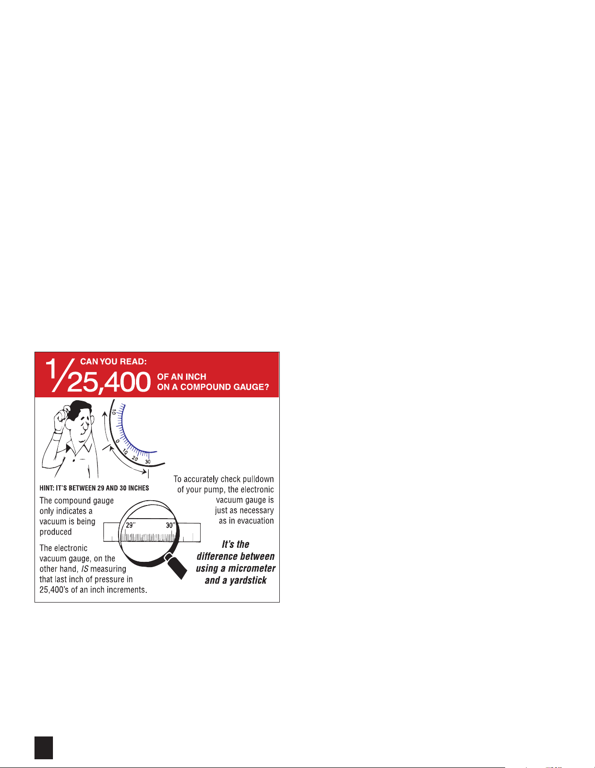
• PLATINUM OPERATING MANUAL • 800.323.0811 • [email protected] • JBIND.COMIf you are used to using a compound gauge when testing for a leak or holding a
vacuum, using a digital gauge will be a little tricky the first time you use it. JB
digital vacuum gauges will display microns jumping up and down in measure.
You might think that the gauge is erratic or that there is a leak in the system. The
reason for the changing microns is due to a whole other area of understanding the
environment inside a system being vacuumed. We will discuss this event in the
next section on Digital Micron Gauges.
To help show the difference of a digital and analog displays in microns, and a
compound gauge display in inches of mercury (inHg) as it relates to their displays
of vacuum, we need to hook them up. Take a compound gauge and a digital micron
gauge, and an empty refrigerant tank. This hook-up is illustrated on the next page
(Figure 20). This allows you to demonstrate the four components in holding a
vacuum: the connections, the volume, the depth of vacuum, and the length of time
that volume is in deep vacuum.
Link both gauges together by solid brass adapters and o-ring couplers and couple
to the tank. The tank is connected by an o-ring coupler to one of the intake ports
of the pump by way of braided metal hose with o-ring connections. Then, with
the isolation valve in the open position, we can begin to vacuum this hook-up
and watch the readings on the various gauges move into deep vacuum. Within
seconds, the compound gauge’s needle should be nearing 27-29" while the digital
and analog gauge readings are still heading into deeper microns.
After the digital gauge reaches 500-600 microns, close the isolation valve. You
will see the digital reading start a pretty rapid rise in micron readings. Notice that
the compound gauge’s needle has not moved.
NOTE: If the compound gauge’s needle does move toward zero on the scale, you
have an air leak in your connections. Open the isolation valve again and this time
let the hook-up vacuum for 5 minutes. Then close the isolation valve again and
watch. Open the isolation valve for about a minute, then move the valve to the
pause position for about 5 seconds, then close the valve completely. This removes
that trapped air around the isolation valve. You will still see a rise in pressure, but
not as rapid. The readings will start to stabilize the longer this hook-up is allowed
to vacuum down and use the pause position of the isolation valve the slower and
lower the rise in pressure.
If you increase the volume of the cylinder and follow the same procedure, you will
notice a slower and lower rise. If you watch your compound gauge, you will notice
there is no movement.
DIGITAL MICRON GAUGES
Inaccurate Readings
NOTE: For the JB digital vacuum gauges we have a stated accuracy that references
AVERAGE accuracy. Thus, between 250 and 6000 microns the unit is +/-10%
AVERAGE accuracy and between 50 to 250 microns it is +/-15% AVERAGE
accuracy. This does not mean our gauge has a large accuracy discrepancy.
The term AVERAGE is an important part of this accuracy description. The number of
increments displayed on the JB digital micron gauge between 50 and 250 microns
are 97. Between 250 microns and 6000 microns, there are 232 increments. If you
take a comparison reading between the JB digital vacuum gauges and the MKS
Baratron master gauge at each of the increments displayed on the digital micron
gauge the average accuracy would be +/-10% in one range and +/-15% the average
in the other range. Also, the number of increments decrease from the lower micron
readings to the higher micron readings.
For example, from 250 to 300 microns there are 16 increments, from 650-
700 microns there are only 7 increments, between 1000 and 1050 there are 4
increments, and between 4000 and 4500 there are 4 increments. So at 650 to
700 microns the gauge has the ability to show 650-658-667-675-680-685-690-
695. But at the micron range of 4000 to 4500, the gauge only displays 4125-
4250-4375. This is important because when the system has an actual micron
level of 4260, the digital micron gauge will show a reading of 4375 because the
threshold for the lower value that the gauge displays, 4250, has not been reached.
Once that threshold has been reached, the gauge will display that lower value of
4250. Because the readings in these higher micron ranges only need to show the
movement through them , the difference between 4375 and 4250 is of no concern
in reaching the ultimate vacuum desired. This is why the JB digital vacuum gauges
are designed with the most increments in range that are going to be the most critical
in determining if the system is ready for charging.
If you understand the size of a micron, then small differences in ranges is nothing
to be concerned about. For instance:
MICRON RANGE MICRON DIFFERENCE
60-100 10-20
200-350 30-40
500-700 50-60
900-1500 80-100
2500-4000 200-300
When a JB digital vacuum gauge comes in for repair, it is compared to a secured
system set up with a N.I.S.T. traceable master gauge. Usually starting around
(1) 60-100 microns, then (2)200-350 microns, then (3)500-700 microns, then
(4) 900-1000 microns. These ranges of vacuum are the most common that people
work with to determine deep vacuum.
Figure 20