JBF DIP 500 User manual

JBF DIP 500
SKIMMING SYSTEM
OPERATION AND MAINTENANCE MANUAL
August 2001
JBF and DIP are trademarks Licensed to SLICKBAR PRODUCTS CO.

PREFACE
This manual contains comprehensive description of the JBF DIP 500 Oil and
Debris VOSS Skimming System and instructions for efficient operation and
maintenance.
Manufacturers manuals for the various components are included.

JBF Environmental Technology
1
1 CHAPTER I - INTRODUCTION..........................................................................................3
A JBF DIP 500 SKIMMING SYSTEM .................................................................................3
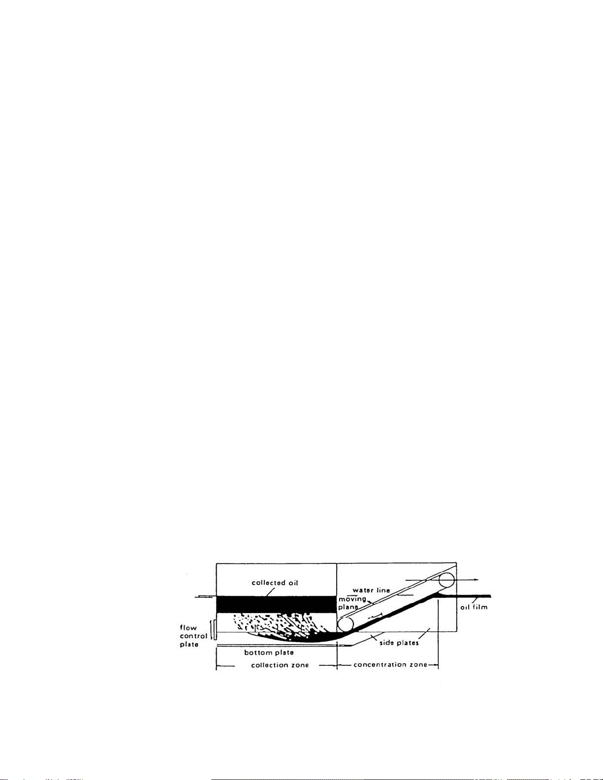
i) Explanation of the skimmer / DIP principle...................................................................3
ii) JBF DIP concept..........................................................................................................3
iii) IN-LINE ADVANCING SKIMMER-SWEEPING-FSB....................................................4
iv) SELECTION OF THE DIP 500.....................................................................................6
v) INTERFACE WITH PUMPS AND HYDRAULIC POWER UNITS.................................6
vi) OIL RECOVERY PERFORMANCE .............................................................................6
2 SYSTEM DESCRIPTION AND CHARACTERISTICS........................................................7
A GENERAL DESCRIPTION..............................................................................................7
B OPERATING CONCEPT AND LIMITS............................................................................9
i) Transportation & Storage:............................................................................................9
ii) Deployment time & Configurations:..............................................................................9
iii) Oil Recovery: ...............................................................................................................9
iv) Speed limitations:.........................................................................................................9
v) Sea state limitations...................................................................................................10
vi) Debris handling..........................................................................................................10
C MAJOR COMPONENTS ...............................................................................................10
i) Moving plane assembly..............................................................................................10
ii) Belt Motor...................................................................................................................11
iii) Collection Well...........................................................................................................11
iv) Oil Transfer Pumps....................................................................................................11
v) Pontoons....................................................................................................................11
vi) Control Stand.............................................................................................................11
vii) Transition booms .......................................................................................................12
viii) Debris Rakes .............................................................................................................12
ix) Belt Wiper ..................................................................................................................12
D COMPONENT DESCRIPTION AND CHARACTERISTICS...........................................12
i) The Hand winch.........................................................................................................12
ii) DOP 250 pump..........................................................................................................13
3 STORAGE AND TRANSPORT ........................................................................................13
A Storage..........................................................................................................................13
B Transportation ...............................................................................................................13
4 ASSEMBLY AND DEPLOYMENT....................................................................................13
A DIP 500 ASSEMBLY .....................................................................................................13
i) Assemble DIP 500 Unit..............................................................................................13
ii) Assemble Outrigger Arm............................................................................................15
iii) Deployment of DIP 500 .............................................................................................15
5 SKIMMING OPERATIONS...............................................................................................16
A PREPARATIONS FOR SKIMMING...............................................................................16
i) Operation...................................................................................................................16
ii) Connect applicable boom system and rigging............................................................17
iii) Hydraulic control stand ..............................................................................................17
B OPERATION OF MOVING PLAN ASSEMBLY ............................................................18
i) Running the belt.........................................................................................................18
ii) If the DIP belt becomes jammed or stops running. ....................................................18

JBF Environmental Technology
2
6 RETRIEVAL & LAYUP.....................................................................................................19
A Retrieval of the DIP 500. ...............................................................................................19
B Disassembly of the DIP 500 ..........................................................................................19
C Lay-up of DIP 500..........................................................................................................20
7 TROUBLESHOOTING & REPAIR....................................................................................20
A GENERAL .....................................................................................................................20
B Installation and Removal Belt Box Assembly.................................................................20
i) Remove the belt hydraulic motor as follows: ( See Figure 10 )..................................20
ii) Remove the belt assembly and box structure as follows: ..........................................21
C Belt Removal.................................................................................................................21
D Head Shaft Removal .....................................................................................................22
E Tail Shaft Removal........................................................................................................22
F Removing the cargo pumps...........................................................................................23
G Installing the cargo pumps.............................................................................................22
8 PREVENTIVE MAINTENANCE & ADJUSTMENTS.........................................................23
A BELT WIPER.................................................................................................................23
B CARGO PUMPS............................................................................................................23
C Belt Adjustment/Maintenance........................................................................................24
i) To adjust the tension on the belt use the following procedure: ..................................24
9 APPENDICIES..................................................................................................................24
A SPARE/REPAIR PARTS LIST.......................................................................................25
LIST OF TABLES
Table 1 SPECIFICATIONS................................................. 8
Table 2 PERFORMANCE SPECIFICATIONS ................................... 8
LIST OF FIGURES
Figure 2 DIP VOSS 500 SKIMMER WITH TRANSITION BOOM..................... 5

JBF Environmental Technology
3
1 CHAPTER I - INTRODUCTION
A JBF DIP 500 SKIMMING SYSTEM
i) Explanation of the skimmer / DIP principle
(1) The JBF Dynamic Inclined Plane DIP 500 Oil and Debris Recovery Skimmer
System is designed to harvest oil and debris from the surface of the water,
separate out the water and pump the harvested products directly from the
collection well into oil storage. The skimmer is equipped with a hydraulically
driven moving plane and one or two cargo pumps.
ii) JBF DIP concept
(1) The system is based on the concept of collecting oil and debris beneath the
surface of the water, thus reducing the effects of waves. As the system
moves through the water, oil and debris is forced to follow the surface of a
moving inclined plane into a collection well within the unit. Buoyant forces
cause the oil and debris to surface in the well, forcing water out the bottom.
When a sufficiently thick layer of oil has collected, the oil is pumped into a
storage tank. Large debris is removed manually from the front of the
skimmerand thecollection well. Separation occurs naturally and virtually no
free water is collected.

JBF Environmental Technology
4
iii) IN-LINE ADVANCING SKIMMER
(1) The DIP 500 skimming system is designed to be operated with a ship
(commercial leased vessel 60 to 400 feet long), turning it into an efficient oil
recovery platform. The vessel must only be capable of operating at speeds
from 1 to 3 knots during oil spill recovery operations. The vessel may also
operate at speeds up to 6 knots for transiting and maneuvering with the DIP
500 fully deployed. One or two DIP 500 units can be used by deploying
them on the port and starboard sides of the vessel.
(2) When using inflatable booms, two ends of the booms with their standard
connectors are attached to the Transition Booms of the DIP 500 which is
equipped with a tension chain to hold the aperture to 8 feet. As the vessel
moves forward the outrigger arm (28 and 42 foot are available) holds the
forward ends of the sweeping boom in a “V” geometry. The mooring lines
hold the DIP 500 from the side of the vessel. These configurations can be
towed at relative speeds between 1 and 4 knots up to sea state 4.

JBF Environmental Technology
This drawing is a sample of what the system should look like when it is deployed.
Actual lengths and sizes of boom and outriggers will vary.
5

JBF Environmental Technology
6
Figure 1 DIP 500/ BOOM CONFIGURATION
iv) SELECTION OF THE DIP 500
(1) The DIP 500 was chosen by the State of Maine because of the increased
speed (3 knots for oil recovery and 6 knotsfortransiting along sidethe vessel
of opportunity). Oil recovery tests at OHMSETT and first article tests
confirmed these additional capabilities. It is well known that realistic oil
recovery must operate at 3 knots or faster in order to maintain the vessel’s
headway and to maneuver in a typical sea state 3. It is also desirable to
transit alongside at higher speeds and sea states while heading for well
dispersed oil slicks
v) INTERFACE WITH PUMPS AND HYDRAULIC POWER UNITS
(1) The DIP 500 is designed to operate on DOP 250 pump. These pumps are
mounted on their own mounting plates which are bolted on to a common
fixed plate in the collection well of the skimmer. Safety grates are installed
on both sides of the fixed plate for easy accessibility for each installation.
The pumps are then controlled by control stands powered by HPUs.
vi) OIL RECOVERY PERFORMANCE
(1) The operator stationed at the hydraulic control stand decides how to set the
belt speed and pumping rates to obtain the optimum method of recovering
oil in a given situation.
(2) If there is a limited amount of storage available, the operator should tell the
vessel’sCaptainto operate thevessel at itsminimum speed (2knots or less).
This allows the skimmer operator to make sure that he has a full collection
well before pumping to storage and to operate the pumps at a rate as close
to the collection (intercept) rate as possible. This is accomplished by
matching the skimmer’s belt speed to the speed of the vessel and pump

JBF Environmental Technology
7
rates to the estimated operation results in a relatively slow recovery rate but
maintain a high oil recovery efficiency and a high throughput efficiency.
(3) If there is ample storage in the form of towed bladders or towed barges, the
operator should tell the Captain to operate the vessel at a high oil recovery
speed(2 to 4 knots). Normally, this isthe casewhere theoil spillis largeand
calls for the fastest possible oil recovery rate. The operator matches the belt
speed to the vessel speed and the pumps are operated at a rate as close to
the interceptrate as possibleby adjusting thehydraulicflow control valveson
the control stand.
(4) When operatinginthe 1.1.6.2 mode above theoperatormay notice oillosses
flowing out the rear of theskimmer. Do not be alarmedby these losses since
they are small relative to the amount of oil that is intercepted and collected
which results in the maximum amount of total oil recovered over time.
2 SYSTEM DESCRIPTION AND CHARACTERISTICS
A GENERAL DESCRIPTION
The DIP 500 DEPLOYMENT PACKAGE is an in-line advancing skimmer
system designed to recover oil at speeds from 1.5 to 3 knots in seas up to 3
feet. It consists of a hull with attached fender flotation, moving plane assembly
and one cargo pump. It is designed for use alongsidevesselsof opportunity,in
lakes, rivers, inner harbors and off shore. It can be transported quickly to oil
spill sites and can be used in both stationary and dynamic skimming modes.
The unit is supplied with an on board oil handling pump, transition booms and
connectors that increase the aperture from 4’to 8’. Standard boom can be
attached to the transition booms and rigging to further increase the aperture.
(See Figure 2.)
The complete system consists of one DIP 500 unit that is operated through its
own hydraulic control panel which controls the hydraulic power to the moving
plane assemblies and the DOP 250 pumps.
The module is constructed of two longitudinal bulkheads with an oil pump
compartment and forward compartment. Theseform theforwardtunnel forthe
moving plane and aft collection well.

JBF Environmental Technology
8
The hull is constructed of .25 thick 5052 aluminum alloy with aluminum tube
stiffeners. The fender/floatation system is attached to the sides of the module.
Themodule haslift slingpoints weldedto the longitudinalbulkheadsalong with
oil boom connection points located on the forward rigging.
The DIP 500 System is supplied with 4 inflatable fenders that provide primary
floatation to the unit. (FIGURE 3.)
Table 1 SPECIFICATIONS
DIP 500 SKIMMER
FULLY DEPLOYED READY FOR STORAGE
Length 15 ft 7 in 15 ft 7 in
Beam 7 ft 7 ft
Draft 4 ft in
Freeboard 2 ft 4.5in
Displacement 5500 lbs 6000 lbs
MOVING PLANE ASSEMBLY OIL TRANSFER PUMP
Belt Material: Reinforced PVC w/ SS chain Pump: 'DESMI' Screw Pump
Belt Width: 3 ft 0 in Model: DOP 250/A-02
Belt Drive: 10 cu. In. hydraulic motor Capacity: 440 gpm
Table 2 PERFORMANCE SPECIFICATIONS
Skimming Velocity: 0 to 3.5 knots
Wave Height: 3 ft Swells; 3 ft Short Crest Waves
Collection Well Volume: 375 gal (U.S.)

JBF Environmental Technology
9
OPERATING CONCEPT AND LIMITS
i) Transportation & Storage
The DIP 500 can be transported over land using a truck and flatbed
trailer capable of hauling 6000 lb, air transport or an ocean going vessel
with deck space of 8 feet by 16 feet to the scene. The units have 4
stacking pins located in each topside corner that match 4 holes located
in the 4 corner feet of the unit so that they can securely be stacked 2
high during storage. The unit has fork lift slots and lifting bridles for
loading and deploying operations.
ii) Deployment time & Configurations
The DIP 500 can be easily transported to the scene at top transit speed.
Using 4 people the unit can be assembled and deployed in less than 50
minutes from the deck of the support vessel
iii) Oil Recovery
The DIP 500 is capable of recovering oil at speeds from1 to 3.5 knots
with extremely highthroughput efficiencies. The DIP500doesn’t require
thicklayers ofoil incontained pools,in orderto be efficient. TheDIP500
operates equally well in thin slicks and thick oil and in light refined
products or high viscosity oils.
iv) Speed limitations
Trials were conducted with the DIP 500. The unit was towed with boom
connected at 3 knots in sea state 1 conditions with winds up to 7 knots
for 4 minutes. No damage occurred to the unit. The unit is capable of

JBF Environmental Technology
10
operating at 3 knots with the fast sweep boom in place.
v) Sea state limitations
Seastate limitations fortowingthe DIP500without any boomattached is
4.( It is not recommended to tow in sea state 4 for long periods of time.)
Efficient skimming conditions with boom can be achieved at sea state 1
to 1.5.
vi) Debris handling
A debris rake is installed on the front of the DIP 500 to prevent large
debris from entering the unit. Accumulated debris will have to be
removed manually. The vessel may be able to back down and free the
debris from the mouth of the boom configuration and maneuver around
the debris. Smaller debris passing throughhedebris rake will beground
up by the cutter knives in the DESMI pump and pumped to the holding
tank. Larger pieces of debris that the pump can’t handle will float to the
top of the collection well and will have to be removed manually and
placed in a suitable container.
B MAJOR COMPONENTS
i) Moving plane assembly
The moving plane assembly consists of an aluminum frame supporting two
rollers over which the collection belt is carried. The assembly mounts in the
front of the unit. The belt is a heavy-duty material made of reinforced PVC. In
order to achieve a positive drive and to avoid any possibility of slipping and
poor tracking, special SS roller chains are attached to the edge of the belt.
These chains engage sprockets on the head and tail rollers through which the
belt is driven. The tension and drive loads are taken directly by the roller
chains, while loads on the belt are only those associated with its own inertia
and motion through the water. Oil and debris being collected is held against
the belt by a combination of dynamic,buoyant,and cohesiveforcesas it moves
downward and aft into the collection well.

JBF Environmental Technology
11
ii) Belt Motor
The belt is driven by a low-speed, high-torque, 10 cu. In. hydraulic motor
through a direct drive.
iii) Collection Well
The collection well is located in the aft of the DIP 500 and is made from .25
thick 5052 aluminum alloy. The well has a capacity of 375 gal. (US).
iv) Oil Transfer Pumps
Installed in the aft compartment of the DIP 500 (Above the collection well) is a
DESMI DOP250 oil transfer pump. The pump is used to transfer harvested oil
and debris from the collection well to the on-board tanks or to auxiliary holding
tanks alongside. The compartment is designedto accommodate 1pump. The
pumpshould runin the'forward' direction. Themaximum hydraulicinputtothe
DOP 250 pump is 42 gpm. Pump speed is controlled by varying the position of
the speed control knob from 0 to full flow.
v) Pontoons
TheDIP 500is suppliedwith 4inflatable fenders that provideprimaryfloatation
to the unit. The fenders are inflatable, each has 1 air chamber. Bladders are
constructed of urethane which provides a tough abrasion resistant surface.
The fenders are installed on the side and under a protruding lip with a series of
shackles. The fender/floatation construction hasthe advantageof light-weight
construction and the ability to reduce the size of the unit for shipping.
vi) Control Stand
The purpose of the control stand is to operate all hydraulic motors and pumps
and enable the State of Maine to use their existing HPU units withthe DIP500.

JBF Environmental Technology
12
The control stand ensures operational compatibility between the HPUs, the
DIP 500 and the pump. It should be where the operator has a clear view of the
skimmer and the apex of the boom configuration used.
vii) Transition booms
Thetransitionbooms are inflatableandhave standardASTMboom connectors
on each end and are equipped with a tension chain to hold the aperture to 8
feet.
viii) Debris Rakes
There are 4 rods evenly spaced in front of the skimmer mouth. The rods
prevent large debris from entering the mouth of the skimmer. They also are
used to lock the storage in place.
\
ix) Belt Wiper
The wiper is mounted in the collection well and is fabricatedof reinforced PVC.
Its primary function is to insure that collected oil is removed from the belt. Its
secondary function is to prevent debris fromlodging between the bottom of the
forward compartment and the top of the belt.
CAUTION
Adjust wiper position to insure no undue pressure is on the belt.
C COMPONENT DESCRIPTION AND CHARACTERISTICS
i) Hand winch
The winch is a hand operated come-along style. The winch is used to lower
andlift themovingplane assemblyinto placeduring disassembly and assembly
.

JBF Environmental Technology
13
DOP 250 pump
The DESMI pump is used to pump collected oil from the collection well to the
storage tanks. It should run in the 'forward' direction as indicated at the
directional control valve located on the control panel. The maximum hydraulic
input to the pump is 42 gpm, which is set at the flow control valve. Pump
speed is controlled by varying the position of the directional control valve
handle from 0 to full flow. Operate the pump in reverse for 5-10 seconds to
clear the piping and pump before terminating skimming operations and to
prevent water from freezing in the pump cavity.
3 STORAGE AND TRANSPORT
A Storage
The DIP 500 can be stored inside a building, outside in a secure area, on the deck
of a sea going vessel or in the cargo hull compartment of the vessel. The units
have a protective cover. The units have 4 stacking pins located in each topside
corner that match 4 holes located in the 4 corner feet of the unit so that they can
securely be stacked 2 high during storage.
B Transportation
The DIP 500 can be transported over land using a truck and flatbed trailer capable
ofhauling 6000lb, militaryair transportor an ocean going vessel withdeck spaceof
8 feet by 16 feet to the scene. The unit has fork lift slots and lifting bridles for
loading and deploying operations.
4 ASSEMBLY AND DEPLOYMENT
A DIP 500 ASSEMBLY
i) Assemble DIP 500 Unit
(1) Remove the cover from the skimmer

JBF Environmental Technology
14
(2) Remove equipment from storage bin.
(a) Remove all other equipment and sort out on deck.
(b) Take control stand out.
(3) Remove the upper safety grate from the oil collection well / pump
compartment.
(a) Loosen the locking dog bolts in each corner.
(b) Using 2 people lift the grate up and lower over the end to 2 people on the
deck.
(c) Stow in storage.
(4) Inflate the pontoons.
(a) Remove the cover from the pontoon valves.
(b) Make sure the valve is closed by turning the valve ¼ turn counter
clockwise.
(c) Use the air pump with the special adapter inflate pontoons to 2 psi.
(d) Replace the valve caps.
(5) Connect the transition boom.
(a) Unroll the boom making sure the boom is right side up.
(b) Place one person on top of the skimmer and one on the ground.
(c) Hand the boom-connector to the person on top.
(d) The person on top slides the ASTM boom-connector into the ASTM
boom-connector on the front of the skimmer having the person on the
ground help by guiding it into the channel.
(e) Align the pin connector holes and lock in place with the connector pin.
(f) Inflate boom until firm. (2 psi )
(g) Repeat steps 3 through 7 for the other side.
(6) Install the pump. (If not already installed)
(a) Install the safety grates on both sides of the collection well.
(b) To install the cargo pump, lift the pump with the lifting slings over to the

JBF Environmental Technology
15
collection well area.
(c) Align the pump mounting frame with the 4 holes in the pump chamber.
(d) Install the 4 bolts and tighten using the 4 Nylock nuts.
(e) Remove the lifting slings.
(f) Clean the 3 hydraulic fitting on the lines and the pump.
(g) Connect the required length of 1” supply lines (2each) to the pumps and
the other ends to the control panel.
(h) Connect the required length of ½” case drain line to the pump and the
other end to the control panel.
(i) Connect the oil discharge hose to the pumps..
(j) Remove the safety grates and stow in storage.
(7) Connect hydraulic motor supply lines.
(a) Clean all hydraulic fitting on the lines and connection plate.
(b) Connect the two short ½” supply lines to the motor.
(c) Connect the required length of ½”supply linesto eachof thefittings(2) on
the top inside of the collection well.
(d) Connect the other ends of the supply lines to the control panel.
(e) See figure 22 for hydraulic connectors on control panel.
ii) Assemble Outrigger Arm
(1) The DIP 500 VOSS utilizes a deflection boom collection system which is
unique in the way that it is configured and deployed. The assembly
procedures are as follows place all the arm rigging on deck. The flotation
bouy should be on the outside and the mounting plate on the inside.
Assemble with the provided hardware and secure to side of vessel, with the
flotation bouy on the outside of the system
Iii Deployment of DIP 500 .
(2) The design of the DIP 500 VOSS enables it to be deployed with or without
theside sweeping containmentboomand 15 footoutrigger arm (See manual
for boom and outrigger arm deployment) The skimmer is deployed as

JBF Environmental Technology
16
follows:
(a) Remove two ½” mooring lines from storage box.
(b) Connect slings to the 4 lift points at each corner of the DIP 500 skimmer
using 4 shackles.
(c) Securer 2 mooring lines (from the storage box) to the inboard side of the
skimmer one forward and aft.
(d) Attach the crane hook to the DIP 500 lifting slings. Remove the deck
lashing from the unit and have at least two individuals on deck for
spotters and line handlers for deploying the skimmer. (use mooring line
for tag line)
(e) Lash all hydraulic anddischarge linesin a neatmannerto the centercleat
on the DIP 500.
(f) From the point that the lines are attached to the center cleat measure out
about 10 or 12 feet and lash the lines together again making a loop in the
line capable of accommodating the on board crane hook.
(g) Attach a short tag line to the lifting ring of the DIP 500 lifting sling
assembly so that it can be secured to a deck cleat next to the skimmer.
(h) Lift and deploy the skimmer alongside the vessel and secure.
(i) OperatetheDOP pump (See 4.3.1) andobservethe discharge fromthe 4
inch hose. The discharge hose can now be connected to the storage
tank connection.
(j) Disconnect the crane hook from the lifting ring and connect it to the
lashed hoses.
(k) Adjust crane to hold lines so that they don’t interfere with the skimmer
beingtowed evenlyand donot interferewith the containmentboom being
used.
5 SKIMMING OPERATIONS
A PREPARATIONS FOR SKIMMING
The steps to be taken for operating the DIP 500 units are as follows.
i) Operation

JBF Environmental Technology
17
To operate the pump, connect the hose between the pump discharge
connection on the VOSS and to the cargo tanks or the overboard tank.
Perform the following procedures:
(1) Activate the hydraulic power system.
(2) Open the valve to the cargo tank.
(3) Stationa lookoutat the cargotanksor overboard tank. Monitorthe discharge
and the tank level gauges.
(4) Operate the pumphydraulic directional controlvalve in "FORWARD"topump
from the collection well.
(5) Operate the pump hydraulic valve in "REVERSE" to clear the hoses, pump
and to clear debris blocking the pump intake.
NOTE
Whenpumping heavy,viscous oils, operatethe pump slowly toachieve a steadystream of
oil at the discharge of the hose. Gradually increase the speed of the pump while
maintaining a steady flow of oil and hold at that speed for maximum transfer rate. Speed
adjustment can be made at the Parker flow control and also by throttling the directional
control valve actuator handle.
CAUTION DO NOT DEAD HEAD DISCHARGE LINE
ii) Connect applicable boom system and rigging.
(1) Connect the selected boom to the transition boom ASTM boom-connector.
iii) Hydraulic control stand
(1) Position a person at the hydraulic control stand to operate the DIP moving
plane and the pump.
(2) The control stand consists of 2 lever controls on the top flat face of the unit
labeled;
(3) BELT (forward - neutral - reverse),
(4) PUMP (forward –neutral – reverse),
(5) The tuning knobs in front of the levers control the hydraulic flow to each
component.

JBF Environmental Technology
18
(6) A pressure gage is located on the angled face of the front panel ..
(7) The flow rate of the belt is observed through the P.S.I. gage.
(8) The flow rates for the pump is also observed through the P.S.I. gage.
(9) The connections for the power supplies and case drain are located on the
lower left-hand side of the control stand.
(a) The connections for PUMP and BELT motors are also located on the
lower back of the control stand.
(10) After the hoses are securely attached and the system is launched, open
the pressure and return lines to the panel.
(11) Check that the hydraulic directional control valves are in the neutral
position.
(12) Check that the control panel gage is indicating pressure (2000-2500psi).
(13) During skimming operations keep the belt running.
(14) Ship should advance at 1 to 3 knots depending on sea conditions.
CAUTION
The ½ inch case drain hose must be attached at all timers from the off loading pump to
the case drain fitting on the control panel and from the control panel to the power pack.
Failure to do so will result in damage to the pump and flow gages.
B OPERATION OF MOVING PLAN ASSEMBLY
i) Running the belt
(1) The DIP assembly (moving plane) should be running in both the stationary
and active skimming modes. Operate the belt at approximately 2-4 feet per
second which equates 1.2 to 2.4 knots. The speed can be set by adjusting
the hydraulic flow control. MAXIMUM setting for the belt speed should not
exceed 6 feet per second. The belt length is 23 feet so it will take 23
seconds for 1 revolutions of the belt to havea belt speed of 1fps, 16 seconds
for 1 revolutions of the belt to have a belt speed of 2 fps and12 seconds for 1
revolutions of the belt to have a belt speed of 3 fts.
ii) If the DIP belt becomes jammed or stops running.
Table of contents
Popular Swimming Pool Filter manuals by other brands

Pahlen
Pahlen 112972 user manual

Astral Pool
Astral Pool KEOPS Instruction and maintenance manual

Aqua Medic
Aqua Medic aCone 1.5 EVO Operation manual

Aqua Guard
Aqua Guard 59725 Series owner's manual

Pentair Pool Products
Pentair Pool Products SMBW 4000 Series operating manual

AquaTools
AquaTools AT8230 owner's manual

Aussie Chlorinators
Aussie Chlorinators XTreme XT15 manual

Jandy
Jandy DEL Series Installation and operation manual

ProMinent
ProMinent DULCODOS Assembly and operating instructions

Hayward
Hayward Pro Series Plus owner's manual

Beckett
Beckett FL200 Product features

Aquatic
Aquatic ALGAE SKIMMER quick start guide