JBL DA850 User manual

Owners Manual
Rev 1.2 | Draft20231009
©2023 Harman International | Features, Specifications, and Appearance subject to change without notice.
DA850
DA1650
Distribution Amplifiers

JBL DA850 DA1650 Owners Manual | rev1.2 Draft20231009 Pg 2 of 16
©2023 Harman International | Features, Specifications, and Appearance subject to change without notice.
Table of Contents
Introduction..................................................................................................................................................... 3
What’s in the Box ........................................................................................................................................ 3
Front Panel Overview ..................................................................................................................................... 4
Rear Panel Overview...................................................................................................................................... 5
Installation....................................................................................................................................................... 6
Rack Mounting ............................................................................................................................................ 6
Surface Mounting ........................................................................................................................................ 7
Hardware Setup.............................................................................................................................................. 8
Connecting Audio Inputs ............................................................................................................................. 8
Wiring Output Connnectors......................................................................................................................... 8
Connecting The AC Power Cord............................................................................................................... 10
Setting Power Mode ..................................................................................................................................... 11
Output Level Controls ................................................................................................................................... 12
Adjusting Output Levels and Clip Indication.............................................................................................. 12
LED Status.................................................................................................................................................... 12
Power LED ................................................................................................................................................ 12
Zone Status LED....................................................................................................................................... 12
Specifications................................................................................................................................................ 13
DA850 ....................................................................................................................................................... 13
DA1650 ..................................................................................................................................................... 14
Troubleshooting and Maintenance ............................................................................................................... 15
Troubleshooting ........................................................................................................................................ 15
Maintenance.............................................................................................................................................. 15

JBL DA850 DA1650 Owners Manual | rev1.2 Draft20231009 Pg 3 of 16
©2023 Harman International | Features, Specifications, and Appearance subject to change without notice.
Introduction
Thank you for purchasing a JBL DA series distribution amplifier. The DA850 and DA1650 amplifiers are
designed, engineered, and manufactured to the industry’s highest quality standards and offer system
integrators with the core features and fundamental connectivity for home audio distribution.
Please take the time to study the owner’s manual so that you can obtain the best possible service from your
amplifier at http://www.jbl.com/specialty-audio/
What’s in the Box
1. JBL DA series amplifier
2. Quick-start guide and safety sheet
3. Phoenix block connectors
4. Removable feet and fastening screws
5. Rackmount brackets and fastening screws
6. Power cord

JBL DA850 DA1650 Owners Manual | rev1.2 Draft20231009
Pg 4 of 16
©2023 Harman International | Features, Specifications, and Appearance subject to change without notice.
Front Panel Overview
1 CHANNEL STATUS LED INDICATORS
These LEDs indicate the status of each of the amplifier
channel pairs when active.
When a channel is active, its LED indicator will glow WHITE. If
the channel is in standby, the LED will be off. If clipping is
present while playing an input source, the LED will flash
YELLOW. If a channel has a fault, the LED will blink RED
indicating the presence of a short or some other problem
related to that channel pair.
2 STANDBY BUTTON
Activates and deactivates standby mode when the amplifier is
connected to AC power.
When the amplifier is connected to AC power, the standby
button LED will glow dim BLUE indicating that the unit is in
standby mode. In this state, the power amplifier section is not
activated and the unit consumes minimal AC power. Pressing
the standby button from this state will activate the power
amplifier section and the standby button LED will glow WHITE
indicating that the amplifier is powered on.
NOTE: If the trigger input is used, it will override the standby
button operation

JBL DA850 DA1650 Owners Manual | rev1.2 Draft20231009
Pg 5 of 16
©2023 Harman International | Features, Specifications, and Appearance subject to change without notice.
Rear Panel Overview
1 AC POWER INLET AND SWITCH
Connect the included AC power
cord to this standard 15A, IEC
type inlet. Supported mains
voltage range is 100-240V~.
AC power switch disconnects amplifier
completely from AC mains.
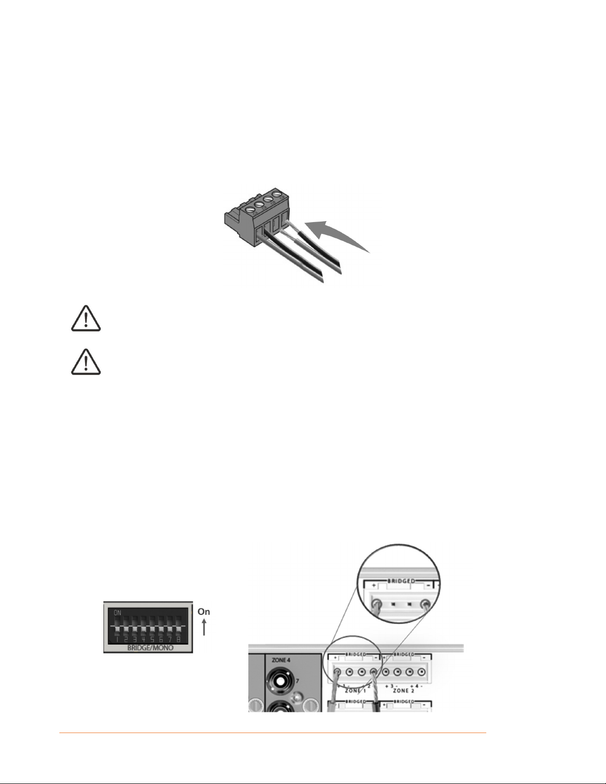
2 BRIDGE/MONO MODE
Set the switch to the UP position per
zone to enable Bridge/Mono Mode.
When Bridge/Mono is enabled for a
zone, the Left and Right inputs are
summed to mono.
In Bridge/Mono mode, outputs can be
used in either Bridge outputs or single
channel pairs.
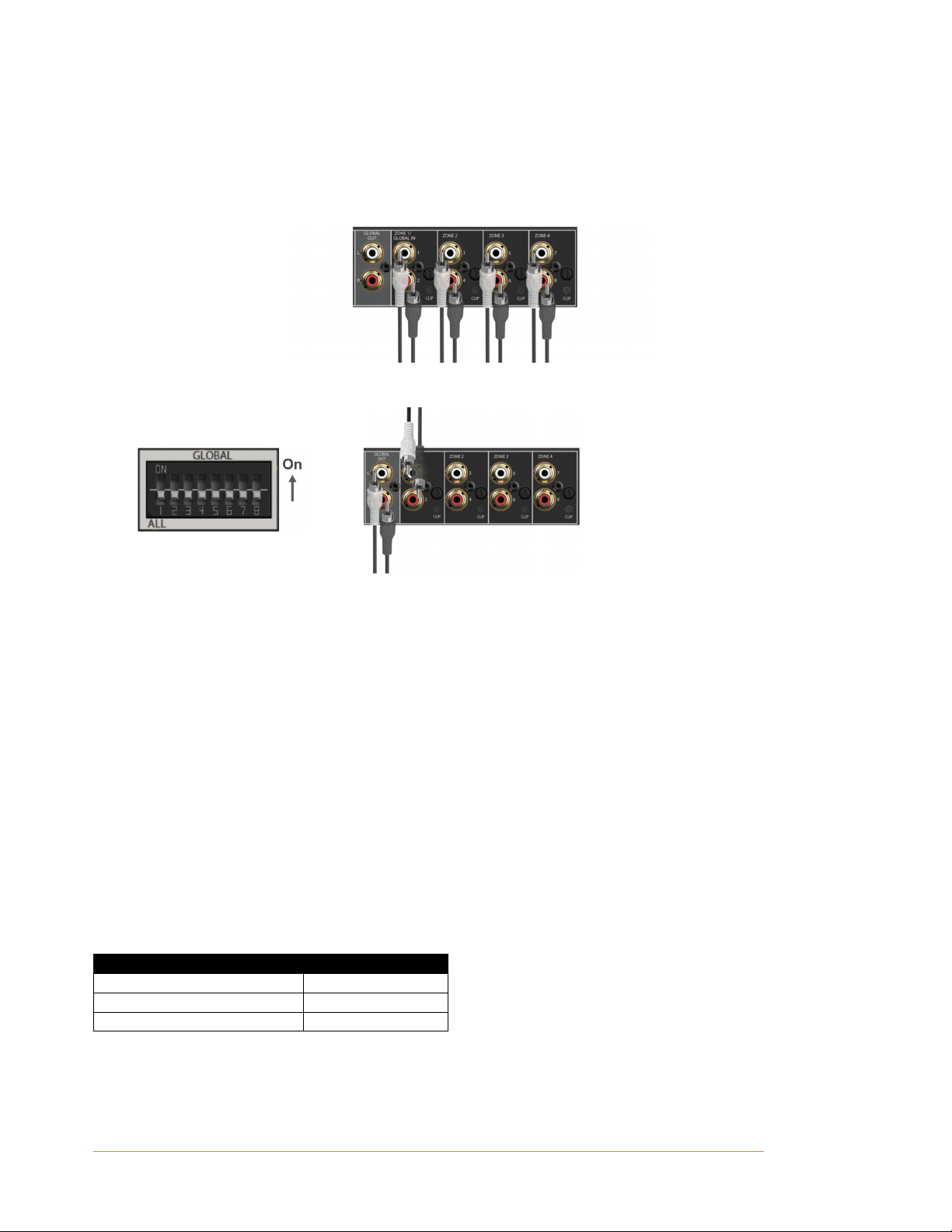
3 LINK TO GLOBAL INPUT
Set the switch to the UP position to link a
zone to the ZONE 1 INPUT/ GLOBAL
INPUT
4 POWER MODE
ON: Always On
12V: Controlled by 12VDC trigger.
AUTO: Turn on when an audio signal is
sensed on the audio input
5 12V TRIGGER IN/OUT
The Trigger In and Out connections
provide 1/8” (3.5mm) mono mini-plug
connectors.
Use the Trigger In for making
connections to external control devices
that will activate and deactivate the DA
amplifier standby mode. The Trigger Out
can be used for making Trigger In daisy-
chain connections to additional DA
series amplifiers or other components
that need to mimic the amplifier’s power
state.
6 GLOBAL OUT
Provides a line-level RCA connector
loop/pass thru output for connecting
multiple DA amplifiers in a
system utilizing a single Global input
signal.
7 ZONE 1 INPUT / GLOBAL IN
Provides a line-level RCA connector
input to feed the corresponding speaker-
level output channel.
Additionally, this input can also feed
any/all speaker output channels by
utilizing the LINK TO GLOBAL INPUT
switches.
8 OUTPUT LEVEL CONTROLS AND
CLIP INDICATOR
Provides output level attenuation per
Zone pair.
The output level controls function as
attenuators for each zone and can be
used to level-match zones in an
installation.
The CLIP indicator LED is located below
the GAIN control. If clipping is present
while playing an input source, the CLIP
LED will flash red.
9 LOCAL INPUTS / ZONE INPUTS
Provides a line-level RCA connector
input to feed a corresponding speaker-
level output channel.
When used as a multi-zone amplifier,
each channel can be provided with a
dedicated input signal. The signals from
this input will only be available on the
corresponding speaker-level output.
Local inputs are grouped and identified
both by Zone, and channel numbers 1-8
on the rear panel.
10 OUTPUT TERMINAL (PHOENIX
BLOCK) CONNECTORS
Two four-pole, touch-proof
terminal strip per channel pair.
Accepts up to 12 AWG wire or
terminal forks.

JBL DA850 DA1650 Owners Manual | rev1.2 Draft20231009
Pg 6 of 16
©2023 Harman International | Features, Specifications, and Appearance subject to change without notice.
Installation
RACK MOUNTING
CAUTION: Before you begin, make sure your amplifier is disconnected from the power source.
The DA series amplifiers are intended to be installed in a standard 19-inch equipment rack with the
supplied with rack mount ears in a 1U rack space (rack mount bolts and nuts are not included).
Installing a DA series amplifier in a rack:
1. Attach the rack ear brackets to the sides of the amplifier using the provided machine screw
fasteners into the threaded holes (1 ± 0.1Nm recommended torque).
2. Install into rack and connect cabling.
PROPER COOLING
When using an equipment rack, mount units directly on top of each other. Close any spaces in the rack with
blank panels. (Open spaces will reduce cooling efficiency.) Once mounted in the rack, ensure the sides of
the amplifier are well ventilated and that the fan openings are not obstructed. The rack should be a
minimum of 2 inches (5.1cm) away from the sides of the amplifier.
Air flow is side-to-side.

JBL DA850 DA1650 Owners Manual | rev1.2 Draft20231009
Pg 7 of 16
©2023 Harman International | Features, Specifications, and Appearance subject to change without notice.
SURFACE MOUNTING
You can also place a single amp on a solid, stable surface utilizing the provided feet and fasteners.
Once positioned, ensure the sides of the amplifier are well ventilated and that the fan openings are not
obstructed.
If the system is taken out of use for a long period, disconnect the amplifier from the mains power supply.

JBL DA850 DA1650 Owners Manual | rev1.2 Draft20231009
Pg 8 of 16
©2023 Harman International | Features, Specifications, and Appearance subject to change without notice.
Hardware Setup
CONNECTING AUDIO INPUTS
JBL recommends using pre-built or professionally wired unbalanced cables (single-ended plus shield). The
DA series amplifiers accept line-level audio connections at the RCA input connectors.
When the amplifier is used as a multi-zone amplifier, each channel can be provided with a dedicated input
signal. The signal from this input will be available on the corresponding speaker-level output.
Alternatively, each zone can be linked individually to the GLOBAL IN/ZONE INPUT 1.
Local inputs are grouped and identified in pairs, with a shared output level control.
Note that for BRIDGE/MONO operation, a stereo input will be appropriately summed to mono and outputs
can be used in either Bridge outputs or single channel pairs.
WIRING OUTPUT CONNNECTORS
Before making any output connections, ensure the power cord is disconnected from the amplifier and
carefully review the total impedance for loudspeakers connected to each amplifier output. If multiple
loudspeakers are connected to an output (i.e., in series, parallel, or series-parallel), be certain the total
system impedance is within the allowed specification for the output. See "Specifications" on page 13 and 14
for supported load specifications.
JBL recommends using two-conductor or four-conductor, heavy gauge speaker wire up to 12 AWG.
For low-impedance loads, refer to the table below and select the appropriate size of wire based on the
distance from amplifier to speaker.
Distance Wire Size
Up to 25 ft. (7.6m) 16 AWG
26-40 ft. (7.9-12.2m) 14 AWG
>41 ft. (12.5m) 12 AWG

JBL DA850 DA1650 Owners Manual | rev1.2 Draft20231009
Pg 9 of 16
©2023 Harman International | Features, Specifications, and Appearance subject to change without notice.
Speaker outputs provide connection for:
Up to four pair of stereo speakers (eight speakers total) to the DA850
Up to eight pair of stereo speakers (sixteen speakers total) to the DA1650
Connection to speakers is provided via phoenix-type connectors that accept bare wire terminations. The
connectors are grouped in pairs with one connector each for pair. Each pair consists of four wire
terminations: positive (+) and negative (–) for the Left channel and positive (+) and negative (–) for the
Right channel. To attach speaker cables to the phoenix connector, strip approximately ¼” of insulation off of
the end of the positive and negative leads of the cable and insert the bare ends into the corresponding
position of the phoenix connector, tightening the screw terminals on top to secure the termination. Repeat
this procedure for each speaker.
Do not connect the L – and R – (negative) terminals together. Doing so will result in a fault
condition and the amplifier will either shut down or not work properly.
Check the polarity of the speakers and wires prior to connecting to the amplifier.
CONNECTING BRIDGED OUTPUTS
1. Set BRIDGE/MONO as needed for each zone by moving the switch to the UP position for that zone.
2. Connect the + terminal from the speaker to the + terminal of the left channel on the amplifier.
3. Connect the – terminal from the speaker to the – terminal of the right channel on the amplifier.
The two terminals for a bridged pair of speakers are marked by + BRIDGED –
In Bridge mode, the pair of amplifier channels in a zone combine to make a mono output of double the
power. When in bridge mode the left and right channel RCA inputs to the zone are active so you can
connect one mono source (Left) or a stereo source (Left and Right) which will sum-to-mono
appropriately.

JBL DA850 DA1650 Owners Manual | rev1.2 Draft20231009 Pg 10 of 16
©2023 Harman International | Features, Specifications, and Appearance subject to change without notice.
CONNECTING THE AC POWER CORD
Connect your amplifier to the AC mains power outlet using the supplied AC power cord. First, connect the
IEC end of the cord to the IEC connector on the amplifier. Then plug the other end of the cord to the AC
mains.
The third (ground) prong of the supplied AC power cord connector is a required safety
feature. Do not attempt to disable this ground connection by using an adapter or other
methods.
Make certain the AC mains voltage and current ratings are sufficient to deliver full power to all amplifiers.
DA Series amplifiers use a universal power supply. The AC voltage requirements are 100V-240V~,
50/60Hz (±10%). If the AC line voltage varies outside of this acceptable range, the amplifier’s power supply
will turn off and the standby LED will flash RED. The amplifier will turn back on when the AC line voltage
returns to safe operating levels.
POWER UP PROCEDURE
When turning on the amplifier for the first time:
1. Connect the power cord and turn on the amplifier power using the rear AC mains rocker switch.
2. Press the front standby button to power the unit out of standby.
3. Turn your audio source up to an optimum level. If any of the amplifier’s Clip indicators light RED,
reduce the source level until the Clip LEDs no longer light.
IMPORTANT: Always turn off the amplifier — by using the rear AC mains rocker switch — and disconnect
the power cord before making any wiring or installation changes.
PRECAUTIONS
Your amplifier is protected from internal and external faults, but you should still take the following
precautions for optimum performance and safety:
1. Configure the amplifier for proper operation, including input and output wiring hookup. Improper wiring
can result in serious operating difficulties.
2. Use care when making connections, selecting signal sources, and controlling the output level.
3. Do not short the ground lead of an output cable to the input signal ground. This may form a ground loop
and cause oscillations.
Never connect the output to a power supply, battery, or power main Electrical shock may
result.
4. Tampering with the circuitry or making unauthorized circuit changes may be hazardous and invalidate
all agency listings.
5. Do not operate the amplifier with the Clip LEDs constantly flashing.
6. Do not overdrive the preamplifier/source, which will cause clipped signal to be sent to the amplifier.
Such signals will be reproduced with extreme accuracy, and loudspeaker damage may result.
7. Do not operate the amplifier with less than the rated load impedance. Due to the amplifier’s output
protection, such a configuration may result in premature clipping and speaker damage.
REMEMBER: JBL/ HARMAN is not liable for damage that results from overdriving other system
components.

JBL DA850 DA1650 Owners Manual | rev1.2 Draft20231009 Pg 11 of 16
©2023 Harman International | Features, Specifications, and Appearance subject to change without notice.
Setting POWER MODE
The three-position POWER MODE switch has three settings:
ON:
Front panel standby button activates and deactivates standby mode when the DA amplifier is
connected to AC power. When the amplifier is connected to AC power, the standby button LED
will glow dim BLUE indicating that the unit is in the standby mode. In this state, the power
amplifier section is not activated, and the unit consumes minimal AC power. Pressing the
standby button from this state will activate the power amplifier section for all zones and the
standby button LED will light up WHITE indicating that the DA is powered on.
12V:
Enables control for remote 4.5V-12VDC trigger signals used to activate and deactivate the
standby mode of the amplifier.
The Trigger In and Out connections can be used to activate and deactivate the standby mode
from devices such as remote control systems, preamplifiers or other external devices. The
Trigger In and Out connections offer 1/8” (3.5mm) mono mini-plug connectors. Use the Trigger
In for making connections to external control devices that will activate and deactivate the DA
amplifier standby mode. The Trigger Out does not provide DC power on its own but can be
used for making Trigger In daisy-chain connections to additional DA series amplifiers or other
components that need to mimic the amplifier’s power state.
NOTE: When a remote trigger is connected it will override the front panel standby
button operation.
To install a trigger cable:
Power the controlling source and DA amplifier off.
Connect the trigger cable to the controlling source and the DA amplifier.
After the connections are made, power on the controlling source and the DA amplifier.
After the source unit is fully powered up, the LED power indicator on the front of the
amplifier should be lit WHITE.
Verify the trigger is working by putting the source unit into standby mode. The DA
amplifier after a short delay will also go into the standby mode and the power indicator
will light up dim BLUE.
Once you have verified that the trigger cable is working, only use the source unit to
power on and off your DA series amplifier.
AUTO:
Enables the audio Signal Sense circuitry for the Global and Local inputs. The Signal Sense
circuitry allows the amplifier to activate a zone when an audio signal is detected at the
corresponding input and deactivate a zone when no audio signal has been present for 30
minutes.
When the amplifier is powered on and the Power Mode switch is set to the Auto position,
amplifier channels with signal present will be active. Channels without signals present will
remain switched off until signals are detected. In this mode, power consumption is lowered by
switching off idle channels and audio performance is improved by eliminating crosstalk on
adjacent unused channels. In cases where Auto is enabled and no audio signals are present
on any channels for more than 30 minutes, all channels will be switched off and only the front
panel standby button will slowly flash dim BLUE while the amplifier continues to monitor all
inputs for a signal.
NOTE: When a remote trigger is connected it will override the front panel standby
button operation.

JBL DA850 DA1650 Owners Manual | rev1.2 Draft20231009
Pg 12 of 16
©2023 Harman International | Features, Specifications, and Appearance subject to change without notice.
Output Level controls
ADJUSTING OUTPUT LEVELS AND CLIP INDICATION
Output levels are controlled per channel pair using the attenuation knobs located next to the Zone inputs on
the rear panel. The output level controls function as attenuators for each zone and can be used to level-
match zones in an installation. When turned fully clockwise, the output level is at maximum. The CLIP
indicator LED is located below the Level control. If clipping is present while playing an input source, the
CLIP LED will flash red. To operate the output level control, use a small, flat-tipped screwdriver to rotate the
controls knob so that the desired level is achieved and without clipping.
LED Status
POWER LED
LED Status
Dark/Unlit Off
White On
Dim Blue Standby
Dim Blue (slowly breathing) Standby in Auto Power Mode
Red PSU Fault
ZONE STATUS LED
LED Status
Dark/Unlit Off/Signal not present
White On/signal preset
Yellow Clipping
Red Zone Fault

JBL DA850 DA1650 Owners Manual | rev1.2 Draft20231009 Pg 13 of 16
©2023 Harman International | Features, Specifications, and Appearance subject to change without notice.
Specifications
DA850
Connectivit
y
and Control
Analo
g
audio input 8 x RCA
(
Sin
g
le Ended
)
Stereo analog global output
(g
lobal input looped to
g
lobal output
)
2 x RCA (Single Ended)
Speaker output Phoenix block connectors, accommodates up to 12AWG wire
12V trigger control 1 x 3.5mm (in)
1 x 3.5mm
(
out
)
Power Standard IEC
Global input select 4 x 2-position dip switches
Brid
g
e/Mono select 4 x 2-position dip switches
Power Mode select 1 x 3-position switch
–
alwa
y
s on, 12V, auto sense
Power
(
1kHz, 20ms burst, 2 channels driven, 0.5% THD max
)
Rated Power
(
8Ω
)
50W
Rated Power
(
4Ω
)
110W
Rated Power (8ΩBridged, one zone
driven
)
185W
Performance
Frequenc
y
Response 20Hz-20kHz +/-0.5dB, at 1/8th power, all loads
THD+N
(
max
)
, at rated power, 20-20kHz <0.1%
Signal to noise ratio (min), A-weight, 20-
20kHz, 8Ωmode >100dB
Crosstalk between any zones, at 1/8th
powe
r
-80dB
Minimum output impedance 2.7Ω
Analo
g
input impedance 20kΩ
Si
g
nal sense, wake up level 1.75 mVrms
Max. undistorted analo
g
input si
g
nal 4.6 Vrms
Fan noise, maximum, 1/8 power 50dBA SPL
@
1 meter
Electrical
Power suppl
y
Universal Mains 100
–
240VAC 50-60Hz
Standb
y
power consumption Less than 0.5W
Ph
y
sical
Max. ambient temperature 113°F
(
45°C
)
Max. operation altitude 9843ft
(
3000m
)
Dimensions
(
H x W x D
)
: 1.7” x 17.2” x 12.7”
(
43.7mm x 436.0mm x 323.0mm
)
Dimensions inc. feet
(
H x W x D
)
: 1.75” x 17.2” x 12.7”
(
44.5mm x 436.0mm x 323.0mm
)
Net Wei
g
ht: 4.5k
g

JBL DA850 DA1650 Owners Manual | rev1.2 Draft20231009 Pg 14 of 16
©2023 Harman International | Features, Specifications, and Appearance subject to change without notice.
DA1650
Connectivit
y
and Control
Analo
g
audio input 16 x RCA
(
Sin
g
le Ended
)
Stereo analog global output
(g
lobal input looped to
g
lobal output
)
2 x RCA (Single Ended)
Speaker output Phoenix block connectors, accommodates up to 12AWG wire
12V trigger control 1 x 3.5mm (in)
1 x 3.5mm
(
out
)
Power Standard IEC
Global input select 8 x 2-position dip switches
Brid
g
e/Mono select 8 x 2-position dip switches
Power Mode select 1 x 3-position switch
–
alwa
y
s on, 12V, auto sense
Power
(
1kHz, 20ms burst, 2 channels driven, 0.5% THD max
)
Rated Power
(
8Ω
)
50W
Rated Power
(
4Ω
)
110W
Rated Power (8ΩBridged, one zone
driven
)
185W
Performance
Frequenc
y
Response 20Hz-20kHz +/-0.5dB, at 1/8th power, all loads
THD+N
(
max
)
, at rated power, 20-20kHz <0.1%
Signal to noise ratio (min), A-weight, 20-
20kHz, analo
g
input, 8 Ωmode >100dB
Crosstalk between any zones, at 1/8th
powe
r
-80dB
Minimum output impedance 2.7Ω
Analo
g
input impedance 20kΩ
Si
g
nal sense, wake up level 1.75 mVrms
Max undistorted analo
g
input si
g
nal 4.6 Vrms
Fan noise, maximum, 1/8 power 50dBA SPL
@
1 meter
Electrical
Power suppl
y
Universal Mains 100
–
240VAC 50-60Hz
Standb
y
power consumption Less than 0.5W
Ph
y
sical
Max. ambient temperature 113°F
(
45°C
)
Max. operation altitude 9843ft
(
3000m
)
Dimensions
(
H x W x D
)
: 1.7” x 17.2” x 12.7”
(
43.7mm x 436.0mm x 323.0mm
)
Dimensions inc. feet
(
H x W x D
)
: 1.75” x 17.2” x 12.7”
(
44.5mm x 436.0mm x 323.0mm
)
Net Wei
g
ht: 4.5k
g

JBL DA850 DA1650 Owners Manual | rev1.2 Draft20231009 Pg 15 of 16
©2023 Harman International | Features, Specifications, and Appearance subject to change without notice.
Troubleshooting and Maintenance
Troubleshooting
The amplifier does not power on.
1. Attempt to power on the amplifier with the front panel Standby/On button.
2. Examine the power cord to ensure a good connection between the rear panel AC input connector and the wall
outlet.
3. Check the wall outlet.
The Trigger Input is connected to an external device, but the amplifier does not power on and
off with the external device.
1. Verify the trigger cable is connected at both ends and verify that the trigger cable is connected to the right
device. Also re-verify the trigger installation as instructed in the Hardware Setup section of this user guide.
2. Verify the trigger level of the output source device. The DA accepts a range of 4.5-15VDC.
Source signals are present and the system is at a suitable volume level but one or more channels
are not passin
g
audio.
1. Reduce system volume level.
2. Power the DA into standby mode.
3. Check input connections.
4. Check speaker connections.
5. Allow the amplifier to cool before powering it on again.
Audio sounds “thin” and is lacking proper bass response.
Check to ensure proper polarity of the speaker cables and connections.
Audio Levels differ between zones.
1. Check the level settings of the DA Output Level Controls.
2. Check the settings on your preamp, processor or controller.
Audio plays and then cuts off.
Check input and speaker connections for short circuits or loose connections at the amplifier and speaker.
A humming sound is present in the audio.
Audible hum, or a discernable low frequency noise is one of the most common problems within audio/video
systems. This problem, even when the volume is at a low level, is usually caused by a common problem known as
a “ground loop”. A ground loop occurs when there is a difference in ground voltages between two or more
components that are connected electrically. In most cases, one or more of the following suggestions below will
solve the hum problem.
1. Disconnect components one at a time to isolate the problem. Once the problem is identified, make sure the
associated component is properly grounded and connected to the same electrical ground as the DA amplifier.
2. Turn off all components within your system and then disconnect the input cables on the DA amplifier. Turn the
amplifier back on. If the hum disappears the fault may be with the input cables that are being used. Make sure
the cables are properly shielded or use a cable that has better shielding. Make sure the cable is not running or
laying on top of any AC power cords.
3. Ground loop problems may also be caused by poor grounding of the electrical system within your home or may
be caused by faulty earth grounds in your home’s electrical system. To isolate the problem, try unplugging
components with three prong grounded power cords one at a time to see if one or all are causing the problem.
Please check with a licensed electrician for further evaluation.
If all else fails…
1. Contact an authorized JBL dealer.
2. Contact JBL Customer Technical Support
Maintenance
Routine maintenance should be performed on a periodic basis. Clean the exterior surfaces of the unit with a soft, dry,
lint-free cloth. Do not use alcohol, benzene, acetone-based cleaners, or strong commercial cleaners. Do not use a
cloth made with steel wool or metal polish. If the unit is exposed to a dusty environment, a low-pressure blower may
be used to remove dust from its exterior.

Harman International Industries, Incorporated.
8500 Balboa Blvd, Northridge CA 91329 United States.
European Representative: Harman International Industries, Incorporated.
EMEA Liaison Office, Danzigerkade 16G, 1013 AP Amsterdam, The Netherlands.
UK Business Address: Ground Floor, Westside 2, London Road, Apsley, Hemel Hempstead,
Hertfordshire, HP3 9TD, United Kingdom.
© 2023 Harman International Industries, Incorporated. All Rights Reserved.
JBL is a trademark of Harman International Industries, Incorporated
registered
in the United
States and other countries.
Features, Specifications, and Appearance subject to change without notice.
JBL DA850 DA1650 Quick Start Guide | Rev 1.2 Draft20231009 | Features, Specifications, and Appearance subject to change without notice. Pg 16 of 16
This manual suits for next models
1
Table of contents
Other JBL Amplifier manuals

JBL
JBL GT-X646 User manual

JBL
JBL 1214 User manual

JBL
JBL GTS100 User manual

JBL
JBL SYNTHESIS S5160/230 User manual

JBL
JBL Grand Touring Series GTO14001 User manual

JBL
JBL P80.4 User manual

JBL
JBL 6230 User manual

JBL
JBL STADIUM 4 User manual

JBL
JBL Synthesis SDA-1700 User manual

JBL
JBL GTR-7535/104/102 User manual