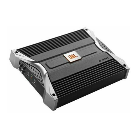
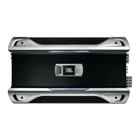
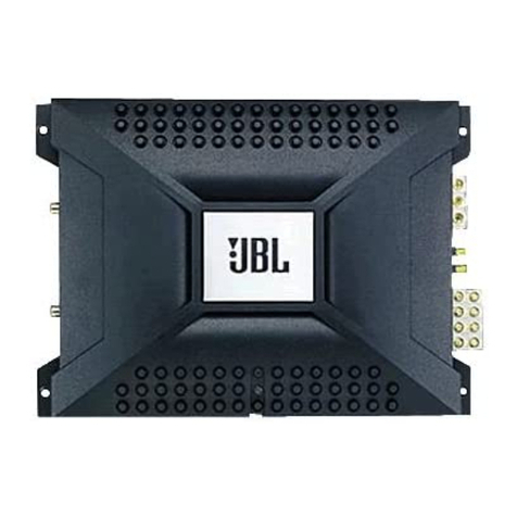
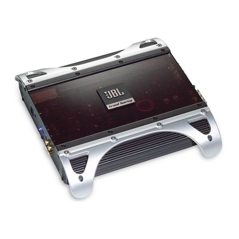
JBL Grand touring series User manual


Introduction ...................................... 3
Features .................................... 4
About Installation ............................. 4
Quick Start ...................................... 5
System Design Using the GTSlSOx ..................... 6
Speaker Requirements .......................... 6
Signal Sources ................................ 7
Other Components ............................. 7
Typical Applications ........................... 8
Warnings and Tips ................................
10
Installation Precautions. ........................ 10
Mounting Locations ............................ 11
Installation and Use ............................... 12
Controls and Connectors ........................ 12
Internal Adjustments ........................... 14
Speaker-Level Input Impedance Adiustments ..... 14
Crossover Frectuencv Adiustments ............. 14
Mounting Positions ............................ 16
Wiring.. .................................... 17
Power Connections ......................... 17
Ground Wire .............................. 18
Remote In/Out Connection .................... 18
Mute Connection ........................... 19
Speaker Connections ........................ 19
Audio Input Connections ..................... 22
Line-Level Input Connections .............. 22
Speaker-Level Input Connections ........... 22
Simultaneous Speaker Level and Line Level ... 23
Using Rem-Out Capabilitv
Input Mode Switch . . . . .
Input Gain Adiustment . . . . . . .
Adiusting the Gain . . . . . . .
Other Important Characteristics . . .
Maintenance . . . . . . . . . . . . . . .
Add-On and Upgrade Steps . . .
In Case of Difficulty . . . . . . . .
Solving Noise Problems . . . .
Svstem Noise . . . . . . . . . .
Vehicle Noise . . . . . . . . . . .
Specifications . . . . . . . .
Warranty . . . . . . . . . . .
Serial Number
Dealer Name
......
......
......
......
......
......
......
......
......
......
......
......
......
......
......
......
......
......
......
......
.
23
. . 24
. . 25
25
. . 26
. . 27
. 27
. . 31
. . . 32
. 32
. 32
. . 36
. 38
City, State, Zip
Sales Receipt Number
Date of Purchase

Introduction
Thanks for purchasing your new
GT series automotive amplifier.
The GT series amplifier you have
chosen includes many unique
features to enhance its perfor-
mance and utility. The power
amplifier circuitry is a fully
discrete design notable for its
low distortion and unusually
clean and clear sound qualitv.
Your GT series amplifier will
easily connect to virtually any
car audio svstem, whether it is
factory installed or purchased
separately.
In addition to conventional pre-
amp-level inputs, this model fea-
tures JBL’s Universal Interface
design, which facilitates simple
connection to factory radios with
the low distortion that is usually
only associated with preamp-
level connection. With Universal
Interface, a factory radio can be
used either as the main music
source or combined with a CD
player or changer which includes
volume control capability,
simultaneouslv connected to the
amplifier. BY providing this two-
unit direct connection, Universal
Interface circuitrv eliminates the
need for an FM modulator to
interface a CD player to factory
radios, improving the fidelity of
digital plavback.
In addition, when using a hish-
powered (BTL) radio through
the speaker-level inputs,
Common Sense turn-on circuitrv
senses the common-mode voltage
present on the radio’s speaker
wires, turning the amplifier on
without an additional “remote”
wire.
Also, the built-in active
crossover provides either full-
range, high-pass or low-pass
operation. This lets your GT
series amplifier power either
subwoofer or component speak-
ers in a biamplified system, or
conventional full-range
speakers
in simpler systems.
The GTS180x includes preamp-
level
outputs
which can provide
either full-range, high-pass or
low-pass signal to drive addi-
tional amplifiers. This lets YOU
build systems of virtually any
design without requiring a sepa-
rate electronic crossover.

Features
l
Bridgeable Z- or l-Channel
Operation
l
Simultaneous Stereo + Mono
Operation
l
Built-in lEdB/Octave Freauencv-
Selectable High-Pass and
Low-Pass Crossover
. Preamp Output with Frequency
Selectable High-Pass and
Low-Pass Crossover
l
No Current Limiting
l
Oversized Floating Rail (OFR)
MOSFET Switch-Mode Power
SUPPIV
l
Common Sense 2-Wav Turn-On
. Switchable Bass Boost
. Mute Input - accepts standard
noise gate inputs to silence the
amp during no-music conditions
l
Stealth Remote Silent Turn-On
Circuitrv with Power-On
Indicator
l
Continuouslv Adiustable Gain
Controls
l
Capable of Single-Ended
Operation Into 2-Ohm Loads
l
Full Complementarv, Direct-
Coupled, Discrete Power
Amplifier Circuitrv
l
Gold-Plated RCA Input
Connectors
l
Gold-Plated Power and Speaker
Connectors
l
Third Order (18dB per Octave)
Capacitive/Inductive
Power-Supplv Filtering
l
Input Mode Switching
l
Speaker Output
Short-Circuit Protection
About Installation
Although the GTSlEOx is designed
to make installation as easv as
possible, this is a sophisticated
product that requires proper
installation to realize full perform-
ance potential. Skill with tools, an
understanding of basic electron-
ics,
and experience
with car
stereo installation is needed to
properlv install this amplifier.
If YOUfeel YOUdo not have the
necessary knowledge and skills
we stronslv recommend that the
installation be performed bv Your
authorized JBL dealer. If the
GTS180x amplifier is installed bv
an authorized JBL dealer, we will
double the length of vour war-
rantv to two years from date of
purchase. Please retain a COPYof
your bill of sale to ensure this
additional coverage.
If you choose to install the GTS
amplifier vourself, read all of the
information in this manual before
you start the installation. Pav
particular attention to the safetv
precautions and notes.
It will save potential problems
later if you take a few minutes to
plan the complete installation
before you start. The routing of
wires, the power SUPPIV
connec-
tion points, and the mechanical
installation of the unit should be
completelv thought out before
you begin. Work carefullv and
check each step as it is per-
formed. Before operating the
amplifier, recheck the entire
installation to be sure that each
connection is correct, properly
insulated and secure.

Quick Start
Recommended for
experienced professional
installers only!
Refer to the “Crossover Frequency
Adiustments” and “Speaker-Level
Input Impedance Adiustments”
sections of this manual to see if
YOUwill need to make alterations
to their factory settings. If you are
not using the built-in crossover, or
the speaker-level inputs, you may
skip this step.
1. Disconnect the negative
cable from the battery.
Note: If the vehicle’s radio
features a code-type security
system, make certain YOU
know the code before
disconnecting the battery!
2. Run the recommended mini-
mum (or larger) power cable
(see the swcifications) com-
plete with a fuse (not included)
directly from the oositive
+12V battery terminal to the
desired amplifier location.
Use a 30 amp fuse. Keep the
fuse to within 6” of the battery
terminal, and before the wire
runs through any metal
partition.
Note: All wiring connections
should be made either by solder-
ing with heatshrink tubing insula-
tion or with high-quality crimp-
type insulated connectors installed
with a professional, articulated
crimping tool. Soldering crimp-
type terminals is recommended
for additional security. Never use
wire-nuts, insulation-displacement
connectors (i.e. ScotchLok type),
or “twist and tape” connections.
Do not use elec trical tape; it will
loosen with age and extreme
temperatures.
3. Mount amplifier in the desired
location using four screws.
4. Connect power wiring as
shown in the wiring diagram
on page 17.
5. Connect the outputs from the
head unit to the appropriate
inputs of the amplifier
according to the wiring dia-
gram (page 17) with either
high quality low-level signal
cables (twisted pair is.best)
with RCA plugs, with the
supplied speaker-level input
connector, or both.
6. Connect the speakers to
the amplifier according to
the wiring diagrams on
Pages 8 and 9.
7. Turn the input gain adiust-
ment to the l/4 position.
8. Set the crossover switches as
desired.
05
9. Set the input mode switch to
stereo, left + right or risht-
input-only operation.
10. Set the bass boost switch to
the desired position.
11. Reconnect the negative bat-
tery cable.
12. Turn on the signal source at a
low volume level and check
for the correct output from
each speaker.
13. Adiust the amplifier gain con-
trol using the Procedure
described in the “Adiustins
the Gain” section (page 25).
14. Read the rest of the manual to
get maximum use ond enioy-
ment from your amplifier.

System Design Using the GTSl80x
Speaker Requirements
When used in the non-bridged
mode the GTS180x can easily
drive 2-ohm speaker loads. When
only one speaker is connected to
each channel, virtuallv anv
conventional speaker can be
used. When two speakers are
connected in parallel to a given
channel, each speaker must have
a minimum impedance of at
least 4 ohms. This ensures that
the combined load will not drop
below 2 ohms. Although the
amplifier will not be damaged,
load impedances lower than
2 ohms will eventually cause the
amplifier to overheat, activating
the Protection circuits and
causing the unit to shut off until
it cools down sufficientlv.
Parallel Wiring
(+I
8 Ohms
Nomtnal
Impedance
When the GTS180x is in bridged The GTSlEOx must not be used
mode, the combined impedance with speakers that have either
of the speaker (or speakers) con- one of their input terminals wired
netted to the bridged channel to the frame of the speaker or to
should be at least 4 ohms. the chassis of the vehicle.
Sustained operation of the
GTSl8Ox in bridged mode with
less than 4 ohms will likely cause
overheating. If monaural ooera-
tion is desired, and two 4 ohm
speakers are used, it is best to
connect each speaker to an indi-
vidual amplifier channel and use
the “L+R” mode on the input-
mode switch to provide monaural
operation.

Signal Sources
The low-level preamp outputs of
any radio/tape deck, CD player
or nreamol equalizer so equipped
can drive the GTS180x. The gain
control of the GTSlBOx is used to
match the amplifier’s input sensi-
tivity to the outout voltage of the
source. This matching is impor-
tant to keep the noise level low
and is explained in the “Adiusting
the Gain“ section of this manual
(see page 25).
Thanks to Universal Interface
circuitry, the GTS180x can also
be connected to power amplifiers,
radios or equalizers that are
equipped with only speaker
outputs bv connecting them
through the speaker level input
connector. Inside the GTSlEOx,
the speaker-level and preamp-
level inputs are connected
through a mixing circuit, which
allows them to be used
simultaneously. Therefore a low-
level source, such as a CD player
equipped with a volume control,
may be connected to the preamp-
level inputs at the same time as a
powered radio/tape unit is
connected to the sneaker-level
inputs. This provides a higher
performance alternative to an
FM modulator connection when
YOUwish to add CD capability to
a factory cassette stereo.
Switching from one source to the
other is as simple as turning the
desired source on and turning the
undesired one off - no additional
switches or relay connections are
needed.
Other Components
The system options of the
GTSlEOx are numerous. All JBL
amplifiers are designed with
sufficient adiustment range to
match with the accepted “nor-
mal” voltages and impedances
used by virtually all car audio
components. With very few
exceptions, the GTSlEOx will
match up with nearly anv
equipment you already have.

T’ypicclI ~~~~~~~t~~~s
The following diagrams show the
most common basic svstem
configurations of the GTS180x.
One or more of these “building
blocks” may be combined to
form elaborate system designs.
For additional ideas, refer to the
“Add-On and Upgrade Steps”
section (see page 27).
Application 1
Stereo Full-Range or Subwoofer Operation
Application 2
Bridge-Mode Operation
Sing/eAmplifier:
Subwoofer Operation (Mono)
DualAmplifier:
Subwoofer Operation (Stereo)

Application 3
Bi-amplified, Three-Channel
SubwooferEatellite Svstem.
Application 4
Bi-amplified System Using
Preamp Output Capability.

Warnings and Tips
Fnstallation Precaufims
10
Before beginning the installation
of the amplifier read the follow-
ing points carefully. Failure to
heed these warnings could result
in personal iniury or damage to
property.
l
The GTS180x should be installed
only in vehicles that have 12-
volt negative ground electrical
systems. Connection to other
types of electrical systems may
damage the amplifier and/or the
vehicle’s electrical system.
l
Before beginning the instollo-
tion, disconnect the negative
(ground) cable from the vehi-
cle’s battery. This will prevent
accidental short circuits while
working on the installation.
Reconnect the cable only after
the installation is complete and
the wiring has been carefully
checked to be sure there are no
exposed wires or short circuits
and everything is properly and
securely connected. Note: If the
vehicle’s radio features a code-
type security system, make cer-
tain YOUknow the code before
disconnecting the battery!
l
Work in an area that is well
ventilated.
l
Wear eve protection whenever
cutting, drilling or filing any
parts of the vehicle.
l
Wear ear protection when using
high-speed drills, saws, sanders,
or grinders. We want YOUto be
able to eniov the system once it
is installed.
l
Before cutting or drilling any
holes in the vehicle, inspect the
area carefully to be sure there
are no electrical wires,
hydraulic brake lines, fuel lines,
or fuel tanks that may be dam-
aged while doing so. Such com-
ponents may be hidden within
double-walled panels or struc-
tural members of the vehicle, so
be extremely cautious.
l
Do not bypass or modify the
fuse on the chassis of the ampli-
fier. Do not replace the fuse
with one rated for higher cur-
rent levels. Doing so could
result in damage to the ampli-
fier and the vehicle’s electrical
system. Repeated blowing of the
power supply fuse indicates a
problem within the amplifiers or
improper installation.
l
An additional power SUPPIY fuse
(not included) must be located
as close as possible to the bat-
tery on the +12V wire to mini-
mize the chance of electrical
system damage or fire in the
event of a short circuit in the
power SUPPIY wire. This precau-
tion is extremely important; do
not ignore it! If the heavy-gauge
power wire required with the
GTS180x ever becomes shorted
to ground, the wire will get
extremely hot, causing the insu-
lation to burn off, and this will
likely cause a fire if the
circuit is not properly fused.

Mountins Locations
There are several factors to con-
sider when selecting a mounting
location for the GTSlEOx.
l
It must be solidly mounted in a
place where it will not be sub-
iected to excessive shock and
vibration.
l
Under no circumstances should
the amplifier be mounted where
it will be exposed to moisture or
extreme heat.
l
Trv to mount the amplifier
where the main +12V power
supply
terminal, which must be
connected directly to the
battery, can be kept relatively
short.
l
The GTSlEOx must be mounted
in a place where air can circu-
late around the fins on the chas-
sis. Good air circulation around
the amplifier will make it oper-
ate at lower temperatures and
reduce the chance of triggering
the thermal protection circuits.
The installation positions that
provide the most efficient air
circulation around the amplifier
are shown at right.
l
Use a mounting location that -
allows access to the wiring con-
11
nections and level adiustments.
This allows the unit to be
mounted before these connec-
tions and adiustments are
made. If the amplifier must be
mounted in an inaccessible loca-
tion, it may be easier to mount
it after the wiring connections
and level adlustments are
complete.

Installation and Use
Controls and Connectors
1. Preamp-Level Input Connector
- Use these connectors for line-
level (preamp-level) input to the
amplifier.
2. Preamp-Level Output
Connector- Use these outputs
to send a line-level signal to
additional amplifiers.
3. Speaker-Level Input Connector
- Use this connector for speaker-
level input signals. A wire har-
ness is supplied for use with this
connector. See “Speaker-Level
Input Connections” section (page
22) for wiring instructions.
This input also includes JBL’s
Common Sense input circuitry,
which turns the amplifier on as
soon as the high-powered head
unit connected to this input is
turned on.
B
Mute
hlQUt
0 BatteryGround
1
8 Battery(tlzv) In &&or
0 SpeakerOutputS
0 High-LevelSQeakel
Q PreamQ-LevelRCA
0 Preamp-LevelRCA
0 GainControl
0 PreampCrossover
FrequencySelector
@AmplifierCrossover
FrequencySelector
@IInputModeSelector
8 BassBoost

4. SPeaker Output Connector -
Connect speaker wiring to this
connector. See “Wiring” direc-
tions for more information.
S., 6., 7., 8. Power Connector -
Connection for power, remote,
and muting wires. See “Power
Connections” for information on
Prover connections (page 17).
9. Fuse-30-amp ATC type.
10. Gain Control - Use this con-
trol to odiust the input sensitivitv
of the amplifier. See the
“Adiusting the Gain” section for
tips on proper setup.
11. Preamp-Output Crossover
Switch - This switch controls the
built-in crossover that is directed
to the preamp-output connectors.
Set the switch to “Flat” for full-
band operation. Set this switch to
“Low-Pass” to activate the low-
pass filter on the preamp output
(for subwoofer use). Set the
switch to “High-Pass” to activate
the high-pass filter for use with
satellite speakers on the preamp
outputs.
12. Speaker Output Crossover
Switch -This switch controls the
built-in crossover that is con-
nected to the power amplifier cir-
cuitry. Set the switch to “Flat”
for full-band operation. Set this
switch to “Low-Pass” to activate
the low-pass filter on the ampli-
fier (for subwoofer use). Set the
switch to “High-Pass” to activate
the high-pass filter for use with
satellite speakers.
13. Input Mode Selector - This
switch is used to set the input
mode for both preamp- and
speaker-level inputs.
Set this switch to Stereo for
normal operation using both left
and right inputs. Set this switch
to “R” to drive both the left and
right output channels with only a
single input on the right channel.
Set this switch to “L+R” to sum
the left and right inputs for a
mono output on both amplifier
channels. The input mode
selection switch does not effect
the preamp outputs.
14. Bass Boost Switch - This acti-
vates a built-in Bass Boost circuit
used to increase low-bass output.
Power Indicator LED (on chassis
top) - LED steadily illuminates
13
for normal operation. LED blinks
when either protection circuitry
or muting is engaged and during
initial power-up.

14
Snternal Adiustments
Speaker-Level Input
Impedance Adiustments
The speaker-level inputs of the
GTSlEOx come factory-set at lOOk-
ohms input impedance. This will
provide the lowest distortion opera-
tion from the speaker outputs of
most modern head units by reduc-
ins the power that the source unit
amplifier must deliver to practicallv
nothing. The resulting signal will
practicallv be as free from noise
and distortion as a oreamp-level
connection. On some older or lower-
priced head units, this load will not
facilitate proper fader operation. To
allow for this, we have provided the
ability to change the input imwd-
ante of the speaker-level inputs to
15ohms. This is accomplished bv
setting the jumpers as shown in the
diagram at right.
l
If the head unit has four chon-
nels of built-in amplification
and/or an electronic fader con-
trol, YOUshould leave the
jumpers in the factory set posi-
tioh (lOOk ohms).
l
If the head unit has two chan-
nels of amplification, with a
speaker-level fader, the
jumpers should be set to the 15
ohm position. This will always
be a rotarv-type control, not one
controlled by electronic push-
buttons.
If YOUare not certain of the type
of fader control your unit has,
measure the resistance across
one set of speaker outputs with
an ohmmeter (with the head unit
off). Adiust the fader control
through its entire adiustment
range. If there is a change in the
resistance as the control is
adiusted, set the iumpers to the
15ohm position.
Crossover Frequency
Adiustments
The GTSlEOx includes built-in fre-
auencv selectable crossovers. One
crossover is connected in series
with the amplifier circuitry and
the other crossover is connected to
the preamp level output iocks.
These crossovers can be set in
either the “flat” (full bandwidth
operation) configurations, Low-
Pass (subwoofer operation), or
High-Pass (satellite operation)
configurations. More details on the
use of these crossovers are given
in the “Add-On and Upgrade
Steps” section.
l
The crossover frequencies are set
by “chips” inside the amplifier
(see specification section for fac-
tory settings). These “chips” are
simplv a set of resistors, con-

netted across the pins and
molded into a single package.
The crossover frequencies mav
be changed to any value desired
by changing the resistor network.
JBL has “chips” available in the
popular values listed in the table
below. If none of these suit your
system, you may purchase com-
patible resistor networks from a
local electronics store, or you
may build your own custom val-
ues from discrete resistors
mounted on a 14-pin “DIP
Header” using the instructions
which follow.
Frequency Resistor
JBL Part
Value Number
50Hz 47k D l-23-750
80Hz 33k R 1-23-817
120Hz 22k Q l-23-820
200Hz 12k C’ 1-23-821
_... -
250Hz
375Hz
5OOHz
650Hz
10k R l-23-81 0
6.8k D l-23-822
4.7k R 1-23-815
3.9k R l-23-823
2.5kHz lk R l-23-824
5kHz 410 R 1-25816
Regardless of whether YOUbuild
or buy it, the necessary resistor
network has the followins
configuration:
Custom “Chip” Construction
l
Each resistor in the package
has the same value.
l
If you know the crossover fre-
quency you want, you can calcu-
late the resistor value neces-
sary by solving the followins
equation:
Resistor 2,500,OOO
Value = Crossover
in Ohms Frequency in Hz
*Use the following equation if YOU
have a resistor pack of a known 1 5
value, and want to find its
crossover frequency:
Crossover 2,500,OOO
Frequencv = Crossover
in Hz Resistor Value
in Ohms
l
To build “chips” from discrete
resistors, solder the resistors to
a standard 1Gpin “DIP Header”
according to the diagram. If a
DIP Header is not available, you
may bend the leads of l/4-watt
resistors 90 degrees, trim them
to l/8”-length, and insert them
directly into the chip sockets.
To change the crossover fre-
quency, change the resistor
network as follows:

1. Remove the screws from the
bottom panel as shown here.
‘2. Select which resistor module,
high pass or low pass, that
YOUwish to change.
3. A chip puller, which can be
obtained from any electronics
store, is used to remove the
resistor chip. Pull the resistor
chip from the socket as shown
in the figure at right.
4. Place the new module in the
socket making sure all pins
are lined up with the socket
holes. Press the module
firmly into the socket.
5. Replace the bottom lid.
For further information on how to
use the speaker output and pre-
amp output crossovers for system
building, see the “Typical
Applications” and “Add-On
and Upgrade Steps” sections.
Mounting Positions drilled. Put washers on the four
Place the amplifier in the instal- sheet metal screws provided and
lation location. Use a pen or pen- drive them into the mounting
cil to mark the four mounting panel. Tighten the screws evenly
screw hole locations. Set the until the unit is solidlv mounted.
amplifier aside and drill the holes
for the mounting screws. (Note:
If the surface YOUare mounting
the amp to is covered with car-
peting or upholstery, cut a small
“x” in the material at each screw
hole location before drilling the
holes. This will help prevent tear-
ins or stretching of the material
and carpet fibers from being
Pulled out.) Set the amplifier in
position and align the holes on its
side with the holes previouslv

Wiring
Proper wiring of the GTS180x
and the associated components is
extremely important for proper
performance and long- term reli-
ability. Using the proper type of
wire is very important. If a spe-
cific tvoe of wire is required for
a certain application, it will be
noted.
Route the wiring through the car
carefullv. Do not allow wires to
lay against sharp sheet metal
edges or any other surfaces that
might wear away or cut through
the insulation of the wire. Use
insulated strain reliefs, rubber
grommets and plastic tubing to
protect the wires whenever thev
are run through sheet-metal pan-
els or are placed where thev
might be pulled or damaged.
Power Connections
The power input, remote turn-on, 1 7
and mute wires are connected
to the GTS180x via the power
connector on the end of the
amplifier.
+12V Battery Wire
l
Connect a wire directlv from the
+12V terminal of the batterv to
the (+I batterv terminal on the
amplifier. Use a wire at least as
large as the recommended mini-
mum in the specifications. Use
wire that is heat- and oil-resis-
tant whenever running wires
through the engine comnart-
ment. All wire-to-wire connec-
tions should be soldered and
insulated with heatshrink tubing,
or connected through a hish-
qualitv insulated crimp-on con-
nector or secure set-screw type

18
terminal blocks. Never leave
bare wire exposed. Terminate
wires with crimp or solder-on lug
terminals whenever appropriate.
l
The GTSlI30x will draw large
amounts of current from the
vehicle’s electrical system,
enough to overload conventional
vehicle wiring. Therefore, the
+12V power supply must be taken
directly from the positive side of
the battery. Do not connect to the
vehicle’s fuse block or to a wire
feeding other accessories.
l
To prevent electrical system
damage or fire, a fuseholder and
a 30-amp fuse (not included),
must be installed in the power
supply wire, as close to the bat-
tery as possible, and before the
wire travels through the firewall
or other metal panel.
Ground Wire
l
Proper grounding is extremely
important. Use a heat- and oil-
resistant stranded copper auto-
motive wire equivalent to the size
used for the +12V connection.
Crimp or solder and insulate any
wire-to-wire connections. Keep
the ground wire as short as possi-
ble. A ground wire must be sol-
idly connected to a major sheet-
metal structure of the vehicle
such as a panel near the amp’s
mounting location. Scrape all
paint and primer off the sheet
metal at the grounding point to
ensure a good electrical connec-
tion. Attach the wire to the
grounding point with a nut, bolt
and star washer. The high cur-
rent demanded by high-powered
amplifiers requires a more
secure ground than a typical
sheet-metal screw will provide.
l
In some vehicles, such as those
that have non-metal bodies, it
may be necessary to extend the
power supply ground wire and
connect it to a frame rail or even
directly to the negative (-) termi-
nal of the battery.
l
When used in elaborate systems
with multiple components, it is
common practice to ground all
of the amplifiers and signal
processors to the some point to
prevent noise pickup from a
ground loop. With the extremely
high-peak current demands of
high-powered amplifiers, this
can result in unstable power
delivery to the components due
to modulation of the power
ground point by the high power
demands. The advanced, iso-
lated power supplies used in the
GTS amplifiers make common
ground installation unnecessary.
To prevent ground loops, they
can besrounded close to their
mounting positions. Use of
heavy-gauge wire for all
grounding, even of signal proces-
sors and head units, can mini-
mize possible noise pickup.
Remote In/Out Connection
l
The remote power control system
turns off the GTS18Ox when not in
use to prevent discharging of the
vehicle’s battery. Because the JBL
GTS18Ox includes Common Sense
l-way turn-on, when using the
speaker-level inputs with a head
unit that includes a BTL power
amp, it .is not necessary to connect
the remote wire. The amplifier will
automatically activate whenever
YOUturn on the head unit. If you
are using the line-level inputs, or

the speaker-level inputs with a
head unit that does not have a
BTL wwer amp, follow the
remote wire connections listed
below.
l
Usins the REM IN feature -
When +12V is applied to the
remote IN/OUT terminal the
amplifier is turned on. A red
LED on the top panel of the
amplifier will illuminate to indi-
cate the amplifier is on. If the
head unit has a +12V automatic
antenna or amplifier remote acti-
vation wire, connect it to the
“REM IN/OUT” connector on the
GTS180x. When the amplifier is
turned on, there is a time delay
of several seconds (longer in cold
weather) before the amplifier
will produce sound. This elimi-
nates the chance of annoying
noises produced by the radio or
signal processors being amplified
and passed to the speakers when
the system is first activated.
l
Some head units have no auto-
matic antenna or power amp acti-
vation wire. Others have automat-
ic antenna wires that are “on”
only when the radio is used but
not when a tape is played. In such
cases, connect the remote in turn-
on terminal to an unused acces-
sory terminal in the fuse block, or
any other +12V source that is
turned on and off with the vehi-
cle’s ignition switch. The remote
on/off system draws negligible
current so a relatively small (18-
or 20-gauge) wire may be used.
l
Using the REM OUT feature -
The “REM IN/OUT” terminal of
the GTS180x may be used to turn
on other amplifiers when the
GTS18Ox is being turned on by the
Common Sense Circuitry in the
sneaker-level input. Simply con-
nect the head unit soeaker-level
outputs to the GTS180x’s sneaker-
level inputs and connect the
“REM IN/OUT” terminal to the
remote in terminal of other
amplifiers or signal processors.
The GTS180x will turn on the
other amps or processors whenev-
er the Common Sense circuitry
turns on the GTSlEX3x.
Mute Connection
The GTS180x includes a mute
input terminal. This amplifier will
mute when a 5V to 12V DC signal
is applied to the “mute” input and
will be in normal operation mode
with either a ground or nothing
connected to the “mute” input.
This “mute” input is compatible
with any aftermarket noise gate
that puts out a control voltage of
+SV to +12V DC.
Speaker Connections
l
When connecting speaker wires,
be sure that no uninsulated wire
remains exposed and no loose
strands of wire touch either an
adjoining wire or terminal or a
metal surface. Securely crimp or
solder all connections and insu-
late them with heatshrink tubing.
l
Use high-quality 16 gauge or
larger (12 gauge maximum)
speaker wire for the amplifier-
to-speaker connections.
Larger wire or special hish-
performance speaker cables
may improve the performance
of some systems.
19

l
Be verv careful when speaker
20
wire is routed through a door
hinge area to door-mounted
speakers. Use grommets and
strain reliefs wherever necessary
to prevent damage to the wires.
l
The proper speaker connection
depends on whether the
GTSlSOx is used bridged or
stereo. The speakers are con-
nected to the speaker output
connector.
l
To get proper bass response and
stereo imaging, all the speakers
in the svstem must be “in
phase.” The input terminals of
the speakers will be marked in
some way to identify positive
and negative polaritv. Make
sure that the positive f+) speak-
er terminal is attached to the
positive (+) amplifier connec-
tion in every speaker-to-amp
connection. All two-conductor
speaker wire has one conductor
marked in some way so it can
be easilv traced.
l
Stereo Connection - Connect
each speaker to appropriately
labeled terminals of the speaker
output connector.
l
Bridged-Mode Connection -
Connect the loudspeaker positive
(+) terminal to the RIGHT chan-
nel positive amplifier speaker out-
put terminal. Connect the loud-
speaker negative (6) terminal to
the LEFT channel negative
amplifier speaker output termi-
nal. The input-mode switch should
be set to “RIGHT” or “L+R.”
l
Simultaneous Stereo •k Mono
Connection - The GTS amplifier
may be used to drive a stereo
pair of speakers with a mono
speaker at the same time. This
is sometimes used for center-
channel applications or for inex-
pensive subwoofer addition,
essentiallv creating a 3-channel
svstem. Unlike a true biampli-
fied subwoofer connection, how-
ever, this type of svstem config-
uration does not provide fine
control of subwoofer-satellite
balance. It requires the use of a
passive subwoofer crossover
instead of the superior active
circuitrv alreadv built-in to the
GTSlSOx, and it does not sepa-
rate the power amps driving the
satellites from the amps driving
the subwoofer. Therefore, this
connection is best used for addi-
tion of a center-channel speaker,
or as an interim step as you
build
UP
to a true biamplified
subwoofer/satellite svstem.
Connect the main pair of stereo
speakers as in the stereo mode;
connect the mono speaker as
described above for bridged-
mode connection. For use in
center-channel applications, a
high-power “L-Pad” or power
fader can be used to attenuate
the center channel for proper
level matching. For subwoofer-
satellite use, connect a non-
polarized capacitor in series
with each main speaker, and a
high-power inductor (coil) in
series with the subwoofer. Your
authorized JBL dealer will help
YOUchoose the correct values
for your particular components.
In this configuration, each
speaker should have an imped-
ance which is equal or greater
than 4 ohms. The input-mode
switch should be set to
“STEREO” (see page 24).
Other manuals for Grand touring series
5
Table of contents
Other JBL Amplifier manuals