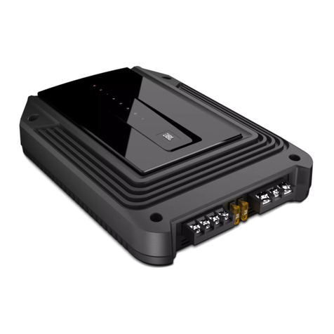
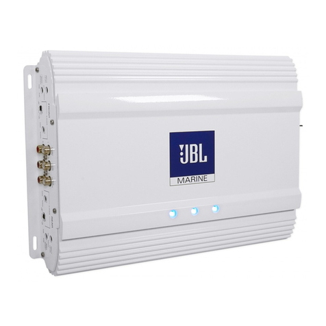
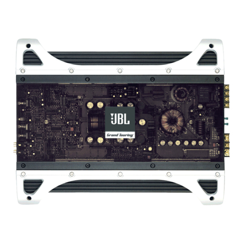
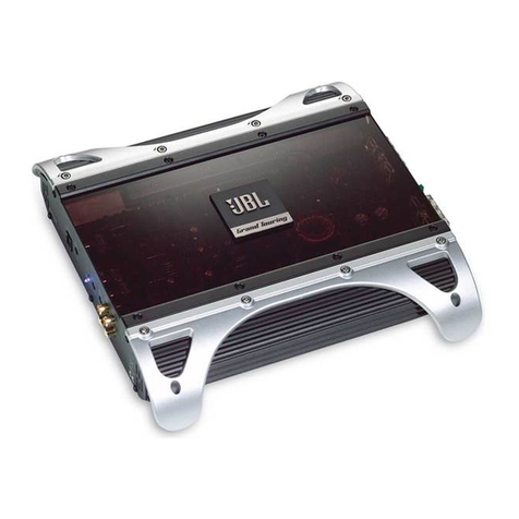
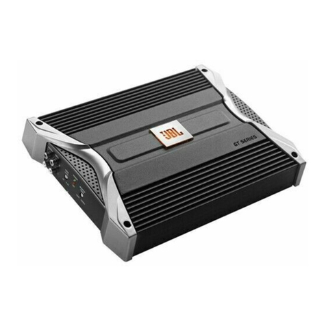
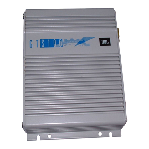
JBL GX-A604 User manual

GX-A604/GX-A602/GX-A3001
power amplifier
OWNER’S MANUAL
EnglishFrançaisEspañolDeutschItaliano
Русский
日本語영어
Nederlands
Svenska
Dansk

2
INTRODUCTION
THANK YOU for purchasing a JBL®GX-series amplifier. So we can better serve you should you require warranty service, please retain your original
sales receipt and register your amplifier online at www.jbl.com.
INCLUDED ITEMS
GX-Series Amplifier (x 1) Speaker-level input harness
(GX-A602, GX-A3001 x 1)
(GX-A604 x 2)
LOCATION AND MOUNTING
Although these instructions explain how to install GX-series amplifiers in a general sense, they do not show specific installation methods that may be
required for your particular vehicle. If you do not have the necessary tools or experience, do not attempt the installation yourself. Instead, please ask
your authorized JBL car audio dealer about professional installation.
InstallatIon WarnIngs and tIps
IMPORTANT: Disconnect the vehicle’s negative (–) battery terminal before beginning the installation.
•Alwayswearprotectiveeyewearwhenusingtools.
•Checkclearancesonbothsidesofaplannedmountingsurface.Besurethatscrewsorwireswillnotpuncturebrakelines,fuellinesorwiring
harnesses, and that wire routing will not interfere with the safe operation of the vehicle.
•Whenmakingelectricalconnections,makesuretheyaresecureandproperlyinsulated.
•Ifyoumustreplaceanyoftheamplifier’sfuses,besuretousethesametypeoffuseandcurrentratingasthatoftheoriginal.

www.jbl.com
English
3
INSTALLATION LOCATION
Amplifiers need air circulation to stay cool. Select a location that provides enough air for the amp to cool itself.
•Suitablelocationsareunderaseat(providedtheamplifierdoesn’tinterferewiththeseatadjustmentmechanism),inthetrunk,orinanyother
location that provides enough cooling air.
•Donotmounttheamplifierwiththeheatsinkfacingdownward,asthisinterfereswiththeamplifier’sconvectioncooling.
•Mounttheamplifiersothatitwillnotbedamagedbythefeetofbackseatpassengersorshiftingcargointhetrunk.
•Mounttheamplifiersothatitremainsdry–nevermountanamplifieroutsidethecarorintheenginecompartment.
MOUNTING THE AMPLIFIER
NOTE: You may find it more convenient to make all of the connections to the amplifier before you permanently mount it to the vehicle.
1. Select a suitable mounting location as described above.
2. Using the amplifier as a template, mark the locations of the mounting holes on the mounting surface.
3. Drill pilot holes in the mounting surface.
4.Attachtheamplifiertothemountingsurfacewithfourappropriatemountingscrewsofyourownchoice.Wesuggestusing#8Phillips-headsheet
metalscrews.Makesuretheamplifierismountedsecurely.

4
POWER AND GROUND CONNECTIONS
IMPORTANT: Disconnect the vehicle’s negative (–) battery terminal before beginning the installation.
The GX series amplifiers are capable of delivering high power levels, and require a heavy-duty and reliable connection to the vehicle’s electrical
systemtoachieveoptimalperformance.Pleaseadheretothefollowinginstructionscarefully.
usIng the connectors
GX-series amplifiers use the same type of screw terminals for power and speaker connections. This type of terminal is easy to use and allows the
easy connection of large-gauge wire.
Tousetheconnectors,useaPhillipsscrewdrivertoloosentheconnector’ssetscrew,insertthebarewireandtightenthesetscrewtosecurethe
wire in the connector, as shown in the illustration below.
IMPORTANT: Makesurethe(+)and(–)speakerbarewiresdonottoucheachotherortheotherterminalatboththeamplifierterminalsandspeaker
terminals. Touching wires can cause a short circuit that can damage the amplifier.
Tighten ScrewInsert Wire
Under Washer
Loosen Screw

www.jbl.com
English
5
GROUND (GND) CONNECTION
Connectawire(minimum10AWG–5.3mm2)
from the amplifier’s GND terminal directly to a
solid point on the vehicle’s chassis.
•Foragoodconnection,usesandpapertoclear
the paint from the metal surface at this chassis
location. Use a star-type lock washer to secure
the wire’s connection.
POWER (12 V) CONNECTION
1.Connectawire(minimum10AWG–5.3mm2)
directlytothebattery’spositive(+)terminal.
2.Installafuseholderfora50Afuse(GX-A604,
GX-A3001)ora30Afuse(GX-A602)onthis
wirewithin18"(46cm)ofthebattery’s(+)
terminal. Do not install the fuse in the holder
at this time.
3. Route this wire to the amplifier’s location and
connectittotheamplifier’s+12Vterminal.
Be sure to use appropriate grommets
whenever routing wires through the firewall
or other sheet metal. IMPORTANT: Failure
to adequately protect the positive wire from
potential damage may result in a vehicle fire.
4.Whenyouarefinishedroutingandconnecting
this wire, install the appropriate fuse in the
holder you installed near the battery.
(GX-A604,GX-A3001–50Afuse;
GX-A602–30Afuse)
Power
Connectors
Audio System
Head Unit
Chassis Ground
(bare metal)
50 A Fuse (GX-A604/GX-A3001)
30 A Fuse (GX-A602) 18" (46 cm)
Remote Turn-On
(optional)
>#18 AWG (0.82 mm2) Wire
>#10 AWG (5.26 mm2) Wire


6
SPEAKER AND INPUT CONNECTIONS
Alwaysconnectthe(+)speakerterminalontheampliertothe(+)terminalonthespeakerandthe(–)speakerterminalontheampliertothe(–)terminal
on the speaker.
IMPORTANT:Makesurethe(+)and(–)barewiresdonottoucheachotherortheotherterminalatboththeamplifierterminalsandspeaker
terminals. Touching wires can cause a short circuit that can damage the amplifier.
gX-a604 speaker connectIons: 4-channel operatIon
Minimum speaker impedance: 2 ohms (each)
•ConnectthefrontspeakerstotheFLandFR(+)and(–)terminals.
•ConnecttherearspeakerstotheRLandRR(+)and(–)terminals.
Speaker Fuses 20A
Front Left Speaker
Rear Left Speaker
Front Right Speaker
Rear Right Speaker

www.jbl.com
English
7
GX-A604 INPUT CONNECTIONS: 4-CHANNEL OPERATION
Connectyoursourceunitorprocessor’sfrontandrearleftandrightoutputstotheamplifier’sinputsasshownintheillustration.
Source Unit
Front Line Outputs
Rear Line Outputs
See Set The Crossover Controls, onpage20,forinformationaboutsettingtheamplifier’scontrolsfor4-channeloperation.
To use the speaker-level inputs instead of the line-level inputs, see Using The Speaker-Level Inputs, on page 12.

8
GX-A604 SPEAKER CONNECTIONS: 3-CHANNEL OPERATION
Minimum speaker impedance: 2 ohms each (left & right speakers); 4 ohms (subwoofer)
•ConnecttheleftandrightspeakerstotheFLandFR(+)and(–)terminals
•ConnectthesubwoofertotheRL(+)andRR(–)terminals.(Therear-channelBassBoostcontrolmakestherearchannelspreferableforsubwoofer
connection. See Set The Bass Boost, on page 23.) NOTE: You can connect two 2-ohm subwoofers in series to maintain the required 4-ohm
mimimum impedance for the subwoofer channel.
Speaker Fuses 20A
Front Left Speaker Front Right Speaker
Subwoofer

www.jbl.com
English
9
GX-A604 INPUT CONNECTIONS: 3-CHANNEL OPERATION
Connectyoursourceunitorprocessor’slineoutputsasshownintheillustrationbelow.Settheinputmodeswitchinthe"4CH"position
NOTE: Usea"Y"-adaptertoconnectthesourceunit’ssubwooferoutputtotheamplifier’srearleftandrightinputjacks.
Source Unit
Front Line Outputs
"Y"-Adapter
Subwoofer Line Output
See Set The Crossover Controls, onpage20,forinformationaboutsettingtheamplifier’scontrolsfor3-channeloperation.
To use the speaker-level inputs instead of the line-level inputs, see Using The Speaker-Level Inputs, on page 12.

10
gX-a604 speaker connectIons: 2-channel operatIon
Minimum speaker impedance: 4 ohms (each)
Connecttheleftandrightspeakersasshownintheillustrationbelow.
Speaker Fuses 20A
Left Speaker Right Speaker

www.jbl.com
English
11
GX-A604 INPUT CONNECTIONS: 2-CHANNEL OPERATION
Connectyoursourceunitorprocessor’slineoutputsasshownintheillustrationbelow.Useonlythefrontleftandrightinputconnectionsandmake
surethattheInputModeswitchissetinthe"2CH"position.
Source Unit
Front Line Outputs
See Set The Crossover Controls, onpage20,forinformationaboutsettingtheamplifier’scontrolsfor2-channeloperation.
To use the speaker-level inputs instead of the line-level inputs, see Using The Speaker-Level Inputs, on page 12.

12
usIng the speaker-leVel Inputs
If your source unit doesn’t have line-level outputs you can use the included speaker-level input harness to connect
theamplifiertothesourceunit’sspeakeroutputs.Fromlefttoright,theconductorsare:L+,L–,R–,R+(seethe
illustration to the right). The speaker-level connectors on all GX-series amp models follow this wiring configuration.
Follow the instructions in the previous sections, substituting the speaker-level connectors for the line-level
connectors.
gX-a602 speaker connectIons; 2-channel operatIon
Minimum speaker impedance: 2 ohms (each)
ConnecttheleftandrightspeakerstotheFLandFR(+)and(–)terminals.
Fuse 25A +12V
Speaker
Front Left Speaker Front Right Speaker

www.jbl.com
English
13
GX-A602 INPUT CONNECTIONS: 2-CHANNEL OPERATION
Connectyoursourceunitorprocessor’slineoutputsasshownintheillustrationbelow.
L+L–R–R+
Line Outputs
Source Unit
See Set The Crossover Controls, onpage20,forinformationaboutsettingtheamplifier’scontrolsfor2-channeloperation.
To use the speaker level inputs instead of the line-level inputs, see Using The Speaker-Level Inputs, on page 12.

14
gX-a602 speaker connectIons: brIdged operatIon
Bridged operation provides a single high-power channel for a subwoofer
Minimum speaker impedance: 4 ohms
ConnectthesubwoofertotheRL(+)andRR(–)terminals.NOTE: You can connect two 2-ohm subwoofers in series to maintain the required 4-ohm
impedance for bridged operation.
Fuse 25A +12V
Speaker
Subwoofer

www.jbl.com
English
15
GX-A602 INPUT CONNECTIONS: BRIDGED OPERATION
Connectyoursourceunitorprocessor’ssubwooferlineoutputtotheamplifier’sleftinput,asshownintheillustrationbelow.
NOTE: Usea"Y"-adaptertoconnectthesourceunittotheamplifier’sleftandrightinputjacks.
L+L–R–R+
Source Unit
"Y"-Adapter Subwoofer
Output
See Set The Crossover Controls, onpage20,forinformationaboutsettingtheamplifier’scontrolsforbridgedoperation.
To use the speaker-level inputs instead of the line-level inputs, see Using The Speaker-Level Inputs, on page 12.

16
gX-a3001 speaker connectIons
Minimum speaker impedance; 2 ohms (single subwoofer); 4 ohms (2 subwoofers)
TheGX-A3001hastwoparallelsetsofspeakerconnectors,allowingyoutoconnecttwosubwoofers.
Fuses 20A +12V
4-Ohm Subwoofer4-Ohm Subwoofer
•IfyouareusingasinglesubwooferyoucanconnectittoeithersetofGX-A3001speakerconnectors.
•Ifyouareusingtwo2-ohmsubwoofersyoucanconnectthemtooneofthesetsofconnectorsinseriestobeabovetherequired2-ohmminimum
impedance.

www.jbl.com
English
17
GX-A3001 INPUT CONNECTION
Usea"Y"-adaptertoconnectyoursourceunitorprocessor’ssubwooferlineoutputtotheamplier’sleftandrightinputs,asshownintheillustration
below. If your source unit does not have a dedicated subwoofer output you can connect the rear left/right outputs to the amplifier’s left and right inputs.
L+L–R–R+
"Y"-Adapter
Source Unit
Subwoofer Output
See Set The Crossover Controls, onpage20,forinformationaboutsettingtheamplifier’scontrols.
To use the speaker-level inputs instead of the line-level inputs, see Using The Speaker-Level Inputs, on page 12.

18
CONTROLS, INPUT CONNECTIONS AND INDICATORS
Power
Indicator
Front
Crossover
Filter Switch
Front
Level
Control
Input
Mode
Switch
Front
Speaker-Level
Input
Connector
Front
Line-Level
Input
Connectors
Rear
Line-Level
Input
Connectors
Rear
Speaker-Level
Input
Connector
Rear
Level
Control
Rear
Crossover
Control
Bass
Boost
Switch
Rear
Crossover
Filter Switch
Protection
Indicator
GX-A604

www.jbl.com
English
19
L+L–R–R+
Line-level
Input Connectors
Speaker-Level
Input Connector
Level Control
Crossover
Filter Switch
Bass Boost
Switch
Power Indicator
Protection
Indicator
GX-A602
L+L–R–R+
Power Indicator
Line-Level
Input Connectors
Speaker-Level
Input Connector
Level
Control
Crossover
Control
Bass Boost
Control Protection
Indicator
GX-A3001

20
SET THE CROSSOVER CONTROLS
gX-a604: 4-channel operatIon
Input Mode switch: SettheInputModeswitchinthe"4CH"position.
Front Crossover Filter switch: SettheFrontCrossoverFilterswitchinthe"ON"(high-pass)position.Thiswilllimittheamountoflow-frequency
energy sent to the speakers, significantly reducing distortion and preventing the speakers from damage. Exception: If you have connected large
full-rangespeakers(6"x9"orlarger)thatcanhandlesignificantbasstotheamplifier’sfrontchannelsand you are not using a subwoofer in the
system, settheFrontCrossoverFilterswitchtothe"OFF"(full-range)position.
Rear Crossover Filter switch: SettheRearCrossoverFilterswitchinthe"HP"(high-pass)position.Thiswilllimittheamountoflow-frequency
energy sent to the speakers, significantly reducing distortion and preventing the speakers from damage. Exception: If you have connected large
full-rangespeakers(6"x9"orlarger)thatcanhandlesignificantbasstotheamplifier’sfrontchannelsand you are not using a subwoofer in the
system,settheRearCrossoverFilterswitchtothe"FLAT"(full-range)position.
Rear Crossover control:WhentheRearCrossoverswitchissetin
the"HP"position,theRearCrossovercontroldeterminesthefrequency
where the low frequencies sent to the speakers begin to be reduced in
volume.
Whenrunningtheamplifierinthe4-channelmodeyoushouldsetthe
RearCrossovercontrolaccordingtothesizeofthespeakersconnected
to the amplifier channels – the smaller the speakers the higher you
need to set the control to protect the speakers from damage. After
initially setting the crossover frequency, listen to music with strong bass
that you are familiar with. If the speakers sound distorted or distressed, move the crossover frequency control to a higher setting to eliminate the
distortion/ distress. The illustration to the right shows the recommended crossover filter frequency ranges for different speaker sizes.
gX-a604: 3-channel operatIon
Input Mode switch: SettheInputModeswitchinthe"4CH"position.
Front Crossover switch: SettheFrontCrossoverswitchinthe"ON"(high-pass)position.Thiswilllimitthe
amount of low-frequency energy sent to the speakers, significantly reducing distortion and preventing the
speakers from damage.
Rear Crossover Filter switch: Whenconnectingasubwooferorwoofertotherearchannels,settheRear
CrossoverFilterswitchinthe"LP"(low-pass)position.Thiswilllimittheamountofhigh-frequencyenergysent
to the woofers or subwoofer, improving the clarity of vocals and other midrange sounds.
6" and 5" Speakers 4" and Smaller Speakers
Low-Pass Operation:
Subwoofers and Woofers
Other manuals for GX-A604
3
This manual suits for next models
2
Table of contents
Languages:
Other JBL Amplifier manuals