JBL 6290 User manual

BEFORE PROCEEDING WITH COMPLETE UNPACKING AND SETUP
PLEASE READ THE SECTION ON UNPACKING AND INSPECTION
UREI
ELECTRONIC
PRODUCTS
model 6290
POWER AMPLIFIER
UBL
JBL Incorporated
8500 BALBOA BOULEVARD
P.O. BOX 2200
NORTHRIDGE, CA. 91329 USA
PHONE: (818) 893-8411
TELEX: 4720424
SERVICE ADDRESS:
UREI Incorporated
8400 BALBOA BOULEVARD
NORTHRIDGE, CA. 91325-4100 U.S.A.
PHONE: (818) 895-UREI (895-8734)
FAX: (818) 891-5475
©Copyright 1988, JBL Incorporated

TABLE OF CONTENTS
PAGE
SECTION I. INTRODUCTION
1.1 SPECIFICATIONS
SECTION II. INSPECTION AND INSTALLATION
2.1
2.2
2.3
2.4
2.5
2.6
2.7
UNPACKING AND INSPECTION
ENVIRONMENTAL CONSIDERATIONS
AC POWER
AMPLIFIER MODE SWITCH
EXTERNAL CONNECTIONS
2.5.1 INPUT CONNECTIONS, GENERAL
2.5.2 INPUT CONNECTION, DUAL MONO MODE
2.5.3 INPUT CONNECTION, BRIDGED MONO MODE
2.5.4 FIVE-WAY BINDING POST OUTPUT CONNECTORS
2.5.5 ABOUT OUTPUT POLARITY AND BRIDGED MONO
CONNECTION
INPUT IMPEDANCE AND TERMINATION
APPROPRIATELY RATED LOADS
2.7.1 IT IS THE USER’S RESPONSIBILITY TO AVOID
OVERPOWERING
2.8
2.
2.
FI
FI
FI
FI
FI
9
10
GURE
GURE
GURE
GURE
GURE
2.7.2
2.7.3
2.7.4
SPEAKER
2.8.1
2.8 .2
2.8.3
GROUND I
MORE ABOUT LOUDSPEAKER POWER RAT
SOMETIMES ALARGER AMPLIFIER CAN
REMEMBER THE DIVIDING NETWORK
CABLES
TYPE OF WIRE
DAMPING FACTOR
CALCULATING LOSSES
NG
NGS
BE SAFER
(CROSSOVER)
IN SPEAKER CABLE
SECURITY
2-1
2-2
2-3
2-4
2-5
FIGURE 2-6
COVERS
BALANCED INPUT CONNECTIONS
UNBALANCED INPUT CONNECTIONS
BARRIER STRIP CONNECTIONS
USE OF FIVE-WAY BINDING POSTS
OUTPUT CONNECTIONS TO TWO CHANNEL
SPEAKER SYSTEM
BRIDGED OUTPUT CONNECTION TO MONAURAL
SPEAKER SYSTEM
SECTION III. OPERATING INSTRUCTIONS
11-1
I1-1
11-1
I1-2
I1-3
I1-3
I1-3
I1-3
I1-4
I1-4
I1-4
I1-6
I1-6
I1-6
I1-7
I1-8
I1-8
I1-8
I1-8
I1-9
11-10
11-10
11-11
11-11
I1-12
11-13
I1-13
11-13
II1-1
3.1 GENERAL
3.2 TURN ON AND SYSTEM CHECK
3.2.1 ANOTE ON AMPLIFIER COOLING
3.3 CLIP INDICATORS
3.3.1 ABOUT SENSITIVITY RATINGS

TABLE OF CONTENTS
(Cont inued
)
PAGE
SECTION IV. THEORY OF OPERATION IV-1
4.1 INPUT DIFFERENTIAL AMPLIFIER IV-1
4.2 MODE SWITCH IV-1
4.3 POWER AMPLIFIER IV-1
4.4 RELAY DRIVER/OUTPUT DC DETECTOR IV-2
4.5 CLIP CIRCUIT IV-3
4.6 POWER SUPPLY IV-3
SECTION V. MAINTENANCE V-1
5.1 GENERAL V-1
5.2 REPAIRS AND WARRANTY V-1
SECTION VI SCHEMATIC DIAGRAM

SECTION I
INTRODUCTION
The JBL Model 6290 power amplifier has been designed to meet
the most critical professional sound requirements. It Is rugged and
road-worthy, conservatively rated, and can handle reactive loads
with ease.
The engineering design approach stresses the optimization of
each stage, allowing high slew rate and relatively low loop gain.
Overall feedback has been held to aminimum and Is employed only to
stabilize the gain and the operating point. This design approach
results In an amplifier with excellent performance under the most
demanding dynamic Input and load conditions. As evidence of the
stress on dynamic rather than static or steady-state distortion
mechanisms, transient Intermod uIat Ion distortion measures less than
0.03$ by the DIM 100 test. (Lelnonen, Otala, and Curl, "A Method
for Measuring Transient Intermodulation Distortion (TIM)", Journaj^
of the Audio Engineering Society ,Vol. 25, No. 4, April, 1977, pp.
170-177.)
This JBL amplifier uses multiple 200-watt output devices In
complementary configuration for high reliability and low distortion.
At rated power Into 8ohms, these output devices are operated at
less than 25$ of their rated power dissipation. The benefit Is high
reliability and long component life.
Reliable operation Is ensured through the following protection
modes: current Is limited under Improper load or drive conditions;
output relays with front panel Indicators protect the loudspeaker
under conditions of DC offset or excessive low-frequency transients.
The relays also provide power-up, power-down, and "brown out" muting
to protect loudspeakers from AC power transients. Clip Indicators
allow for system optimization.
The JBL amplifier may be operated In the normal stereo mode,
dual mono mode, or bridged mono mode. These modes are switch
selectable on the rear panel.
Active differential Input circuitry offers the benefits of
balanced operation without the use of Input transf ormers. Input
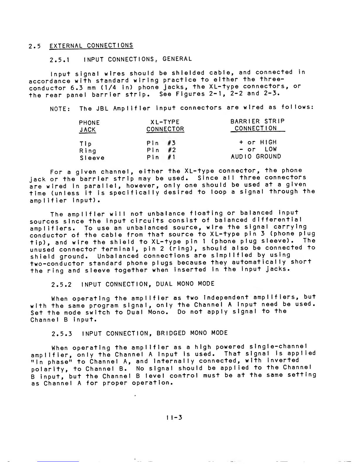
connections may be made via 3-pIn XL-type connector, three-cond uctor
(TRS) 6.3 mm (1/4 In.) phone Jack, or barrier strip. The barrier
strip has separate terminals for audio ground and chassis ground.
The rack ears and heatsink of the amplifier are made of high
grade aluminum extrusions; the chassis Is fabricated of heavy gauge
steel. All Internal components are easily accessible through
removal of top and bottom panels. Front panel graphic details are
Incorporated on the rear-side of apolycarbonate laminate which Is
virtually Indestructible.
1-1

The five-way output binding posts are arranged in a 19 mm (3/4
in.) array so that bridged as well as normal connections may be made
with standard dual banana plugs, bare wire, or terminal lugs.
1.1 SPECIFICATIONS
OUTPUT POWER;
Rated Power
20 Hz-20 kHz Midband Power
1kHz
8-ohm stereo
(per channel) 300 W400 W
4-ohm stereo
(per channel) 600 W700 W
16-ohm bridge 600 W700 W
8-ohm bridge 1200 W1350 W
Rated Power is minimum continuous sine wave output per channel,
with both channels driving their rated load over apower bandwidth
of 20 Hz to 20 kHz. Maximum total harmonic or intermodulation
distortion measured at any power level from 250 milliwatts to rated
power is less than 0.1? for 8ohm stereo and 16 ohm bridge, 0.2?
for 4ohm stereo and 8ohm bridge.
Midband Power is maximum output power at onset of clipping, both
channels driven with 1kHz sine wave, THD 1?.
TRANSIENT INTERMODULATION DISTORTION: .03? max at rated output.
FREQUENCY RESPONSE; +0, -1 dB, 20 Hz to 20 kHz, at any level up to
rated output.
NOISE; At least 100 dB below rated output (15.7 kHz noise band-
width A-we ighted .)
INPUT: Balanced bridging differential amplifier.
INPUT IMPEDANCE;
Stereo Mode; 40k ohms used as balanced input; 20k ohms used as
unbalanced (single-ended) input.
Bridged Mono and Dual Mono Modes: 20k ohms used as balanced
input; 10k ohms used as unbalanced (single-ended)
Input.
MAXIMUM INPUT LEVEL: +20 dB* (7.75 VRMS).
INPUT SENSITIVITY; 1.1 Vfor rated output into 8-ohm load.
^In these specification^, where dB FeTeTs to aspecific level ,the
0dB reference is 0.775 volts RMS unless otherwise noted.
1-2

VOLTAGE AMPLIFICATION: Variable; maximum 33 dB.
RISE TIME: Less than 7microseconds.
SLEW RATE: 50 V/m 1crosecond Into 8-ohm load.
DAMPING FACTOR: With 8-ohm load, greater than 200 at any frequency
from 20 Hz to 1kHz.
CHANNEL SEPARATION: Greater than 60 dB at 1kHz.
POLARITY: Output signal Is In phase with pin 3of XL-type connector,
tip of 6.3 mm (1/4 In.) phone jack and the barrier strip
•' +"terminal.
AC POWER: Typical AC power consumption.
At Idle (approx. )120 W
At rated output 1400 W
Both channels 8-ohms
At rated output 2000 W
Both channels 4-ohms
DC OUTPUT OFFSET: ^10 millivolts maximum.
DIMENSIONS: 178 X483 mm
(7 X19 In.)
DEPTH:** 356 mm
(14 In.)
NET WEIGHT: 28.58 Kg.
(63 lbs.)
SHIPPING WEIGHT: 33.11 Kg.
(73 lbs.)
OPTIONAL ACCESSORIES: Attenuator security cover.
PROTECTION CIRCUITRY: The amplifier outputs are protected against
short circuits and are stable Into reactive
loads. Short circuit protection Is clean with
no degrading characteristics. The loudspeakers
are protected against amplifier failure by 2
Internal relays that ground the load If excess
DC voltage Is detected at the output or upon
ITS Al low“a“ml nImum of 51 mmT2 In.) behind amplifier for connections.
1-3

CONTROLS :
IND ICATORS
CONNECTORS
Input:
Ground
:
Output;
Power
;
failure of apower supply. If the amplifier
overheats, the relays open until the amplifier
has cooled down. The relays are activated at
turn on and turn off to prevent thumps In the
loudspeaker during system power up/down.
Independent detented level controls. Heavy-duty Illumin-
ated rocker-type power switches. Recessed stereo/dual
mono/brIdged mono mode switch located on rear panel.
:Individual channel clip and standby Indicators. ’•STANDBY"
Indicates action of output relay.
3-pIn XL-type 3conductor, 6.3 mm (1/4 In.) phone jacks,
and barrier strip. May be wired balanced or unbalanced.
Chassis ground and audio ground connected with removable
shorting strap on rear panel barrier strip.
Color coded 5-way binding posts on 19 mm (3/4 In.) centers.
1.5 m(5-foot) 3-wIre AC power cord with U-ground male
connector
.
1-4

SECTION II
INSPECTION AND INSTALLATION
2.1 UNPACKING AND INSPECTION
Your JBL Power Amplifier was carefully packed at the factory,
and the container was designed to protect the unit from rough
handling. Nevertheless, we recommend careful examination of the
shipping carton and Its contents for any sign of physical damage
which could have occurred In transit. If damage is evident, do not
destroy any of the packing material or the carton, and Immediately
notify the carrier of apossible claim for damage. Shipping claims
must by made by the customer.
Save the carton and packing material In the event the unit must
be returned for service. See Section 5.2, ’’Repairs and Warranty,”
for Instructions on returning aunit.
2.2 ENVIRONMENTAL CONSIDERATIONS
The amplifier will operate satisfactorily over arange of
ambient temperatures from 0“C to +50*C (+32*F to 122*F), and up to
80$ non-condensing relative humidity.
If the amplifier Is Installed in an equipment rack, adequate
ventilation must be provided In order to assure longest component
life. Additional heat-producing devices should not be placed
directly above or below the amplifier, but at least 1-3/4” away.
Keep any obstructions such as wire bundles and rear mounted
connector panels away from fan Intake area. Again, do not mount
other products above or below the amplifier In such away that would
block off air flow to heatsink area. It is normal for the amplifier
front panel and rack ears to become warm during operation since it
Is part of the heatsinking system of the amplifier. See Section
3.2.1, anote on amplifier cooling.
Since the amplifier is quite heavy, be sure the rack is capable
of supporting it. When arack is to be transported with aportable
sound system, the amplifier should be supported from the rear and
from below; afew pieces of angle Iron secured to the sides of the
rack should suffice. It is also recommended that the amplifier be
placed low in the rack to minimize any tendency for the rack to tip
over.
2.3
AC POWER
All JBL Power Amplifiers shipped to points in the USA and
Canada are wired for 120 VAC 60 Hz operation. Amplifiers wired for
operation on any other voltage are identified as such with asticker
on the rear panel and atag attached to the amplifier power cord.
I1-1

WARNING
BE SURE TO VERIFY BOTH THE ACTUAL LINE VOLTAGE AND THE
VOLTAGE FOR WHICH THE AMPLIFIER HAS BEEN WIRED BEFORE
CONNECTING AC POWER. APPLICATION OF EXCESSIVE VOLTAGE TO
THE POWER SUPPLY MAY RESULT IN EXTENSIVE DAMAGE WHICH IS
NOT COVERED BY THE WARRANTY.
To comply with most electrical codes this amplifier is supplied
with athree-conductor AC power cable, the grounding pin of which is
connected to the chassis. In some instal lations this may create
ground loop problems when an AC potential exists between conduit
ground and audio ground. This will be evidenced by hum or buzz in
the amplifier output. If this should occur please refer to Section
2.9 for suggestions. Proper grounding of the amplifier Is important
for both noise and safety reasons. Be aware that unless the
amplifier is properly grounded, asafety hazard can exist. JB
L
accepts no responsibility for legal actions or for direct, indirect
or consequential damages that may result from violation of
eIectr ica Icodes
.
2.4 AMPLIFIER MODE SWITCH
Arecessed switch on the rear panel provides for convenient
change of amplifier mode from stereo, dual mono, and bridged mono
output. The functions are as follows:
STEREO;
Independent channel operation.
DUAL MONO:
To feed both channels of the amplifier with the same
input signal, the dual mono mode eliminates the need for a
patch cord. The input connector goes to Channel A. The signal
is internal ly routed to Channel Aand Channel B, with both
level controls active. There is no connection to Channel B
Input.
BRIDGED MONO:
This mode combines the power of both channels into a
single mono amplifier. Input is to Channel A. Level control
is by Channel Aand Channel B, and output is taken from the red
binding posts of Channels Aand Bas described In Section
2.5.5. IMPORTANT; BOTH LEVEL CONTROLS MUST BE AT SAME SETTING
FOR PROPER OPERATION.
I1-2

2.5 EXTERNAL CONNECTIONS
2.5.1 INPUT CONNECTIONS, GENERAL
Input signal wires should be shielded cable, and connected in
accordance with standard wiring practice to either the three-
conductor 6.3 nm (1/4 In) phone jacks, the XL-type connectors, or
the rear panel barrier strip. See Figures 2-1, 2-2 and 2-3.
NOTE: The JBL Amplifier Input connectors are wired as follows;
phone XL-type barrier strip
jack connector connection
Tip Pin #3 +or HIGH
Ring Pin #2 -or LOW
Sleeve Pin #1 AUDIO GROUND
For agiven channel, either the XL-type connector, the phone
Jack or the barrier strip may be used. Since all three connectors
are wired in parallel, however, only one should be used at agiven
time (unless it is specifically desired to loop asignal through the
amp IIfier 1nput)
.
The amplifier will not unbalance floating or balanced Input
sources since the input circuits consist of balanced differential
amplifiers. To use an unbalanced source, wire the signal carrying
conductor of the cable from that source to XL-type pin 3(phone plug
tip), and wire the shield to XL-type pin 1(phone plug sleeve). The
unused connector terminal, pin 2(ring), should also be connected to
shield ground. Unbalanced connections are simplified by using
two-conductor standard phone plugs because they automatically short
the ring and sleeve together when inserted In the input jacks.
2.5.2 INPUT CONNECTION, DUAL MONO MODE
When operating the amplifier as two independent amplifiers, but
with the same program signal, only the Channel Ainput need be used.
Set the mode switch to Dual Mono. Do not apply signal to the
Channel Binput.
2.5.3 INPUT CONNECTION, BRIDGED MONO MODE
When operating the amplifier as ahigh powered single-channel
amplifier, only the Channel Ainput is used. That signal is applied
"in phase" to Channel A, and internally connected, with inverted
polarity, to Channel B. No signal should be applied to the Channel
Binput, but the Channel Blevel control must be at the same setting
as Channel Afor proper operation.
I1-3

2.5.4 FIVE-WAY BINDING POST OUTPUT CONNECTORS
Five-way binding post outputs have been chosen because they
allow connections to be made quickly, they facilitate polarity
reversals for speaker "phasing,” and they can handle high current
with agreat margin of safety. See Figure 2-4.
The preferred connection method Is to use adual banana plug
for each speaker cable. Simply Insert each plug Into the corres-
ponding channel's red and black binding posts. See Figure 2-5.
In the absence of adual banana plug (or two single banana
plugs), loosen the plastic terminal nut, wrap the stripped and
twisted wire end clockwise around the terminal, and secure It by
tightening the nut.
NOTE; Tin the wire ends with solder to prevent unraveling,
but avoid excess solder as it can promote cable breakage.
Smaller speaker cable can be pushed through the hole In the
binding post shaft, but we recommend heavier gauge cables to
wrap around the shaft.
If a lug Is Installed on the cable, loosen the terminal nut,
push one "leg" of the lug through the hole In the shaft, and tighten
the nut.
2.5.5 ABOUT OUTPUT POLARITY AND BRIDGED MONO CONNECTION
In normal stereo operation (or dual mono), apositive-going
signal applied to pin #3, the phone jack tip, or the +terminal of
the barrier strip will cause apositive-going signal to appear at
the red output binding post of that channel.
In bridged mono operation the two amplifier channels are driven
from the Channel AInput, but Channel BIs Internally reversed In
polarity. The speaker Is connected between the two red binding
posts (the black posts are not used In bridged mono mode). In this
case, apositive-going signal applied to the Channel AInput appears
as apositive-going signal at the Channel Ared binding post and as
anegative-going signal at the Channel Bred binding post. See
Figure 2-6.
NOTE: The two channels' binding posts are clustered to
facilitate mono connection across the red posts with astandard
dual banana plug. DO NOT CONNECT THE TWO RED BINDING POSTS TO
EACH OTHER, and DO NOT GROUND EITHER SIDE OF THE OUTPUT IN
BRIDGED MONO MODE.
2.6 INPUT IMPEDANCE AND TERMINATION
Audio engineering has Its roots In the telephone Industry, and
I1-4

"600 ohm circuits" (together with their predecessors, "500 ohm
circuits") are carry-overs from telephone transmission practices.
Long audio transmission lines, like their video counterparts, must
be properly sourced from and terminated in equipment which matches
their character ist icimpedance if optimum frequency response and
noise rejection are to be achieved.
However, transmission line theory and techniques are not only
unnecessary but impractical within modern recording studios, broad-
cast studios and other local audio systems where transmission
circuits are seldom more than several hundred feet in length. The
advent of negative feedback circuitry and solid-state electronics
has spawned modern audio amplifiers and other signal processing
devices having source impedances of only afew ohms. They are
essentially indifferent to load impedances and, by varying their
output current inversely to changes in load impedance, maintain the
same output voltage into any load Impedance above arated minimum,
with no change in frequency response.
Modern audio systems, therefore, utilize amplifiers and other
active devices which have very low output impedances and high (10k
to 50k ohm) Input impedances. These products may thus be cascaded
(operated in series), or many inputs may be connected to asingle
output of apreceding device, without regard to impedance matching.
Switching and patching is simplified because double loads and
unterminated bugaboos are essentially eliminated. Floating
(ungrounded) transformer outputs minimize ground loop problems, and
differential transf ormer Iess input circuitry (or input transf ormers)
minimize common mode noise or interference which may be induced into
the interconnecting wires or cables.
Where audio must be transmitted through cables or wire pairs of
more than several hundred feet in length, however, transmission line
termination practices should still be observed.
This amplifier has input impedances of 40,000 ohms when used in
abalanced, differential input configuration, and 20,000 ohms when
used unbalanced (one side grounded). This makes the amplifier
suitable for use with any normally encountered source impedance, low
or high. Therefore, there are only two situations which will
require an input load at the amplifier;
1) when the source requires a600 ohm load, such as apassive
equalizer, older vacuum tube equipment, etc.
2) when the source is atransmission line such as atelephone
line.
In some Instances it may prove beneficial to treat the
input feed to the power amplifier as atransmission line
to lower its impedance and its susceptibility to noise
pickup
.
I1-5

Input load resistors, If required, may most conveniently be
attached to the barrier strip connector of the amplifier.
2.7 APPROPRIATELY RATED LOADS
2.7.1 IT IS THE USER’S RESPONSIBILITY TO AVOID OVERPOWERING
It is essential that the amplifier be used with loudspeakers of
suitable impedance that can handle the amplifier’s power output. We
realize this Is not always easy to determine, especially since
speaker power ratings have not been standardized. Nonetheless, JBL
IS NOT RESPONSIBLE FOR DAMAGE TO LOUDSPEAKERS RESULTING FROM
OVERPOWERING.
Fuses may be Inserted in series with the loudspeaker to protect
against overpowering, though the fuse value must be chosen with
care. Ideally, the value will be high enough that the fuse does not
limit the peak power capability of the loudspeaker. On the other
hand, the fuse value must be low enough for the fuse to actually do
its job. It takes aperiod of time to heat the fuse element enough
to cause it to melt and break the circuit. If it takes too long,
the loudspeaker may go first. Obviously, delayed action (slo-blo)
fuses are not acceptable for use here. If fuses are used, consider-
ation must be given to their location. Put them where they are
accessible for ease of replacement, provide clear labelling of the
replacement fuse value, and place spare fuses nearby.
2.7.2 MORE ABOUT LOUDSPEAKER POWER RATINGS
While there is no cut-and-dr ied method to establish an
appropriate amplifier power for agiven speaker system, certain
guidelines do exist. If aloudspeaker manufacturer specifies ’’to be
used with amplifiers rated at no more than ’x’ watts," then neither
speaker nor amplifier warranty is likely to cover damage if alarger
amplifier is used. If the amplifier power Is only recommended, or
if apower rating is given without mentioning the amplifier, then the
question as to whether the amplifier is "safe" becomes more difficult
to answer.
Loudspeakers usually fail due to one of two factors: thermal or
mechanical overload. Thermal overload means overheating, and is
almost always caused by applying too high alevel of sustained,
average power; the voice coll insulation may burn and short circuit,
the coil may deform due to the heating and scrape in the gap, and. In
some cases, speaker cones have been known to burst into flame.
Mechanical overload means excessive d1aphragm/vo 1ce coll travel. A
single very high power transient, especially at lower frequencies,
can literally tear aloudspeaker apart. Sometimes mechanical over-
load Is more gradual, with the voice coll "bottoming" against the
magnetic assembly until It Is deformed; acompression driver dia-
phragm can strike the phase plug and shatter, or the suspension can
be overextended and simply tear apart.
I1-6

In order for manuf acturers to convey some real-world specifica-
tions about their products, they must have methods to attempt
simulation of real-world conditions. One often used method is to use
pink noise and/or white noise techniques. Pink noise is bandwidth
limited random noise, and is generally used as asimulation of
"average program power;" i.e. the average power contained in a
typical musical sequence, whereas white noise is not limited to any
specific bandwidth or curve and as such, contains more high frequency
energy. These two test the thermal overload character Ist Ics of the
device. Another test method is to sweep asine-wave through part or-
al Iof the audio spectrum. While this method may cause less thermal
overload than the pink or white noise method. It can cause larger
excursions, particularly at low frequencies. This is agood test of
the mechanical overload characteristics. With compression drivers,
the mechanical power handling capability is approximately quadrupled
simply by raising the minimum crossover frequency by an octave. If
any conclusion can be drawn, it is this:
NO SINGLE POWER RATING REALLY DESCRIBES THE POWER HANDLING
CAPABILITY OF ANY LOUDSPEAKER OR LOUDSPEAKER SYSTEM. ALSO,
WHEN ALOUDSPEAKER SYSTEM IS MULT I-AMPL IFIED ,I.e. AHIGH
FREQUENCY DRIVER IS CONNECTED DIRECTLY TO THE POWER AMP-
LIFIER OUTPUT, ASERIES PROTECTION CAPACITOR IS STRONGLY
RECOMMENDED TO REDUCE THE POSSIBILITY OF ACCIDENTAL DAMAGE
TO THE DRIVER DIAPHRAGM. CONSULT THE MANUFACTURER OF THE
DRIVER AND HORN FOR RECOMMENDATIONS ON PROTECTION CAPACITOR
TYPES AND VALUES.
2.7.3 SOMETIMES ALARGER AMPLIFIER CAN BE SAFER
If the desired sound level is high enough to require alow
power amplifier to be operated into clipping more than occasionally,
it may be safer to use alarger amplifier that will clip less
frequently. In asmall amp which Is clipping, the average output
power rises due to the increased signal density caused by distortion
components. This increases thermal and mechanical stress in the
speaker because the clipped waveforms place greater "G" loads on the
moving parts, and large amounts of high frequency harmonics are
generated which can destroy the tweeter voice coils.
Amore powerful amplifier which is able to generate the desired
peak sound level without clipping avoids the large increase In
average power (thermal) and the high acceleration (mechanical)
stresses caused by the small amplifier. The major drawback of the
larger amplifier Is that it can produce higher peak outputs that may
instantly destroy aloudspeaker. Great care must be exercised to
ensure that the amplifier will not be driven at too high alevel,
certainly never into clipping. This can be accomplished either by
knowing the program material (if recorded) and setting levels
accordingly, or by using peak limiters (with live or unknown program
mater iaI)
.
I1-7

2.7.4 REMEMBER THE DIVIDING NETWORK (CROSSOVER)
If the amplifier Is connected to amulti-way loudspeaker system
that Includes apassive, high-level dividing network (crossover), be
sure the network Is rated to handle the amplifier's power. Pre-
packaged speaker system power ratings already take the crossover
Into account.
If you obtain separate components and assemble asystem, the
chances are that the higher frequency drivers will be rated at less
power than the woofer(s). This works out overall because the higher
frequency drivers tend to be more efficient (more sound per watt).
In fact, higher sensitivity In the high frequency components usually
requires some attenuation to be applied In the dividing network. A
3dB more sensitive driver must be driven with half the power to
generate the same sound level.
For example, consider atypical two-way system with a200 watt
woofer and 50 watt high frequency compression driver. The woofer, 1
meter from Its enclosure, generates 100 dB SPL with 1watt at Its
Input, and the compression driver, 1meter from Its horn, generates
106 dB SPL at 1watt input. If both components are driven by a200
watt program signal, the compression driver will be 6dB too loud
(four times the level of the woofer). Therefore, the crossover
network must provide 6dB of attenuation for the compression driver,
lowering Its Input power to 50 watts. The 200 watt amplifier turns
out to be perfectly suited to driving this system, even though one
driver Is rated at just 50 watts.
2.8 SPEAKER CABLES
2.8.1 TYPE OF WIRE
Anumber of companies offer various special ’’speaker cables”
which are claimed to vastly Improve the signal delivered from
amplifier to loudspeaker system. Some special cables have merit,
others may actually be detrimental, and the value will have to be
determined by the user. For most applications two factors need to
be considered; DC resistance and durability.
Generally, the larger the wire gauge, the better. DC resis-
tance is lower with larger wire, more of the amplifier power gets to
the loudspeaker, and damping factor Is not degraded. More strands
of wire In agiven wire gauge are beneficial because they let the
cable handle more flexing without fatigue.
2.8.2 DAMPING FACTOR
The higher the damping factor of an amplifier, the greater Its
ability to control unwanted speaker cone movements -- especially at
low frequencies. To understand how ahigh damping factor Improves
sound quality, you must first understand some basic principles.
I1-8

When asignal drives awoofer, current flowing through the
voice coll creates amagnetic field. This field Interacts with the
permanent magnetic field In the gap and forces the dIaphragm/vo Ice
coll assembly to move outward. When the signal Is removed, the
dIaphragm/ VO Ice coll assembly begins to move Inward, but Its
momentum causes It to overshoot Its resting point. This overshoot
will eventually damp Itself out, but you can see how unwanted cone
movements are generated.
After signal Is removed and the voice coll Is moving Inward
through the magnetic field. It generates acurrent of opposite
polarity to the original signal. This current Induces avoltage or
"back EMF" which travels through the speaker wire to the amplifier's
output and through the amplifier to ground. The lower the amplifier's
output Impedance, the better the damping action on the voice coll.
The result of ahigher damping factor Is more accurate reproduction of
bass and lower midrange frequencies.
The theoretical damping factor of an amplifier may not be
realized at the speaker due to added Impedance of the cable.
^
Larger gauge cables not only reduce signal losses, but they Increase
damping factor when long lengths are used.
To calculate damping factor, divide the speaker's rated
Impedance by the amplifier's output Impedance. For example, an
amplifier with 0.04 ohms output Impedance (assuming no cable losses)
at 1kHz would have adamping factor of 200 to an 8ohm speaker (8 /
0.04 =200) .
2.8.3 CALCULATING LOSSES IN SPEAKER CABLE
WIRE
DIAM.
(mm
)
SOLID
A.W.G.
WIRE
GAUGE
DC RESISTANCE
PER 30 m(100 ft)
OF TWO-CONDUCTOR
CABLE (OHMS)
CABLE LENGTH
PRODUCE AONEWHICH WILL
dB POWER LOSS
@FOUR
meters ohms
feet &EIGHT ohms
meters feet
366 1200 740 2425
244 800 488 1600
145 475 290 950
91 300 183 600
58 190 114 37 5
37 120 73 240
23 75 46 150
15 50 30 100
930 18 60
4.115
3.264
2.588
2.05
1.63
1.29
1.02
0.813
0.643
6
8
10
12
14
16
18
20
22
0.08
0.13
0.20
0.32
0.52
0.82
1.32
2.08
3.30
POWER LOSSES IN SPEAKER CABLES
This chart may be consulted to establish the approximate power
loss (and damping factor degradation) for various wire gauges.
I1-9

2.9 GROUND ING
For safe operation the amplifier must be connected to agood
mechanical ground. This provides for acurrent path for any voltage
which should appear on the chassis due to afault In the amplifier.
This current path will result In blowing the main power supply fuse.
Without this current path, the amplifier would present ashock
hazard. In addition, agood quality ground on the chass Isprov Ides
shielding from external fields and minimizes radiation of Internal
fields to the outside world. To comply with safety regulations In
many localities and to protect our customers, we provide aground
connection through the 3-wire electrical cord. There are afew
Instances where ahum or buzz will be noticed In the amplifier
output. This Is caused by avoltage potential between the audio
ground from the previous piece of equipment and the mechanical
ground to which the amplifier has been connected, and is called a
"ground loop."
If this Is the case, the first attempt at asolution should be
to remove the strap on the rear panel barrier strip which connects
audio ground and chassis. Audio ground will then be referenced from
the signal source and not the chassis of the amplifier. The next
thing to try Is a3prong to 2prong AC adaptor between the power
cord and the power outlet, to temporarily unground the amplifier.
Try the amplifier with and without the ground strap on the barrier
strip to determine which connection works best. Remember ,however,
that for safety you must still have aconnection to chassljs ground.
This is normally made through aproperly grounded third pin connec-
tion, or can be accomplished by tying all chassis’ within arack
together with aheavy (#10 or larger) wire, then connecting this
wire to the cold water pipe ground.
2.10 SECURITY COVERS
In some Installations It may be necessary to safeguard the
amplifier gain control settings. The Model 6200SC Security Cover Is
available and contains enough covers for six amplifiers. Installa-
tion instr uct Ions:
1) Remove the two Level control knobs. If they are on too tight to
be removed by fingers, use apair of long nose pliers to grasp
the bar on the knob and pull outwards. Wrap the jaws of the
pliers with masking tape to prevent scratching of the knob.
2) If necessary, adjust the gain controls using asmall screwdriver.
3) Press each of the security covers Into the hole until It snaps
firmly into place.
To remove the cover, slip your fingernail under the edge of the
cover and pry it up and off. Alternately, asmall screwdriver or
knife blade may be used, taking care not to scratch the front panel.
I1-10

IMPORTANT: DO NOT POKE YOUR FINGERS OR METAL TOOLS INTO THE
AMPLIFIER WHEN THE KNOBS ARE OFF. THERE IS THE POSSIBILITY OF
SEVERE SHOCK HAZARD DUE TO THE HIGH VOLTAGE/HIGH CURRENT DC USED TO
POWER THIS DEVICE. THE AMPLIFIER SHOULD ONLY BE OPERATED WITH THE
KNOBS OR SECURITY COVER IN PLACE.
high
low
shield
#3
#2
n
tip
ring
sleeve
FIGURE 2-1. BALANCED INPUT CONNECTIONS*
Input Signal
high
low
shield
high
low
shield
#3
#1,2
tip
sleeve
FIGURE 2-2. UNBALANCED INPUT CONNECTIONS*
*For agiven channel, use either XL-type or phone jack, not
both. For mono operation, use only Channel A.
11-11

Balanced Connection
Chassis
Ground
FIGURE 2-3. BARRIER STRIP CONNECTIONS
I1-12

FIGURE 2-4. USE OF FIVE-WAY BINDING POSTS
FIGURE
CHANNEL ACHANNEL B
RED
a£
BLACK
2-5. OUTPUT CONNECTIONS TO TWO CHANNEL SPEAKER SYSTEM
CHANNEL A
RED
BLACK
BINDING POSTS
NOT USED
FIGURE 2-6. BRIDGED OUTPUT CONNECTION TO MONAURAL SPEAKER SYSTEM
Table of contents
Other JBL Amplifier manuals