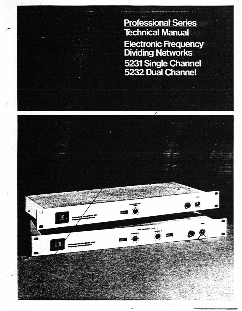
JBL 5233 Manual

ProfessionalSeries
Installationand
ServiceManual
ElectronicFrequency
DividingNetworks
5233SingleChannel
5234DualChannel

OWNER'S
INSTRUCTIONS
WARNING—
Topreventfireorshockhazard,donotexposethisapplianceto
rainormoisture.
JBLcontinuallyengagesinresearchrelatedtoproductimprovement.
Newmaterials,productionmethodsanddesignrefinementsareintro-
ducedintoexistingproductswithoutnoticeasa routineexpressionof
thatphilosophy.Forthisreason,anycurrentJBLproductmaydifferin
somerespectfromitspublisheddescriptionbutwillalwaysequalor
exceedtheoriginaldesignspecificationsunlessotherwisestated.
Specifications
Gain0 dBinthepassband
RatedOutput6.2V (+18dBref.0.775V)
DistortionLessthan0.5%THD,20-20,000Hz
atratedoutput
Lessthan0.2%THD,20-20,000Hz
at+10dBref.0.775V
FrequencyResponse±0.5dB,20-20,000Hz
CrossoverFrequencySelectablebyplug-inmodule,
3dBcrossoverpoint±10%
FilterSlope12dBor18dBperoctave
InputImpedance-.Greaterthan50kfl
LoadImpedance600O orgreater
OutputImpedance47fi
ChannelIsolationGreaterthan60dB,20-20,000Hz
Signal/NoiseRatioGreaterthan90dB,20-20,000Hz
equivalentbandwidth
ControlsHighFrequencyLevel(eachchannel)
SupplyVoltageSelect
PowerRequirement5 W 120/240V AC,50/60Hz
OperatingTemperatureUpto55°C(132°F)
Dimensions44mmx 483mmx 194mmdeep
1%
x 19x 7%indeep
:Mounting1 EIAstandardrackspace
PanelFinishSemi-glossnon-glarebakedenamel,
darkgray
NetWeight1.8kg(4lb)eitherunitwith
accessorycrossovercard(s)installed.
ShippingWeight3.0kg(6.5lb)eitherunit
:Accessories
CrossoverCards51-5130BlankCard,Unloaded18dB/Octave
I(onerequired51-5132500Hz18dB/Octave
perchannel)51-5133800Hz18dB/Octave
52-5120BlankCard,Unloaded12dB/Octave
52-5140For4343and4350StudioMonitors

Owner'sInstructions
The5233and5234aredesignedforusewithstudio
monitororsoundreinforcementloudspeakersystemswhere
bi-amplificationortri-amplificationisdesirable.The5233
[singlechannel]and5234(dualchannel)featuredifferential
highimpedanceinputs,unitygaininthepassband,and
unbalancedlowimpedanceoutputs.The5233willprovidea
singlechannelcrossover.The5234providestwoseparate
channelswithindependentcrossoveraction(asina stereo
installation).
Thepowerswitchandpilotlightfortheunitanda high
frequencylevelcontrolforeachchannelarelocatedonthe
frontpanelforeasyaccess.Thecrossoverfrequencyat
whicheachchannelisoperatingisindicatedthrougha front
panelwindow.A voltagechangeswitchislocatedontherear
panel.
EithermodelcanbemountedinoneEIAstandard
rackspace.
Crossovercardsareavailableformostcommonlyused
frequencies.Filterslopesare12dBor18dBperoctave
withhighandlowfrequencyoutputattenuated3 dBatthe
crossoverpoint.Cardsarealsoavailablewiththespecific
crossovercharacteristicsrequiredfortheJBL4343or4350
bi-amplifiedstudiomonitors.Inaddition,blankcardscanbe
obtainedforconstructionofcrossovernetworksforother
frequencies.
Installation
Theelectronicfrequencydividingnetworkreceivesthe
programsignalfroma linelevelsource-preamplifier,studio
console,orportablemixer-andseparatesthesignalinto
highandlowfrequencybands.Outputsfromthenetwork
feedtheappropriatepoweramplifiers,whichinturndrive
theirrespectiveloudspeakersystemcomponents.Input
connectionsmaybebalancedorunbalanced,output
con-
nectionsareunbalanced;shieldedcableisrequired.Ifoutput
cablelengthsaregreaterthan4.5to6 m (15to20ft),isolation
transformers(600ft: 600ft) arerecommendedateach
outputtoreducethepossibilityofradiofrequencyinterference
orhum.Theoutputscandeliver+18dB(6.2V into600ft)
andwilldrivethelineinputsofconventionalamplifiers.Two
ormorepoweramplifierscanbedrivenfromeachoutput.
The5234dualchannelnetworkcanbeusedtotri-amplify
aloudspeakersystembyconnectingthelowfrequency
outputofchannel2 totheinputofchannel1.(Twisttwo
unshieldedwirestogetheroruseshieldedcableforthis
connection.)Thechannel
1
outputscanthenbeusedtodrive
themidrangeandlowfrequencyamplifiers.Typicalinstal-
lationsarediagrammedinFigure1.
Whenevera midrangeorhighfrequencydriverisconnected
directlytoa poweramplifier,a seriescapacitorisrecom-
mendedtoattenuateunwantedlowfrequency"on-off"
switchingtransientsignalswhichcandamagethedriver.
Itispossibletoconstructa systemusinganelectroniclow
frequencytransitionanda conventionalpassivenetworkfor
themidrangeorhighfrequencycrossover.TheJBL4350
StudioMonitor,diagrammedinFigure2,issucha system.Ifa
pairof4350saretobeused,a single5234canaccommodate
bothsystems.Notethatthepassive,highlevelfrequency
dividingnetworksusedinallJ BLstudiomonitorsdesignedfor
bi-amplificationalreadyincorporatetherequiredattenuation
capacitorstoprotectthemidrangeandhighfrequency
drivers.
3

ConventionalPassiveNetworks
PROGRAM
SOURCE
ONE
AMPLIFIER
LOUDSPEAKERSYSTEM
PASSIVE
FREQUENCY
DIVIDING
NETWORK
LOUDSPEAKERSYSTEM
PROGRAM
SOURCE
ONE
AMPLIFIER PASSIVE
FREQUENCY
DIVIDING
NETWORKS
Two-WaySystem Three-WaySystem
ElectronicNetworks
PROGRAM
SOURCE LOUDSPEAKERSYSTEM
r
— 1
ACTIVE
FREQUENCY
DIVIDING
NETWORK
PROGRAM
SOURCE
ACTIVE
FREQUENCY
DIVIDING
NETWORK
HIGH
Two-WaySystemwithSingleChannelActiveCrossover Three-WaySystemwithDualChannelActiveCrossover
PROGRAM
SOURCE
PROGRAM
SOURCE
LOUDSPEAKERSYSTEM
Fig
u
re1.
Typical
Installations of the
5233
and
5234
Compared
to Conventional
Passive
Networks
4
HIGH
LOW
HIGH
MID
LOW
TWO
AMPLIFIERS
HF
LF
5233
HIGH
LOW
5234
THREE
AMPLIFIERS
LOUDSPEAKER
SYSTEM
LOW
HF
HF
LF
LF
FOUR
AMPLIFIERS
LOUDSPEAKERSYSTEM
HF
LF
HF
LF
CHANNEL
2
5234
CHANNEL
1
LOW
HIGH
HIGH
LOW
ACTIVE
FREQUENCY
DIVIDING
NETWORK
TwoIndependentTwo-WaySystemswithDualChannelActiveCrossover

LOUDSPEAKERSYSTEM
ACTIVE
FREQUENCY
DIVIDING
NETWORK
Figure
2.
Combining
Electronic
and
Passive
Frequency
Dividing Networks
Mounting
The5233
or
5234can
be
mounted
ina
single
EIA
standardrackspacewithoutadditionalbracing
or
ventilation.
Allexternalconnectionsaremadeontherearpanel.Mounting
hardware
is
suppliedwitheachunit.
Connections
Shieldedcable
is
necessary
for
allinputandoutput
connections.Makecertainthattheshield
is
properly
con-
nected,
as
shown
in
Figures
3
and
4.
Input connections-Inputs
to
the5233and5234are
fora
linelevelsource,balanced
or
unbalanced.Screwterminals
on
the
rearpanel
are
provided
for
connection
of
eachinput
andareclearlyidentified.Balancedconnectionsareshown
incolorexchanging
HI
and
LO
conductorswillresult
inphasereversal.
AMPLIFIER
PROGRAM
SOURCE
5233
PROGRAM
SOURCE
JAMPLIFIER
LOUDSPEAKER
SYSTEM
DualChannel
5234
ELECTRONIC
FREQUENCY
DIVIDING
NETWORK
AMPLIFIER
LOUDSPEAKER
SYSTEM
CHANNEL
1
1
LOUDSPEAKER
SYSTEM
CHANNEL
2
Figure
3.
Wiring Diagram
for
Bi-Amplification
PROGRAM
SOURCE
TWO
AMPLIFIERS
HF
LF
5233
ULTRA-HIGH
HIGH
MID
PASSIVEFREQUENCY
DIVIDINGNETWORK
5233
ELECTRONIC
FREQUENCY
DIVIDING
NETWORK
SingleChannel
HIGH
LOW
AMPLIFIER
AMPLIFIER
AMPLIFIER
HIGH
LOW
HIGH
LOW
PROGRAM
SOURCE
CHANNEL1
PROGRAM
SOURCE
PROGRAM
SOURCE
CHANNEL
2
5234

5234
ELECTRONICFREQUENCYDIVIDINGNETWORK
5234
PROGRAMSOURCE
(UNBALANCED)
PROGRAMSOURCE
(BALANCED)
Output
Connections
-Eachoutputchannelcandeliver
6.2V into600Q orgreater(+
18
dBref.0.775V}.A separate
pairofscrewterminals,locatedontherearpanel,isprovided
forthelowandhighfrequencyoutputofeachchannel.
Outputswilldrivethelineinputofanyconventionalamplifier.
Typically,theimpedanceofa bridginginputisatleast5 kn
(usually10knormore);thereforetwoormorepower
amplifierscanbedrivenbya singleelectronicfrequency
dividingnetwork.
Operation
VerificationofSystemWiring
Itisimperativethateachoutputoftheelectronic
frequencydividingnetworkbeproperlyconnected.
Inadvertentexchangeoflowandhighfrequencyoutput
connections—atthenetwork,poweramplifiers,ortrans-
ducers—mayresultinseveredamagetomidrangeorhigh
frequencyloudspeakersystemcomponents.
Thefollowingprocedureshouldbefollowedforeach
programchannelpriortooperation.
1.
Withallpoweroff,settheHighFrequencyLevelcontrol
at"2"andadjusttheprogramsourceleveltominimum
(Thesourcematerialmaybewidebandnoiseormusic.)If
thepoweramplifiersareequippedwithlevelcontrols,adjust
themtoapproximatelyonequarterpower.
2.
Turnontheprogramsource,network,andamplifiersfor
thechannelundertest.
3.Graduallyincreasetheprogramsourcevolumeleveluntil
audible.Ifthesoundcomesmainlyfromthemid-rangeor
highfrequencydriver,shutpoweroffimmediatelyand
AMPLIFIER
AMPLIFIER
checkallwiring.Ifthelowfrequencyloudspeakerproduces
bass,
graduallyadvancetheHighFrequencyLevelcontrol.
Correctsystemwiringwillbeverifiedifthetreblecompo-
nentoftheprogrammaterialincreasesinlevelwhile
comingsimultaneouslyfromthemidrangeandhigh
frequencydrivers.
TransducerPhasing
Oneimportantfactorinthenaturalsoundcharacter
ofa loudspeakersystemisthephaserelationshipofthe
transducersforanoctavebelowandaboveeachcrossover
frequency.Twosuitablemethodsforestablishingproper
phaseofthecomponentsina two-waysystemaredescribed
inthefollowingparagraphs.Eitheronemaybeused,depend-
ingontheavailabilityoftestequipment.A three-orfour-way
systemshouldbetreatedina similarmannerbyfirstestab-
lishingtheproperphaseforthetransducersofthelow
frequencytransitionandthenprogressingtothemidrange,
highfrequency,orultra-highfrequencytransducers,as
applicable.
Objective
Method-A realtimethirdoctaveanalyzer,
condensermicrophone,anda pinknoisesourcecanbe
usedtoestablishproperphaseoftheloudspeakersystem
componentsasfollows:
1.
Usingpinknoiseasprogrammaterial,adjustsystem
volumeforcomfortablelisteningandsetthelevelsofthe
individualtransducerstodisplayflattestoverallfrequency
responseontherealtimeanalyzer.
2.
Reversepolarityofthehighfrequencydriverandobserve
theeffectonfrequencyresponsethroughthecrossover
region.
Properphasingofthetransducersisindicatedby
theflattestfrequencyresponsethroughthecrossover
regionasshownontherealtimeanalyzer.
6
AMPLIFIER LOUDSPEAKERSYSTEM
HIGH
MID
LOW
Figure4.Wiring Diagram forTri-Amplification
Shieldedcableisnecessaryforallinputandoutputconnec-
tions,
asshown.Makecertainthattheshieldisproperly
connectedtothegroundterminal.

Subjective
Method— Iftestinstrumentationisnotavailable,
properresultscanbeobtainedasfollows:
1.
Adjustvolumelevelforcomfortablelisteningandset
approximatesystembalanceusingpinknoiseorthenoise
heardbetweenstationsofanFMtuner.
2.
Listentoa recordingofa malevoicelongenoughto
becomeaccustomedtotheperformanceofthe
loud-
speakersystem.
3.Reversepolarityofthehighfrequencyloudspeaker,which
willproducea changeinvoicecharacter.Whenthetrans-
ducersareproperlyphased,a recordedmalevoiceshould
soundnaturalandexhibitpresence[oran"upfront"
quality],
incontrasttotheundesirable"hollow"sound
heardwhentransducersareoutofphase.
Note:
Ifthecrossoverfrequencyliesabove2 kHz,reversing
polarityofthehighfrequencycomponentwillcreatelittle
(ifany)perceptibledifferenceinsystemperformance.The
"correct"polarityinsucha casewillbethatwhichyields
themostnaturalqualitywitha varietyofprogrammaterial.
Onceproperphaseamongthetransducersofa
loud-
speakersystemhasbeendetermined,otherloudspeaker
systemsintheinstallation(assumingtheyarethesame
model]maybephasedaccordingly.Ifdifferentloudspeaker
systemsareused,establishcommonphaseamongthelow
frequencydriversandfollowtheaboveproceduresfor
eachsystem.
LovolControlAdjustment
Inmostinstances,manufacturersofmulti-amplified
loudspeakersystemsprovideinstructionsforbalancinglevels
oftheindividualdriversofthesystem.Intheabsenceof
formalinstructions,orinthecaseofcustomloudspeaker
systems,balancecanbeestablishedbyadjustinglevelsto
achievetheflattestresponseona realtimeanalyzer,as
describedabove,oronthebasisofsubjectiveevaluationof
familiarprogrammaterial(or,moreaccurately,byusingpink
noiseorthenoisebetweenFMstations]asdescribedinthe
followingparagraphs.
Eachprogramchannelshouldbeadjustedindividually;
subjectiveevaluationshouldbemadewhileseatedinthe
normallisteninglocation.Ifsubjectiveanalysisistobeused,
andthepoweramplifiersareequippedwithlevelcontrols,
initiallyadjustthecontrolstoonehalfoftheirfullrotation
andthenregulateasnecessary.
Subjective
Adjustment of Bi-Amplified
Systems—The
followingappliestoa 5233ortoeachchannelofa 5234used
indualchannelbi-amplification.
(
2.
Rotatethenetworkcontrolclockwiseuntila satisfactory
highfrequencybalancehasbeenobtainedintheprogram
material.
Ifnecessary,trimsourceoramplifierlevels.
Subjective
Adjustment of Tri-Amplified
Systems-When
bothchannelsofa 5234areusedfora tri-amplified
loud-
speakersystem,itisgenerallyinstalledsothattheChannel1
levelcontrolregulatestheoutputofthemidrangedriver
andtheChannel2 levelcontrolgovernsonlythehigh
frequencydriver.
1.
WithbothHighFrequencyLevelcontrolsat"0','adjustthe
sourcelevelforcomfortablelistening.
2.
RotatetheChannel1 levelcontrolclockwiseuntila
satisfactorymidrangelevelhasbeenobtainedinthepro-
grammaterial.Ifnecessary,adjustsourceoramplifierlevels
asappropriate.
3.IncreasetheChannel2 leveluntila satisfactoryhigh
frequencybalancehasbeenobtained.Itmaybenecessary
toreadjustmidrange,source,oramplifierlevelstoachieve
themostdesirableoverallbalanceoftheloudspeaker
system.
Oncehighfrequencyandamplifieroutputlevels
havebeenestablished,readjustmentisnotgenerally
needed.
Somemethodofmarkingorlockingthepower
amplifierlevelcontrolsisrecommended.
1.
WiththeHighFrequencyLevelcontrolat"0"adjustprogram
sourcelevelforcomfortablelistening.
7

8

ServiceInstructions
Thedividingnetworksareshippedwitha 52-5120cross-
overcardwithtwo1000ohmresistorsinstalledineach
channel,
asinFigure5.Thiscardconvertseachchannelinto
aone-input,two-outputunitygaindistributionamplifier.Two
ofthesespeciallyloadedcardswillconvertthe5234totwo
independentdirectamplifiers,eachhavingoneinputandtwo
outputs,orthenetworkinputscanbeparalleledtoprovide
fouroutputsfroma singlesource.The"highfrequency"
channelwillbeatunitygainwhenthelevelcontrolissetat
maximum.Thecontrolcanbeturneddowniflossisdesired.
The52-5120crossovercardmustberemovedbefore
installingthefrequencyselectioncardneededforthepartic-
ularapplication.Toinstalla newcrossovercard
1.
Placethe5233or5234upsidedownona softsurface,
removethetwoPhillips-headscrewsfromeithersideofthe
case,
andliftthebottomcoverfromthechassis.
2.
Removetheoldcrossovercardbyliftinggently.
3.Alignthethreeholesineachnewcrossovercardwiththe
correspondingmountingpinsonthemainprintedcircuit
board.
Thecomponentsonthecardshouldfacetoward
thechassiswiththefrequencydesignationlabeltoward
thefrontpanel.
4.
Asthecardisgentlypressedagainstthemountingpin
stops(roughly6 mm,
%
in),electricalconnectionwillbe
madebetweenthecardconnectorandsixpinsonthe
printedcircuitboard.
5.Replacethebottomcoverandsecureitwiththefour
screws.Theunitisnowreadyformountingandconnection
ofthevariousinputsandoutputs.
NOTE:
Operationofthe5233or5234withouta crossover
cardwillnotdamagetheunit.
WARNING:
Thissectionofthemanualcontainsserviceinstructionsfor
usebyqualifiedservicepersonnelonly.
VoltageConversion
The5233and5234canbeoperatedfromeithera 100-120
VACor200-240V AC,50/60Hzsource.TheSUPPLY
VOLTAGESELECTswitch,S301,convertstheunitfromone
operatingvoltagerangetotheother.Usethefollowingpro-
cedurestoconvertthepreamplifiertoa differentvoltagerange.
1.
Disconnecttheunitfromthepowersource.
2.
SlidetheSUPPLYVOLTAGESELECTswitchtotheappro-
priatelinevoltagerange.
3.Changethelinecordandattachmentplugtomatchthe
powersourcereceptacleorusea 120-to-240V adapter
(notprovided).Theattachmentplugand/orlinecord
usedfor240V ACmodeintheU.S.andCanada
isU.L.listedandOS.A.Certified.Foruseinothercountries
linecordselectionshouldbebasedonlocalregulations
governing240V AC50/60Hzsupplysource.
Table1.
VoltageWiringCode
SwitchS301 SwitchS201
Ground,
Terminal1 Terminal1 E401
U.S.A.
Black White Green
Europe Blue Brown Green/Yellow
CAUTION:
Thisunitmaybedamagedifoperatedwiththesupply
voltageselectswitchsetincorrectlyforthelinevoltageapplied.
BlankCrossoverCardAssembly
Inadditiontothestandardcrossovercards,circuitsfor
othercrossoverfrequenciesmaybeassembledonblank
crossovercardsusingstandardcomponents.Filterslopes
(12or18dBperoctave)areidenticaltothoseofthestan-
dardcrossovercards.Thecrossoverfrequencycanbewritten
onthecardbracketandwillappearthroughthefrontpanel
windowofthenetwork.
The
crossover
card
is
pressed
on to mounting
pins
as
shown
Note the use of two
hands
to
maintain
proper
alignment for
installation or removal of the card. Figure5.Direct Amplifier Modification
Using
two I /en,Vz W, 10%
resistors
on a 52-5120 blank
crossover
card
as
shown,
and installing the card,
will
convert
a
crossover
channel
to a
unity
gain amplifier having one
input
and
two outputs.
9

Table2.
12dB/Octave
BlankCrossoverCard
ComponentValues
Resistorsareall% W,5%tolerance.Capacitorsareall5%
tolerance,metalizedpolyester.
WARNING:Thissectionofthemanualcontainsserviceinstructionsfor
usebyqualifiedservicepersonnelonly.
Crossover
Frequency
(Hz)
Capacitors
C1-C5'
(MF)
Resistors
R1-R5'
(kn)
50 .22 10
70 .22 7.5
100 .22 4.7
200 .12 4.7
300 .082 4.7
400 .055 5.1
600 .039 4.7
700 .032 5.1
900 .027 4.7
1100 .022 4.7
1500 .012 6.2
2000 .012 4.7
2500 .0082 5.6
3000 .0068 5.6
3500 .0068 4.7
4000 .0056 5.1
4500 .0039 6.2
5500 .0033 6.2
6000 .0033 5.6
6500 .0033 5.1
7500 .0027 5.6
8000 .0027 5.1
8500 .0012 11
9000 .0022 5.6
9500 .0012 10
10000 .0022 5.1
Thecomponentvaluesforothercrossoverfrequenciescanbecalcu-
latedusingtheformulaRC=whereR istheresistanceinkn,
CisthecapacitanceinnF.andF isthefrequencyinHzTherec-
ommendedminimumvalueforR is4.7kO.
Figure6.12
dB/Octave
Blank
Crossover
Card
(JBL
Model
52-5120)
Component
values
for the
various
frequencies
are
listed
in
Table
2.
Components
should
rest
against the printed circuit
board.
Leads
should
be
soldered
and cut
flush.
Table3.
18dB/Octave
BlankCrossoverCard
ComponentValues
Resistorsareall% W,5%tolerance.Capacitorsareall5%
tolerance,metalizedpolyester.
CrossoverFrequency Capacitors Resistors
30Hz CV-N/A RV-N/A
(HighPass
Only]
C2'-N/A R2'-N/A
C3'-N/A R3'-N/A
C4'-.33uF R4'-11kn
C5'-.33nF R5'-4.3kn
C6'-.33MF R6'-75kn
250Hz C1'-.015MF
R1
'-5.6kn
C2'-.39MF R2'-5.6kn
C3'-.022^F R3'-5.6kn
C4'-.039MF R4'-12kn
C5'-.039nF R5'-4.7kn
C6'-.039uF R6'-82kn
500Hz SameasJBLCrossoverCard51-5132.
SeeTable5.forvalues.
800Hz SameasJBLCrossoverCard51-5133.
SeeTable5.forvalues.
1200Hz C1'-.039MF R1'-4.7kn
C2'-.10
MF
R2'-4.7kn
C3'-.0056
MF
R3'-4.7kn
C4'-.0082MF R4'-12kn
C5'-.0082MF R5'-4.7kn
C6'-.0082MF R6'-82kn
5500Hz C1'-.0068MF R1'-5.6kn
C2'-.018uF R2'-5.6kn
C3'-.001JJF R3'-5.6kn
C4'-.0018MF R4'-12kn
C5'-.0018mF R5'-4.7kn
C6'-.0018 fjF R6'-82kn
8000Hz C1'-.0056uF
R1
'-4.7kn
C2'-.015iiF R2'-4.7kn
C3'-820pF R3'-4.7kn
C4'-.0012uF R4'-12kn
C5'-.0012MF R5'-4.7kn
C6'-.0012,iF R6'-82kn
10

Figure7.18
dB/Octave
Blank
Crossover
Card
[JBL
Model
51-5130]
Component
values
for
various
frequencies
are
listed
in
Table
3.
Components
should
rest
against the printed circuit board.
Leads
should
be
soldered
and cut
flush.
Table4.
JBL12dB/OctaveCrossoverCard
ComponentValues
Model
Number
Crossover
Frequency
(Hz)
Capacitors
C1-C5'
CmF)
JBL
Part
Number
Resistors
R1-R5'
fkn)
JBL
Part
Number
52-5121 250 .018 48481 24 35757
52-5122 500 .015 48480 15 35752
52-5123 800 .022 48482 6.2 35743
52-5124 1200 .0082 48947 11 35749
52-5125 5000 .0015 48927 15 35752
52-5127 7000 .0015 48927 11 35749
52-51401 .018 48481 272 10255
1.
Crossovercharacteristicsofthe52-5140aretailoredspecifically
forthe4343and4350StudioMonitors.
2.
R1'andR2'only.ThevalueforR3;R4;andR5'is22kn,JBL
partnumber10944.
Table5.
JBL18dB/OctaveCrossoverCard
ComponentValues
Crossover JBL JBL
Model Frequency Capacitors Part Resistors Part
Number (Hz) (MF) Number (kn) Number
51-5132 500 C1 -.082 48489 R1 -5.1 11461
C2 -.22 48494 R2 -5.1 11461
C3 -.012 48479 R3 -5.1 11461
C4 -.033 48484 R4 -6.8 11604
C5 -.033 48484 R5 -2.7 12817
C6 -.033 48484 R6 -47 12260
51-5133 800 C1 -.056 48487 R1 -4.7 10074
C2 -.15 53068 R2 -4.7 10074
C3 -.0082 53052 R3 -4.7 10074
C4 -.012 48479
R4'
-12 10077
C5 -.012 48479
R5'
-4.7 10074
C6 -.012 48479 R6 -82 12598
1iiorPii otin
Whenevera midrangeorhighfrequencydriveris
con-
necteddirectlytoa poweramplifier,a seriescapacitoris
recommendedtoattenuateunwantedlowfrequency
"on-off"
switchingtransientsignalswhichcandamagethedriver.
SpecificcapacitorvaluesaregiveninTable6.
Table6.
MaximumValues
forLowFrequencyAttenuationCapacitors
(givenin^F]
CrossoverFrequency DriverImpedance
4n8n16n
250Hzto500Hz 1508040
500Hzto5 kHz 804020
Above5 kHz 85 2
Table7.
CapacitorsAvailableFromJBL
Thefollowing10%tolerance,non-polarizedelectrolytic
capacitorsaresuitablefordriverprotectionandmaybe
orderedfroma JBLprofessionalproductsdealerordirectly
fromJBL.
JBL ForOptimumResultsAt
Value0(F) PartNumber 16n 8n 4n
72 52938 275Hz 550Hz 1100Hz
52 52939 400 750 1500
20 53881 1000 2000 4000
16.5 10358 1200 2500 5000
13.5 10359 1500 3000 6000
12 10434
1
700 3500 7000
8 10391 2500 5000 10000
7 57529 3000 6000 11000
6 10296 3500 7000 13000
4 41040 5000 10000 -
3 11937 7000 13000 -
Theoptimumvaluecitedaboveassumesthatthecapacitorisactive
atapproximatelyoneoctavebelowthelistedcrossoverfrequencyfor
minimumacousticalinterferencewithcrossoverregionperfor-
mance.Smallercapacitorvaluesmayberequiredforadditionalpro-
tectioninhigh-powerreinforcement.
WARNING:Thissectionofthemanualcontainsserviceinstructionsfor
usebyqualifiedservicepersonnelonly.
Capacitorworkingvoltagesshouldbeatleast50V.Donotusepolar-
izedelectrolyticcapacitors;paperorMylarcapacitorsareacceptable.
A50W resistorhavinga valueoftwotothreetimestherated
impedanceofthedrivershouldalsobeconnectedacrossthedriver
terminalstoshuntthereactivecomponentofthedriver'simpedance
belowhorn
cutoff.
Thesepartsareavailablefrom'electronicparts
suppliers.A listingofcapacitorsthatcanbeobtainedfromJBLis
providedinTable7.Note:Belowthecutofffrequencyofthecapaci-
tor,thepoweramplifierwillbeunterminated.Ifthepoweramplifierhas
anoutputtransformer,a 20W resistorequaltotentimesthedriver
impedanceshouldbeinstalledacrosstheamplifieroutputterminals.

50682IM5233-3-1/8-80REVBPrintedin
U.S.A.
ProfessionalDivision
JamesB.LansingSound,Inc.,8500BalboaBoulevard,Northridge,California91329
U.S.A.
JBL
Other manuals for 5233
1
This manual suits for next models
1
Other JBL Network Hardware manuals