Gigamon GigaVUE H Series User manual

GigaVUE-HC1-PLUS
Hardware
Installation Guide
GigaVUE H Series
Product Version: 6.0
Document Version: 1.0
(See Change Notes for document updates.)

Copyright 2022 Gigamon Inc.. All rights reserved.
Information in this document is subject to change without notice. The software described in
this document is furnished under a license agreement or nondisclosure agreement. No part
of this publication may be reproduced, transcribed, translated into any language, stored in a
retrieval system, or transmitted in any form or any means without the written permission of
Gigamon Inc..
Trademark Attributions
Gigamon and the Gigamon logo are trademarks of Gigamon in the United States and/or
other countries. Gigamon trademarks can be found at www.gigamon.com/legal-
trademarks. All other trademarks are the trademarks of their respective owners.
Gigamon Inc.
3300 Olcott Street
Santa Clara, CA 95054
408.831.4000
Change Notes
When a document is updated, the document version number on the cover
page will indicate a new version and will provide a link to this Change Notes
table, which will describe the updates.
Product
Version
Document
Version
Date
Updated
Change Notes
6.0 1.0 08/31/2022 Original release of this document with 6.0
GA.

Contents
GigaVUE-HC1-PLUS Hardware Installation Guide 1
Change Notes 2
Contents 3
About the GigaVUE HSeries and TASeries 7
GigaVUE-HC1P Overview 7
Introducing the GigaVUE-HC1P Chassis 8
Hardware Root of Trust (HRoT) 10
Dual BIOS Image 10
Chassis Cooling 11
Air Flow Direction 14
AC- and DC-Powered GigaVUE-HC1P 14
Breakout Panels 14
GigaVUE-HC1P Base Chassis 15
Port Numbering 15
Module Status LEDs 16
System LED 16
PSU Led 16
Management Port LED 16
Fan Status LED 17
Base Chassis Port Status LEDs 17
GigaVUE-HC1PModules 17
Bypass Modules (BPS-HC1-D25A60 SX/SR, BPS-HC1-D35C60 LX/LR) 18
Module Status LEDs 20
Inline Network Ports 20
Using Bypass Modules for Gigamon Resiliency for Inline Protection 20
SMT-HC1A-R Module 20
PRT-HC1-Q04X08 Module 21
Features 21
Module LED 22
Port Status LED 22
SMT-HC1-S (Gen 3 GigaSMART Card) 22
Ports & LEDs 23
Contents 3
GigaVUE-HC1-PLUS Hardware Installation Guide

Upgrading PLDs 23
GigaVUE-HC1P Installation Roadmap 24
First Steps – Getting Unpacked, Racked, Installed and Connected 24
Next Steps 25
Assembling the GigaVUE-HC1P Node 26
Unpacking the GigaVUE-HC1P Shipment 26
Rack-Mounting the GigaVUE-HC1P Chassis 27
Safety Precautions 27
Rack-Mounting on GigaVUE-HC1P 27
Four-Post Rack Mounting 28
Installing and Removing Modules Procedure 29
Hot Swapping Modules 29
Module Installation Procedure 29
Module Removal and Replacement Procedure (Hot
Removal) 30
Replacing a Module with the Same Type of Module 30
Replacing a Module with a Different Type of Module 30
Fan Replacement Procedure 31
Next Steps 31
Basic GigaVUE HSeries Connections and Configuration 31
Grounding the GigaVUE-HC1P Chassis 32
Connecting Power to the GigaVUE-HC1P 32
Removing a Power Supply Module 33
Connecting -48V DC Power Supply Modules 34
Connecting Serial Console and Mgmt Ports 35
Configuring Basic GigaVUE- HSeries Settings 35
Access the Command-Line Interface over the Console Port 35
Run the Jump-Start Script 37
Configure Modules and Enable Ports 39
Command-Line Basics 41
Command-Line Modes 41
Differences in Commands for admin and default Level Users 41
Entering Commands in the CLI 43
Command-Line Syntax – Entering Commands 44
Configure Mode Syntax 44
Paging through CLI Output 45
Command-Line Syntax – Entering Commands 46
Configure Mode Syntax 47
Paging through CLI Output 47
Contents 4
GigaVUE-HC1-PLUS Hardware Installation Guide

The Basic Commands 48
Completing the Initial GigaVUE HSeries Setup 52
Enter the Configure Command-Line Mode 52
SSH 53
Advantages of SSH2 53
Verifying Host Keys During Connection 54
Changing Host Keys 54
Enabling the GigaVUE HSeries Web Server 54
Connecting to the GigaVUE HSeries Node from GigaVUE-FM 55
Configuring GigaVUE HSeries Time Options 57
Setting Time Manually 57
Performing One-Time NTP Server Synchronization 57
Using NTP Time Server for Clock Synchronization 58
Configuring Automatic Email Notifications 59
Using a Custom Banner 60
Saving Changes 61
Connecting GigaVUE-HC1P Ports 61
Transceiver—Rules and Notes 62
Transceiver Installation Instructions 62
Installing Transceivers 62
Removing Transceivers 63
Bypass Module Specifications 63
Connecting GigaVUE-HC1P Module Ports 64
Enabling Modules and Ports 64
Setting Port Parameters Manually 66
Forcelinkup and Enabling/Disabling Ports 67
GigaVUE-HC1P Specifications 67
Physical Dimensions and Weight 67
Battery Caution 68
Compliance 68
Safety 68
Emissions 68
Class A Information Technology Equipment (ITE) 69
Class A Korea Caution 69
Immunity 69
Environmental 70
Security 70
Power Requirements 70
Environmental Specifications 70
Standards and Protocols 71
Contents 5
GigaVUE-HC1-PLUS Hardware Installation Guide

Warranty 71
Console Port Signaling and Cabling 71
NEBS Level 3 Compliance 72
Installation Instructions GigaVUE-HC1P 72
Intrabuilding or Intra-connection 73
Intrabuilding Ports (RJ45) 73
Class A2 Voltage Accessibility 73
Class B Voltage Accessibility 73
Equipment Grounding Systems 73
Communication Equipment Grounding 73
Connections 74
Maintenance 74
Additional Sources of Information 75
Documentation 75
How to Download Software and Release Notes from My Gigamon 77
Documentation Feedback 78
Contact Technical Support 79
Contact Sales 80
Premium Support 80
The Gigamon Community 80
Glossary 82
Contents 6
GigaVUE-HC1-PLUS Hardware Installation Guide

About the GigaVUE HSeries and
TASeries
The Gigamon Visibility and Analytics Fabric provides 1Gb/10Gb/40Gb/100/400Gb support.
The GigaVUE H Series and TASeries include the following models that run GigaVUE-OS:
■
■GigaVUE-HC1
■GigaVUE-HC1P
■GigaVUE-HC2
■GigaVUE-HC3
■GigaVUE-TA25
■GigaVUE-TA200
■GigaVUE-TA400
■GigaVUE-TA10
■GigaVUE-TA40
■GigaVUE-TA100
■GigaVUE-TA100-CXP
GigaVUE-HC1P Overview
The GigaVUE-HC1P is an H Series Visibility Platform node with a modular 1RU design. It
supports 4 x 100G/40 G, 8 x 25G, 10G, and 1G connectivity. It also carries a fixed GigaSMART
rear card to support GigaSMART applications.
About the GigaVUE HSeries and TASeries 7
GigaVUE-HC1-PLUS Hardware Installation Guide

GigaVUE-HC1P ■1RU Footprint
■Two Module Slots (Bays)and one Fixed
Base Module
■4x100G/40G, 8x25G,10G,1G
connectivity
■Supports GigaSMART applications with
a fixed rear GigaSMART Module.
■Supports Flex Inline in unprotected
ports with
100G/40G/10G/25G/4x10G/4x25G speed
Nodes.
■Cluster with GigaVUE H Series and
GigaVUE TA Series.
■All ports, excluding BPS ports, of same
type and speed can be used to create
GigaStream.
GigaVUE-HC1P
Introducing the GigaVUE-HC1P
Chassis
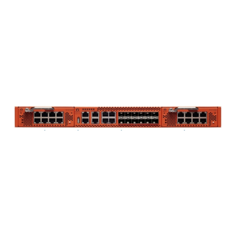
The fully-assembled GigaVUE-HC1P chassis consists of a 1RU, rack-mountable chassis with
management, network, and tool ports at the front and power connections and fans at the
rear. Figure 1 Front View of GigaVUE-HC1P Chassis summarizes the bays and components
at the front and Figure 2 Rear View of GigaVUE-HC1P Chassis summarizes the rear of the
GigaVUE-HC1P chassis.
Figure 1 Front View of GigaVUE-HC1P Chassis
Figure 2 Rear View of GigaVUE-HC1P Chassis
Introducing the GigaVUE-HC1P Chassis 8
GigaVUE-HC1-PLUS Hardware Installation Guide

NOTE:The GigaVUE-HC1P chassis arrives from the factory with power supply modules
and fans installed. The GigaVUE-HC1P modules are shipped separately. Refer to
Unpacking the GigaVUE-HC1P Shipment for assembly instructions.
Front Components on the GigaVUE-HC1P Chassis
Module Bays The base chassis is in the center and numbered 1. Slots (bays) are numbered 2-3
from left to right.
Base Chassis The GigaVUE-HC1P includes a base chassis which holds the management and
processing components installed inside the unit. It is located in the center of the
front of the chassis.
NOTE:The base chassis is not hot-swappable.
The base chassis also controls the Mgmt port and console port on the front of the
node for network and local administrative access to the GigaVUE-OS command-
line interface (CLI). The base chassis provides 4x100G/40G ,8x25G/10G/1G support.
The default port speed is 100G/10Gwhich is denoted withC/X.
Every group of four ports (quad) can be configured as 25Gb. In one quad, there
cannot be a mix of 10Gb and 25Gb ports. By default, all eight ports are configured
as 10Gb ports. To configure 25Gb, you must configure the port speed as follows:
(config) # port 1/2/x1..x4 params admin enable (config) # port 1/2/x1..x4 params
speed 25000
Refer to GigaVUE-HC1P Base Chassis for more information.
Management Ports The Ethernet port supports remote connections to the GigaVUE-OS using SSH .
Console Ports Initial tap configuration is performed in the CLI over the serial RJ-45 Console port.
Serial Console port accepts terminal connections for configuration of
GigaVUE-HC1P settings, including time, network, and SNMP settings.
USB Use the USB port to upgrade software on the GigaVUE-HC1P using a software
image on an external USB drive. Refer toDual BIOS Image
Table 1: GigaVUE-HC1P Chassis Components
Introducing the GigaVUE-HC1P Chassis 9
GigaVUE-HC1-PLUS Hardware Installation Guide

Reset /Push Button Use the reset/ push button to reset the device.
Rear Components on the GigaVUE-HC1P Chassis
Power Supply Modules The GigaVUE-HC1P includes two separate power supply modules already
installed at the rear of the node. Each power supply module can independently
operate the GigaVUE-HC1P for 1+1 system redundancy and are hot swappable.
Separate AC and DC power units are available.
Refer to Power Requirements for information on power characteristics of the
GigaVUE-HC1P.
Refer to Module Removal and Replacement Procedure (Hot Removal) for more
information on hot-swapping the module.
SMT-HC1A-R GigaSMART
Module
The fixed rear GigaSMART line card comes with 2.0GHzcapability. The ports in
this module are compatible with all features that are supported by GigaVUE H
Series platforms.
Fan Trays The fan trays installed at the rear of the node provide system cooling. Fan trays
are also hot-swappable.Refer to Module Removal and Replacement Procedure
(Hot Removal) for more information on hot-swapping the module.
Hardware Root of Trust (HRoT)
The Hardware Root of Trust is a solution that intends to seek the root of trust in the system
with the help of secure micro-controller, highly resistant to attacks and provide most robust
form of IP security with multiple level of key verification during power on.
To configure the HRoT solution refer GigaVUE-OS CLI Reference Guide.
Dual BIOS Image
The GigaVUE-HC1P has a dual Basic Input/Output System (BIOS). The BIOS image is
packaged with the software image, starting in software version 6.0. The BIOS contents are
stored in flash memory, allowing the BIOS to be upgraded. There are two flash components,
a primary and a secondary.
The following CLI command displays the two flash components and indicates the BIOS
image from which the system booted using asterisks:
(config) show version
...
1st flash version: Yantra.41.011p.0 **
2nd flash version: Yantra.41.011p.0
SW BIOS version: Yantra.41.011p.0
...
Introducing the GigaVUE-HC1P Chassis
Hardware Root of Trust (HRoT) 10
GigaVUE-HC1-PLUS Hardware Installation Guide
If there is a component failure in the primary flash, the GigaVUE-HC1P boots from a backup
golden BIOS image in the secondary flash. An SNMP trap can be configured to be sent when
the system has booted from the secondary flash. The trap may indicate that the primary
flash component needs to be serviced. The trap is as follows:
2ndflashboot: Secondary flash boot notification
If a BIOS upgrade is needed for enhancements in future releases, the BIOS can be manually
upgraded from the CLI using the coreboot install command.
Chassis Cooling
The fans on the GigaVUE-HC1P run at 100% of their maximum speed on power up, then drop
to approximately 65% during normal operations. The fans are deployed in 2+1 redundancy
mode, meaning that a single fan can fail and immediately the third fan can help the chassis
maintain the appropriate cooling temperature at 40ºC ambient.They are also hot-
swappable.Refer to Module Removal and Replacement Procedure (Hot Removal) for more
information on hot-swapping the module.
The temperatures of five components: intake, exhaust, CPU, switch CPU, and GigaSMART
CPU temperatures, are monitored. When a component crosses a pre-defined threshold, the
fan speed is adjusted dynamically, in increments of approximately 10%.
An SNMP trap is sent when a component reaches the threshold for warning, alert, or critical
temperature conditions. Refer to Table 2: Component Temperature Thresholds and Actions
for the temperatures at which the warning, alert, and critical traps are sent.
Table 2: Component Temperature Thresholds and Actions
Exhaust
Temperature
CPU
Temperature
Switch CPU
Temperature
GigaSMART CPU
Temperature
85ºC
Warning trap sent
90ºC
Warning trap sent
105ºC
Warning trap sent
90ºC
Warning trap sent
90ºC
Alert trap sent
95ºC
Alert trap sent
115ºC
Alert trap sent
95ºC
Alert trap sent
95ºC
Critical trap sent
100ºC
Critical trap sent
140ºC
Critical trap sent
100ºC
Critical trap sent
The output of the following CLI command displays the current intake, exhaust, CPU, switch
CPU temperatures, as well as the GigaSMART CPU temperature. The output of the following
CLI command displays the fan speed in RPM (the normal operational speed is approximately
12000RPM; the maximum speed is approximately 19000RPM):
HC1P-HROT-Remote (config) # show environment
*** Box 1 (GVS-HC1P0/CHS-HW) ***
-----------------------------------------------------------
Power Module 1 (PWR-TAC21):
Product Code : 132-00F1
Serial Num : 1F10-06A1
Introducing the GigaVUE-HC1P Chassis
Chassis Cooling 11
GigaVUE-HC1-PLUS Hardware Installation Guide

HW Rev : A0
Status : on
Capacity : N/A
12v voltage : 11.941 V
-----------------------------------------------------------
Power Module 2 (N/A):
Product Code : N/A
Serial Num : N/A
HW Rev : N/A
Status : absent
Capacity : N/A
12v voltage : 0.0 V
-----------------------------------------------------------
Fan tray 1 (FAN-HC1P):
1st fan : 14195 RPM
2nd fan : 13063 RPM
3rd fan : 14144 RPM
4th fan : 13063 RPM
-----------------------------------------------------------
Fan tray 2 (FAN-HC1P):
1st fan : 13845 RPM
2nd fan : 12725 RPM
3rd fan : 13845 RPM
4th fan : 12684 RPM
-----------------------------------------------------------
Fan tray 3 (FAN-HC1P):
1st fan : 13797 RPM
2nd fan : 12684 RPM
3rd fan : 13845 RPM
4th fan : 12684 RPM
-----------------------------------------------------------
Card cc1 (GVS-HC1P0/MB-HW):
Intake temperature : 29 C
Exhaust temperature : 35 C
Cpu temperature : 35 C
Switch temperature : 36 C
vddcore_td3 voltage : 0.817V
0.8v voltage : 0.798V
3.3v voltage : 3.281V
5.0v voltage : 5.000V
3.3v_fpga voltage : 3.320V
2.5v voltage : 2.520V
1.8v voltage : 1.790V
1.2v voltage : 1.190V
1.0v voltage : 0.970V
2.5v_fpga voltage : 2.490V
core_fpga voltage : 1.100V
-----------------------------------------------------------
Card 2 (PRT-HC1-Q04X08-HW):
Intake temperature : 40 C
Exhaust temperature : 32 C
-----------------------------------------------------------
Card 4 (SMT-HC1P-R):
Intake temperature : 32 C
Exhaust temperature : 37 C
oct0_vdd_3.3v voltage : 3.323V
oct0_vdd_sys_ddr0 voltage : 0.855V
Introducing the GigaVUE-HC1P Chassis
Chassis Cooling 12
GigaVUE-HC1-PLUS Hardware Installation Guide
oct0_vdd_sys_ddr1 voltage : 0.856V
oct0_vdda_gser voltage : 1.074V
oct0_vdd_ddr0 voltage : 1.199V
oct0_vdd_ddr1 voltage : 1.199V
oct0_vdd_core voltage : 0.947V
oct0_vdd_sys voltage : 0.849V
oct0_vdd_2.5v_vpp0 voltage : 2.503V
oct0_vdd_2.5v_vpp1 voltage : 2.515V
oct0_vddhv_gser voltage : 1.224V
hotswap_control voltage : 11.918V
vcc_fan_3v3 voltage : 3.318V
===========================================================
HC1P-HROT-Remote (config) # show environment type fan
*** Box 1 (GVS-HC1P0/CHS-HW) ***
-----------------------------------------------------------
Fan tray 1 (FAN-HC1P):
1st fan : 14246 RPM
2nd fan : 13020 RPM
3rd fan : 14195 RPM
4th fan : 12977 RPM
-----------------------------------------------------------
Fan tray 2 (FAN-HC1P):
1st fan : 13797 RPM
2nd fan : 12643 RPM
3rd fan : 13845 RPM
4th fan : 12643 RPM
-----------------------------------------------------------
Fan tray 3 (FAN-HC1P):
1st fan : 13797 RPM
2nd fan : 12643 RPM
3rd fan : 13845 RPM
4th fan : 12684 RPM
===========================================================
HC1P-HROT-Remote (config) #
The show chassis command gives the following:
Introducing the GigaVUE-HC1P Chassis
Chassis Cooling 13
GigaVUE-HC1-PLUS Hardware Installation Guide
Air Flow Direction
The air flow direction is from the front of the GigaVUE H Series chassis to the rear. The rear-
mounted fans pull air from the front to the back of the chassis. For environments with
hot/cold aisles, install the chassis so the intake air at the front of the chassis is cold.
AC- and DC-Powered GigaVUE-HC1P
Gigamon provides both AC- and DC-powered versions of the GigaVUE-HC1P. Refer to
Connecting Power to the GigaVUE-HC1P for information on connecting AC and DC power
supplies.
Breakout Panels
Breakout panels let you connect ports on a GigaVUE H Series node to a tool or network port
or TAP for port breakout or aggregation.
The following breakout panels are available:
■PNL-M341/PNL-M341T
■PNL-M343/PNL-M343T
Refer to G-TAP MSeries Hardware Guide for details.
Introducing the GigaVUE-HC1P Chassis
Air Flow Direction 14
GigaVUE-HC1-PLUS Hardware Installation Guide
GigaVUE-HC1P Base Chassis
The base chassis HC1P-C04X08 is the heart of the GigaVUE-HC1P, providing both processing
and switching fabric resources, as well as user access to the CLI via the Mgmt/console ports.
Port Numbering
The base chassis uses standard conventions for identifying network/ tool ports, both on the
modules themselves, as well as in the CLI:
100Gb/40Gb Ports ■Numbered with a leading C. For example, the base chassis
includes 100Gb/40Gb ports C1 to C4.
25Gb/10Gb/1Gb Ports ■Numbered with a leading X. For example, the base chassis
includes 25Gb/10Gb/1Gb ports X1 to X8.
NOTE:In one quad( a group of four ports), there cannot be a mix of
10Gb,25Gb ports or 1 Gb ports.
NOTE:When referring to ports in the CLI, the format is box ID/slot ID/port ID. For
example, 1/1/x6 refers to box 1, slot 1, port X6.
■GigaVUE-HC1P: The base chassis is numbered 1. Slots (bays) are numbered 2-3 from left
to right.
NOTE:The port labels on the base chassis faceplate use upper-case C, and
Xcharacters to identify ports. However, the CLI uses lowercase notation to refer to
ports (for example, c1 and x1).
GigaVUE-HC1P Base Chassis
Port Numbering 15
GigaVUE-HC1-PLUS Hardware Installation Guide

Module Status LEDs
The module status LEDs are as follows:
lRDY is the Ready LED. It has the following states:
oRED indicates the system is booting up
oGREEN indicates the system is ready
lPOWER is the Power LED. It has the following state:
oGREEN indicates the module is receiving power
System LED
The system LED on the front of the chassis is as follows:
■Slow blink RED indicates that HRoT MCU is in pre-boot phase.
■Fast blink RED indicates that the HRoT MCU has loaded and started to execute
primary/golden firmware image.
■Slow blink GREEN indicates that the HRoT MCU has authenticated BIOS image and
allowed the CPU to start booting up.
■Fast blink GREEN indicates that the BIOS boot-up is complete. If the system has booted
BIOS from the golden path, the SYS LED will continue to show “Fast blink GREEN” state
even after the GigaVUE-OS is up.
■Solid GREEN indicates that the system has booted completely via the primary path, the
GigaVUE_OS is UP and the system is operating normally without alarms.
■Solid RED indicates Boot-up failure after system is online and operational. It also
indicates a critical alarm (such as over-temperature).
PSU Led
The individual power LED status on the chassis are as follows:
■OFF indicates that no power is being received by the PSU.
■Blinking GREEN indicates that the system has two PSUs of which one is operating
normally without any warning/alarm and the other has no input voltage.
■Solid GREENindicates normal operation.
Management Port LED
The Management Port LED on the front of the chassis is as follows:
■The LINK LED( Left side) status are as below:
GigaVUE-HC1P Base Chassis
Module Status LEDs 16
GigaVUE-HC1-PLUS Hardware Installation Guide

oOff indicates that there is no link established on the port.
oSolid GREEN indicates that a valid link at 1000Mbps is established on the port.
■The ACT LED( right side) status are as below:
oOff indicates that there is no link is established on the port.
oBlinking GREEN indicates that the port is active and is transmitting or receiving
packet.
Fan Status LED
The Fan status LEDs on the front of the chassis are as follows:
■OFF indicates that there is no power.
■Blinking RED indicates that one fan tray is missing or failed (system can operate with
one failed or missing fan tray but needs servicing).
■Solid REDindicates that more than one fan tray is missing or has failed
■Solid GREEN indicates normal operation is happening with all fans in healthy state.
The Fan status LEDs on the front and the rear of the chassis are as follows:
■Solid GREEN indicates that the fan is operating normally.
■Solid AMBERindicates that the fan has failed.
Base Chassis Port Status LEDs
The 10Gb port status LED has the following states:
lOff indicates the port is administratively enabled, but the link is operationally down.
lGREEN indicates the link is operationally up.
GigaVUE-HC1PModules
The GigaVUE-HC1P has two bays for replaceable modules. The following modules are
available for the GigaVUE-HC1P:
Module Description Section
BPS-HC1-D25A60
and BPS-HC1-
D35C60
Bypass Modules, GigaVUE-HC1P, with Six SX/SR (50/125μm
multimode) and Six LX/LR single mode inline network port
pairs
Bypass Modules (BPS-
HC1-D25A60 SX/SR,
BPS-HC1-D35C60
LX/LR)
GigaVUE-HC1PModules
Fan Status LED 17
GigaVUE-HC1-PLUS Hardware Installation Guide

Module Description Section
SMT-HC1A-R The rear GigaSMART line card with 2.0GHzcapability. The
ports in this module are compatible with all features that
are supported by GigaVUE H Series platforms
SMT-HC1A-R Module
PRT-HC1-Q04X08
Module
The PRT-HC1-Q04X08 line card module increases the port
density and allows GigaVUE-HC1P to connect with
GigaVUE-TA Series and GigaVUE HC Series nodes with
higher-speed (100Gb/25Gb) links
PRT-HC1-Q04X08
Module
Generation 3
GigaSMART Card
(SMT-HC1-S)
Generation 3 GigaSMART module, (SMT-HC1-S), gives80Gb
throughput.
Generation 3
GigaSMART Card
Modules are hot-swappable and can be installed in any of the available front bays in a
GigaVUE-HC1P node. However, refer to Module Removal and Replacement Procedure (Hot
Removal) for instructions – you must follow a specific procedure when removing modules to
preserve node stability.
Bypass Modules (BPS-HC1-D25A60 SX/SR, BPS-
HC1-D35C60 LX/LR)
The BPS-HC1-D25A60 is multi-mode SR and BPS-HC1-D35C60 is single-mode LR 1Gb/10Gb
bypass modules. Bypass Modules offer six inline network port pairs each.
Table 3: BPS-HC1-D25A60
GigaVUE-HC1PModules
Bypass Modules (BPS-HC1-D25A60 SX/SR, BPS-HC1-D35C60 LX/LR) 18
GigaVUE-HC1-PLUS Hardware Installation Guide

Table 4: BPS-HC1-D35C60
Before installing a Bypass Module, the GigaVUE-HC1P must be running on the software
version 6.00 or higher. For internal transceiver and loss summary specifications, refer to
Bypass Module Specifications.
The GigaVUE-HC1P offers physical and logical inline bypass. Physical bypass provides
automatic failover protection in the case of a power failure. The bypass modules provide the
physical bypass function. As it applies to a single pair of inline network ports, the physical
bypass function is as follows:
lWhen the module is not powered, (either the entire node is powered down or the
module is removed from the node), the inline network port pair is in the physical
bypass mode. That means that traffic is exchanged directly between network Port A
and network Port B of the inline network pair.
lWhen the module is powered, the mode (inline or bypass) of the inline network port
pair is controlled through software. In the physical bypass mode, the inline network
port pair behaves exactly as if the module was not powered. In the inline mode, the
inline network port pair behaves as any other inline network port pair configured for
working with an inline tool.
Features of the 10Gb Bypass Modules:
■Six inline network port pairs that pass traffic bi-directionally.
■Port pairs that offer optical protection switch for physical bypass.
■A mode to select either bypass or inline.
■A module that is hot swappable. Refer to procedures in Module Removal and
Replacement Procedure (Hot Removal).
GigaVUE-HC1PModules
Bypass Modules (BPS-HC1-D25A60 SX/SR, BPS-HC1-D35C60 LX/LR) 19
GigaVUE-HC1-PLUS Hardware Installation Guide

Module Status LEDs
The following module status LEDs are located on the front of the bypass modules:
■RDY is the Ready LED. It has the following states:
oRED indicates system booting or module down
oGREEN indicates normal condition
■POWER is the Power LED. It has the following state:
oGREEN indicates the module is receiving power
Inline Network Ports
Connect inline networks to the inline network ports. The inline network ports have built-in
protection for power down.
The inline network status LEDs have the following labels:
• A—Inline network LED A
• B—Inline network LED B
• M—Mode LED (on is inline and off is bypass)
Using Bypass Modules for Gigamon Resiliency for Inline Protection
■Gigamon Resiliency for Inline Protection (GRIP)™ is an inline bypass solution that
connects two GigaVUE-HC1P nodes together so that one node provides high availability
to the other node when there is a loss of power. This redundant arrangement of two
GigaVUE-HC1P nodes maintains traffic monitoring by inline tools when one of the
nodes is down.
■GRIP™ makes use of the bypass protection switch relays for protected inline networks
on GigaVUE-HC1P nodes. The bypass modules can provide physical protection for
protected pairs of optical inline network ports required by the GRIP solution.
■To configure the GRIP solution, the GigaVUE-HC1P must be running GigaVUE-OS
version 6.0 or higher. For solution and configuration information, refer to the chapter
“Configuring Inline Bypass Solutions” in the GigaVUE-OS-CLI Reference Guide.
SMT-HC1A-R Module
SMT-HC1A- Ris the GigaSMART rear module of GigaVUE-HC1P with 2.0GHzcapability. This
GigaSMART module has one GigaSMART chip that supports 2 x 100G links. The ports in this
module are compatible with all features that are supported by GigaVUE H Series platforms.
The rear GigaSMART module is a fixed card and cannot be can be installed/removed.
GigaVUE-HC1PModules
SMT-HC1A-R Module 20
GigaVUE-HC1-PLUS Hardware Installation Guide
Other manuals for GigaVUE H Series
3
This manual suits for next models
12
Table of contents
Other Gigamon Network Hardware manuals

Gigamon
Gigamon GFM-HW1-FM010 User manual

Gigamon
Gigamon GigaVUE H Series Manual

Gigamon
Gigamon GigaVUE-TA100-CXP User manual

Gigamon
Gigamon GigaVUE TA Series Manual

Gigamon
Gigamon GigaVUE TA Series Manual

Gigamon
Gigamon GigaVUE TA Series Manual

Gigamon
Gigamon G-TAP M Series Installation instructions

Gigamon
Gigamon GigaVUE-HC3 Manual

Gigamon
Gigamon GigaVUE TA Series Manual

Gigamon
Gigamon GigaVUE-HC1-PLUS User manual