Dell EMC VxRail P series User manual

VxRail Appliances on 14th Generation
PowerEdge
P Series, V Series, and S Series Appliance Owner's
Manual
01

Copyright ©2017 Dell Inc. or its subsidiaries. All rights reserved.
Published November 2017
Dell believes the information in this publication is accurate as of its publication date. The information is subject to change without notice.
THE INFORMATION IN THIS PUBLICATION IS PROVIDED “AS-IS.“ DELL MAKES NO REPRESENTATIONS OR WARRANTIES OF ANY KIND
WITH RESPECT TO THE INFORMATION IN THIS PUBLICATION, AND SPECIFICALLY DISCLAIMS IMPLIED WARRANTIES OF
MERCHANTABILITY OR FITNESS FOR A PARTICULAR PURPOSE. USE, COPYING, AND DISTRIBUTION OF ANY DELL SOFTWARE DESCRIBED
IN THIS PUBLICATION REQUIRES AN APPLICABLE SOFTWARE LICENSE.
Dell, EMC, and other trademarks are trademarks of Dell Inc. or its subsidiaries. Other trademarks may be the property of their respective owners.
Published in the USA.
EMC Corporation
Hopkinton, Massachusetts 01748-9103
1-508-435-1000 In North America 1-866-464-7381
www.EMC.com
2VxRail Appliances on 14th Generation PowerEdge P Series, V Series, and S Series Appliance Owner's Manual

Overview 5
Supported configurations............................................................................. 7
Front view of the appliances.........................................................................8
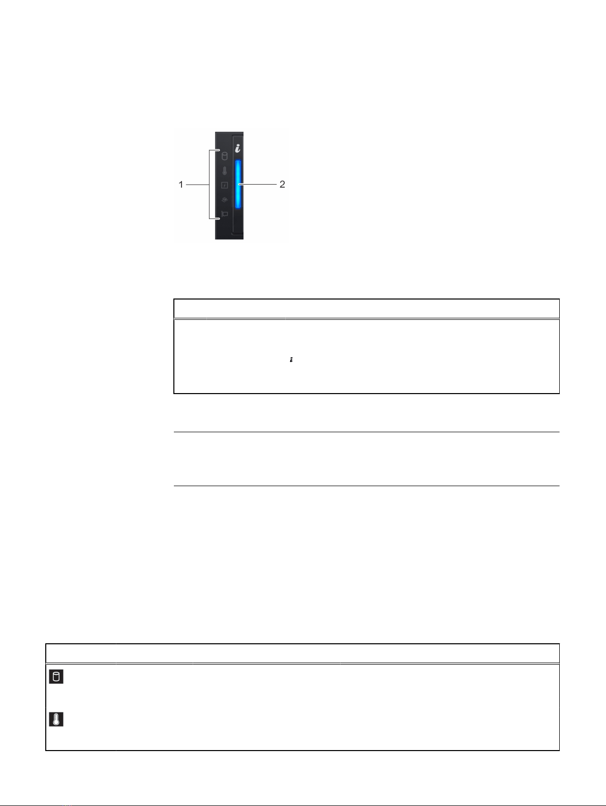
Left control panel view...................................................................10
Right control panel view.................................................................12
Back view of the appliance..........................................................................14
NIC indicator codes........................................................................15
Power supply unit indicator codes..................................................16
Hard drive indicator codes.......................................................................... 19
Locating the serial number of your appliance..............................................20
Looking up your appliance serial number in VxRail Manager.......... 20
Locating your physical VxRail Service Tag number........................ 20
Documentation matrix 23
Technical specifications 25
Chassis dimensions.....................................................................................26
Chassis weight........................................................................................... 26
Processor specifications.............................................................................27
PSU specifications......................................................................................27
Battery specifications.................................................................................28
Expansion bus specifications...................................................................... 28
Memory specifications............................................................................... 29
Storage controller specifications................................................................ 29
Drives......................................................................................................... 30
Ports and connectors specifications...........................................................30
USB ports......................................................................................30
NIC ports.......................................................................................30
VGA ports......................................................................................30
Serial connector............................................................................. 31
Internal Dual SD Module.................................................................31
Video specifications.................................................................................... 31
Environmental specifications.......................................................................31
Standard operating temperature....................................................33
Expanded operating temperature.................................................. 33
Particulate and gaseous contamination specifications................... 35
Initial setup and configuration 37
Pre-operating systems 39
Options to manage the pre-operating system applications......................... 40
iDRAC configuration...................................................................................40
Log in to iDRAC............................................................................. 40
Replacing and adding hardware 41
Using the SolVe Desktop application for VxRail Series hardware tasks.......42
System memory......................................................................................... 42
Chapter 1
Chapter 2
Chapter 3
Chapter 4
Chapter 5
Chapter 6
CONTENTS
VxRail Appliances on 14th Generation PowerEdge P Series, V Series, and S Series Appliance Owner's Manual 3

General memory module installation guidelines..............................44
Expansion cards and expansion card riser...................................................44
Expansion card installation guidelines............................................ 45
Getting help 47
Contacting EMC.........................................................................................48
Registering for online support.................................................................... 48
Accessing support resources......................................................................48
Chapter 7
CONTENTS
4VxRail Appliances on 14th Generation PowerEdge P Series, V Series, and S Series Appliance Owner's Manual

CHAPTER 1
Overview
The VxRail appliances are hyper-converged appliances that support the following
configurations:
VxRail appliances supported configurations
Table 1 VxRail appliances supported configurations
Supported
configurations
VxRail V Series VxRail P Series VxRail S Series
Processor Two Intel Xeon Processor
Scalable Family
processors
Up to two Intel Xeon
Processor Scalable Family
processors
Up to two Intel
Xeon Processor
Scalable Family
processors
DIMM 24 DIMM slots
supporting up to 1536 GB
of memory
24 DIMM slots supporting
up to 1536 GB of memory
24 DIMM slots
supporting up to
1536 GB of
memory
Power supply
units
Two AC or DC redundant
power supply units
Two AC or DC redundant
power supply units
Two AC or DC
redundant power
supply units
Drives 24 hard drives or solid
state drives (SSDs)
24 hard drives or solid
state drives (SSDs)
12 front
accessible hard
drives or solid
state drives
(SSDs), and two
rear accessible
SSDs
Note
The appliances supports only internal, hot-swappable hard drives.
Note
In this document, HDD generically refers to both HDD and SSD.
Note
All instances of SAS, SATA drives, and SSDs are referred to as drives in this
document, unless specified otherwise.
lSupported configurations.....................................................................................7
lFront view of the appliances................................................................................ 8
Overview 5

lBack view of the appliance................................................................................. 14
lHard drive indicator codes.................................................................................. 19
lLocating the serial number of your appliance..................................................... 20
Overview
6VxRail Appliances on 14th Generation PowerEdge P Series, V Series, and S Series Appliance Owner's Manual

Supported configurations
The VxRail P Series, V Series, and S Series appliances support the following
configurations:
Figure 1 Supported configuration of VxRail P Series and V Series
1. drive backplane
2. backplane expander card
3. cooling fan in the cooling fan assembly (6)
4. memory module
5. CPU2 processor and heat sink module socket (with dust cover)
6. expansion card riser 3
7. network daughter card
8. expansion card riser 2
9. system board
10. expansion card riser 1
Overview
Supported configurations 7

Figure 1 Supported configuration of VxRail P Series and V Series (continued)
11. integrated storage controller card
12. CPU1 processor and heat sink module
Figure 2 Supported configuration of VxRail S Series
1. drive backplane
2. backplane expander card
3. cooling fan in the cooling fan assembly (6)
4. memory module
5. CPU2 processor and heat sink module socket
6. rear drive cage 1
7. rear drive cage 2
8. system board
9. expansion card riser 1
10. integrated storage controller card
11. CPU1 processor and heat sink module
Front view of the appliances
The front view displays the features available on the front of the appliance. You can
access components such as the power button, left control panel, and right control
Overview
8VxRail Appliances on 14th Generation PowerEdge P Series, V Series, and S Series Appliance Owner's Manual

panel from the front of the system. The diagnostic LEDs are prominently located on
the front panel. The hot-swappable hard drives are accessible from the front panel.
Figure 3 Front view of VxRail P Series, and V Series – 24 x 2.5 inch drive appliance
Figure 4 Front view of VxRail S Series –12 x 3.5 inch drive appliance
The table below describes the features available on the front view:
Table 2 Features available on the front of the appliance
Item Panels and
slots
Icon Description
1 Left control panel N/A Contains appliance health and appliance ID,
status LED.
2 Hard drives N/A Enable you to install drives that are supported
on your appliance. For more information about
drives, see Technical specifications on page
25.
3 Right control
panel
N/A Contains the power button, VGA port, iDRAC
Direct micro-USB port and two USB 2.0 ports.
4 Information tag N/A The Information Tag is a slide-out label panel
that contains appliance information such as
Service Tag, Product Serial Number Tag
(PSNT), NIC, MAC address, and so on.
Overview
Front view of the appliances 9

Left control panel view
Figure 5 Left control panel view
The table below describes the left control panel features:
Table 3 Left control panel features
Item Indicator Icon Description
1 Status LED
indicators
N/A Indicate the status of the appliance. For more
information, see Status LED indicators.
2 Appliance health
and appliance ID
indicator
Indicates the appliance health. For more
information, see Appliance health and appliance
ID indicator codes on page 11.
Status LED indicators
Note
The status LED indicators are always off and only turns on to a solid amber if any error
occurs.
Item 1 is the health indicator, that indicates the health status of the appliance. The
indicator turns solid blue if the appliance is turned on and in good health. The indicator
flashes amber if the appliance is turned on or in standby, and if any issue occurs (for
example, a failed fan or drive). Item 2 is the drive indicator, that flashes amber if an
error occurs related to drive. Item 3 is the electrical indicator that flashes amber if an
electrical error occurs (for example, voltage out of range, or a failed power supply unit
or voltage regulator). Item 4 is the temperature indicator that flashes amber if a
thermal error occurs (for example, a temperature out of range or fan failure). Item 5 is
the memory indicator that flashes amber if a memory error occurs. Item 6 is the PCIe
indicator that flashes amber if an error occurs related to PCIe card.
Table 4 Status LED indicators and descriptions
Icon Description Condition Corrective action
Hard drive
indicator
The indicator turns solid amber if
there is a hard drive error.
Check the System Event Log to determine if the
drive has an error. If the problem persists, see
Getting help on page 47.
Temperature
indicator
The indicator turns solid amber if
the appliance experiences a
thermal error (for example, the
Ensure that none of the following conditions exist:
lA cooling fan has been removed or has failed.
Overview
10 VxRail Appliances on 14th Generation PowerEdge P Series, V Series, and S Series Appliance Owner's Manual

Table 4 Status LED indicators and descriptions (continued)
Icon Description Condition Corrective action
ambient temperature is out of
range or there is a fan failure).
lAppliance cover, air shroud, memory module
blank, or back filler bracket is removed.
lAmbient temperature is too high.
lExternal airflow is obstructed.
If the problem persists, see Getting help on page
47.
Electrical
indicator
The indicator turns solid amber if
the appliance experiences an
electrical error (for example,
voltage out of range, or a failed
power supply unit (PSU) or
voltage regulator).
Check the System Event Log or appliance messages
for the specific issue. If it is due to a problem with
the PSU, check the LED on the PSU. Reseat the
PSU. If the problem persists, see Getting help on
page 47.
Memory
indicator
The indicator turns solid amber if a
memory error occurs.
See the Getting help on page 47 section.
PCIe indicator The indicator turns solid amber if a
PCIe card experiences an error.
See the Getting help on page 47 section.
Note
For more information about the supported PCIe
cards, see Expansion card installation guidelines on
page 45.
Appliance health and appliance ID indicator codes
The appliance health and appliance ID indicator is located on the left control panel of
your appliance.
Figure 6 Appliance health and appliance ID indicators
This table describes the appliance health and appliance ID indicators. Item 1 indicates
Solid blue where the condition indicates that the appliance is turned on, system is
healthy, and appliance ID mode is not active. Press the appliance health and appliance
ID button to switch to appliance ID mode. Item 2 indicates Blinking blue where the
condition indicates that the appliance ID mode is active. Press the appliance health
and appliance ID button to switch to appliance health mode. Item 3 indicates solid
amber where the condition indicates that the appliance is in fail-safe mode. If the
problem persists, see the Getting help section. Item 4 indicates blinking amber where
the condition indicates that the appliance is experiencing a fault. Check the System
Event Log or the LCD panel, if available on the bezel, for specific error message. For
more information about error messages, see the
Dell Event and Error Messages
Reference Guide
at Dell.com/openmanagemanuals > OpenManage software.
Overview
Left control panel view 11

Table 5 Appliance health and appliance ID indicator codes
Appliance health and appliance ID
indicator code
Condition
Solid blue Indicates that the appliance is turned on,
appliance is healthy, and appliance ID mode is
not active. Press the appliance health and
appliance ID button to switch to appliance ID
mode.
Blinking blue Indicates that the appliance ID mode is active.
Press the appliance health and appliance ID
button to switch to appliance health mode.
Solid amber Indicates that the appliance is in fail-safe mode.
If the problem persists, see Getting help on
page 47.
Blinking amber Indicates that the appliance is experiencing a
fault. If the problem persists, see Getting help
on page 47.
Right control panel view
Figure 7 Right control panel view
The table below describes the right control panel features
Table 6 Right control panel features
Item Indicator,
button, or
connector
Icon Description
1 Power button Indicates if the appliance is turned on or off.
Press the power button to manually turn on or
off the appliance.
Note
Press the power button to gracefully shut down
an ACPI-compliant operating system.
Overview
12 VxRail Appliances on 14th Generation PowerEdge P Series, V Series, and S Series Appliance Owner's Manual

Table 6 Right control panel features (continued)
Item Indicator,
button, or
connector
Icon Description
2 USB port (2) The USB ports are 4-pin, 2.0-compliant. These
ports enable you to connect USB devices to the
appliance.
3 iDRAC Direct
port
The iDRAC Direct port is micro USB 2.0-
compliant. This port enables you to access the
iDRAC Direct features. For more information,
see the iDRAC User’s Guide at Dell.com/
idracmanuals.
4 iDRAC Direct
LED
N/A The iDRAC Direct LED indicator lights up to
indicate that the iDRAC Direct port is
connected. For more information, see iDRAC
Direct LED indicator codes on page 13.
5 VGA port Enables you to connect a display device to the
appliance. For more information, see Technical
specifications on page 25.
iDRAC Direct LED indicator codes
The iDRAC Direct LED indicator lights up to indicate that the port is connected and is
being used as a part of the iDRAC subsystem.
iDRAC Direct LED indicator is located below the iDRAC Direct port on the right control
panel.
You can configure iDRAC Direct by using a USB to micro USB (type AB) cable, which
you can connect to your laptop or tablet. The following table describes iDRAC Direct
activity when the iDRAC Direct port is active:
The iDRAC Direct LED indicator codes table describes the iDRAC status when it is
solid green, flashing green, and when it is turned off.
Table 7 iDRAC Direct LED indicator codes
iDRAC Direct
LED indicator
code
Condition
Solid green for
two seconds
Indicates that the laptop or tablet is connected.
Flashing green (on
for two seconds
and off for two
seconds)
Indicates that the laptop or tablet connected is recognized.
Turns off Indicates that the laptop or tablet is unplugged.
Overview
Right control panel view 13

Back view of the appliance
The back view displays the features available on the back of the appliance.
Figure 8 Back view of VxRail S Series 2 – x 3.5 inch drive appliance
This table shows the features available on the back view.
Table 8 Features available on the back view
Item Panels, ports
and slots
Icon Description
1 Full-height PCIe
expansion card slot
(3)
N/A The PCIe expansion card slot (riser 1) connects
up to three full-height PCIe expansion cards to
the appliance. For more information, see
Expansion card installation guidelines on page
45.
2 Half-height PCIe
expansion card slot
N/A The PCIe expansion card slot (riser 2) connects
one half-height PCIe expansion cards to the
appliance. For more information, see Expansion
card installation guidelines on page 45.
3 Rear handle N/A The rear handle can be removed to enable any
external cabling of PCIe cards that are installed in
the PCIe expansion card slot 6.
4 Drives N/A Enable you to install drives that are supported on
your appliance. For more information about
drives, see Technical specifications on page 25.
5 Power supply unit
(2)
N/A For more information, see Technical
specifications on page 25.
6 NIC ports The NIC ports that are integrated on the network
daughter card (NDC) provide network
connectivity. For more information about the
supported configurations, see Technical
specifications on page 25.
7 USB port (2) The USB ports are 9-pin and 3.0-compliant.
These ports enable you to connect USB devices
to the appliance.
Overview
14 VxRail Appliances on 14th Generation PowerEdge P Series, V Series, and S Series Appliance Owner's Manual

Table 8 Features available on the back view (continued)
Item Panels, ports
and slots
Icon Description
8 VGA port Enables you to connect a display device to the
appliance. For more information, see Technical
specifications on page 25.
9 Serial port Enables you to connect a serial device to the
appliance. For more information, see Technical
specifications on page 25.
10 iDRAC9 dedicated
port
Enables you to remotely access iDRAC. For more
information, see the iDRAC User’s Guide at
Dell.com/idracmanuals.
11 Appliance
identification
button
The Appliance Identification (ID) button is
available on the front and back of the appliances.
Press the button to identify an appliance in a rack
by turning on the appliance ID button. You can
also use the appliance ID button to reset iDRAC
and to access BIOS using the step through mode.
NIC indicator codes
Each NIC on the back panel has indicators that provide information about the activity
and link status. The activity LED indicator indicates if data is flowing through the NIC,
and the link LED indicator indicates the speed of the connected network.
Figure 9 NIC indicator codes
1. link LED indicator
2. activity LED indicator
The NIC indicators table describes different NIC indicator codes and condition of the
connectivity.
Table 9 NIC indicator codes
Status Condition
Link and activity indicators are off The NIC is not connected to the network.
Link indicator is green and activity
indicator is blinking green
The NIC is connected to a valid network at its
maximum port speed and data is being sent or
received.
Overview
NIC indicator codes 15

Table 9 NIC indicator codes (continued)
Status Condition
Link indicator is amber and activity
indicator is blinking green
The NIC is connected to a valid network at less than
its maximum port speed and data is being sent or
received.
Link indicator is green and activity
indicator is off
The NIC is connected to a valid network at its
maximum port speed and data is not being sent or
received.
Link indicator is amber and activity
indicator is off
The NIC is connected to a valid network at less than
its maximum port speed and data is not being sent
or received.
Link indicator is blinking green and
activity is off
NIC identify is enabled through the NIC
configuration utility.
Power supply unit indicator codes
AC power supply units (PSUs) have an illuminated translucent handle that serves as
an indicator and DC PSUs have an LED that serves as an indicator. The indicator
shows whether power is present or a power fault has occurred.
Figure 10 AC PSU status indicator
1. AC PSU status indicator/handle
This table describes the AC PSU status indicators and what condition is the PSU when
the power indicator light is green, blinking green, blinking amber, and when it is not lit.
Table 10 AC PSU status indicator codes
Power indicator
codes
Condition
Green A valid power source is connected to the PSU and the PSU is operational.
Blinking amber Indicates a problem with the PSU.
Not illuminated Power is not connected to the PSU.
Blinking green When the firmware of the PSU is being updated, the PSU handle blinks
green.
Overview
16 VxRail Appliances on 14th Generation PowerEdge P Series, V Series, and S Series Appliance Owner's Manual

Table 10 AC PSU status indicator codes (continued)
Power indicator
codes
Condition
CAUTION
Do not disconnect the power cord or unplug the PSU when updating
firmware. If firmware update is interrupted, the PSUs do not
function.
Blinking green and
turns off
When hot-plugging a PSU, the PSU handle blinks green five times at a
rate of 4 Hz and turns off. This indicates a PSU mismatch with respect to
efficiency, feature set, health status, or supported voltage.
CAUTION
If two PSUs are installed, both the PSUs must have the same type of
label; for example, Extended Power Performance (EPP) label. Mixing
PSUs from previous generations servers is not supported, even if the
PSUs have the same power rating. This results in a PSU mismatch
condition or failure to turn the appliance on.
CAUTION
When correcting a PSU mismatch, replace only the PSU with the
blinking indicator. Swapping the PSU to make a matched pair can
result in an error condition and unexpected appliance shutdown. To
change from a high output configuration to a low output
configuration or vice versa, you must turn off the appliance.
CAUTION
AC PSUs support both 240 V and 120 V input voltages with the
exception of Titanium PSUs, which support only 240 V. When two
identical PSUs receive different input voltages, they can output
different wattages, and trigger a mismatch.
CAUTION
If two PSUs are used, they must be of the same type and have the
same maximum output power.
CAUTION
Combining AC and DC PSUs is not supported and triggers a
mismatch.
Overview
Power supply unit indicator codes 17

Figure 11 DC PSU status indicator
1. DC PSU status indicator
This table describes the DC PSU status indicators and what condition is the PSU when
the power indicator light is green, blinking green, blinking amber, and when it is not lit.
Table 11 DC PSU status indicator codes
Power indicator
codes
Condition
Green A valid power source is connected to the PSU and the PSU is
operational.
Blinking amber Indicates a problem with the PSU.
Not illuminated Power is not connected to the PSU.
Blinking green When hot-plugging a PSU, the PSU indicator blinks green. This
indicates that there is a PSU mismatch with respect to efficiency,
feature set, health status, or supported voltage.
CAUTION
If two PSUs are installed, both the PSUs must have the same type
of label; for example, Extended Power Performance (EPP) label.
Mixing PSUs from previous generations servers is not supported,
even if the PSUs have the same power rating. This results in a PSU
mismatch condition or failure to turn the appliance on.
CAUTION
When correcting a PSU mismatch, replace only the PSU with the
blinking indicator. Swapping the PSU to make a matched pair can
result in an error condition and unexpected appliance shutdown.
To change from a High Output configuration to a Low Output
configuration or vice versa, you must turn off the appliance.
Overview
18 VxRail Appliances on 14th Generation PowerEdge P Series, V Series, and S Series Appliance Owner's Manual

Table 11 DC PSU status indicator codes (continued)
Power indicator
codes
Condition
CAUTION
If two PSUs are used, they must be of the same type and have the
same maximum output power.
CAUTION
Combining AC and DC PSUs is not supported and triggers a
mismatch.
Hard drive indicator codes
Each hard drive carrier has an activity indicator and a status indicator. The indicators
provide information about the current status of the hard drive. The activity LED
indicates whether the hard drive is currently in use or not. The status LED indicates
the power condition of the hard drive.
Figure 12 Hard drive indicators on the hard drive and the hard drive tray backplane
1. Hard drive activity indicator
2. Hard drive status indicator
3. Hard drive backplane on hard drive tray
4. Hard drive
The hard drive indicator codes table describes the indicator codes: flashing green
twice per second, Off, flashes green, amber, and then turns off, flashes amber four
times per second, flashes green slowly, solid green, flashes green for three seconds,
amber for three seconds, and then turns off after six seconds.
Overview
Hard drive indicator codes 19

Table 12 Hard drive indicator codes
Hard drive status indicator code Condition
Flashes green twice per second Identifying drive or preparing for removal.
Off Hard drive ready for removal.
Note
The hard drive status indicator remains off until
all drives are initialized after the appliance is
turned on. Hard drives are not ready for removal
during this time.
Flashes green, amber, and then turns off Predicted drive failure.
Flashes amber four times per second Hard drive failed.
Solid green Hard drive online.
Locating the serial number of your appliance
To get support for your appliance, use the VxRail Appliance serial number, also called
the Product Serial Number Tag (PSNT). The PSNT is a 14-digit number used to
identify your appliance to EMC support.
Note
Only use the VxRail Appliance serial number to contact Customer Support.
Sometimes, you may need to supply the 7-digit Service Tag number.
There are two identification tags on your appliance:
lThe VxRail appliance serial number—You can find the serial number in VxRail
Manager, or printed on the information tag.
lThe Service Tag — You can find the Service Tag printed on the physical appliance.
Looking up your appliance serial number in VxRail Manager
1. In VxRail Manager, on the left navigation bar, click HEALTH.
2. To display appliance information, click Physical.
3. Observe the VxRail Appliance serial number, listed under the appliance ID as the
PSNT.
Locating your physical VxRail Service Tag number
Overview
20 VxRail Appliances on 14th Generation PowerEdge P Series, V Series, and S Series Appliance Owner's Manual
Other manuals for VxRail P series
2
This manual suits for next models
2
Table of contents
Other Dell EMC Network Hardware manuals

Dell EMC
Dell EMC ECS EX Series Installation instructions

Dell EMC
Dell EMC Storage NX3230 User manual

Dell EMC
Dell EMC PowerFlex Appliance User manual

Dell EMC
Dell EMC XC6420 Series User manual

Dell EMC
Dell EMC PowerEdge MX5016s Manual

Dell EMC
Dell EMC VxRail P series Quick reference guide

Dell EMC
Dell EMC SD-WAN Edge 600 Series User manual

Dell EMC
Dell EMC SD-WAN Edge 600 Series User manual

Dell EMC
Dell EMC VEP4600 User manual

Dell EMC
Dell EMC Virtual Edge Platform 1405 Series User guide