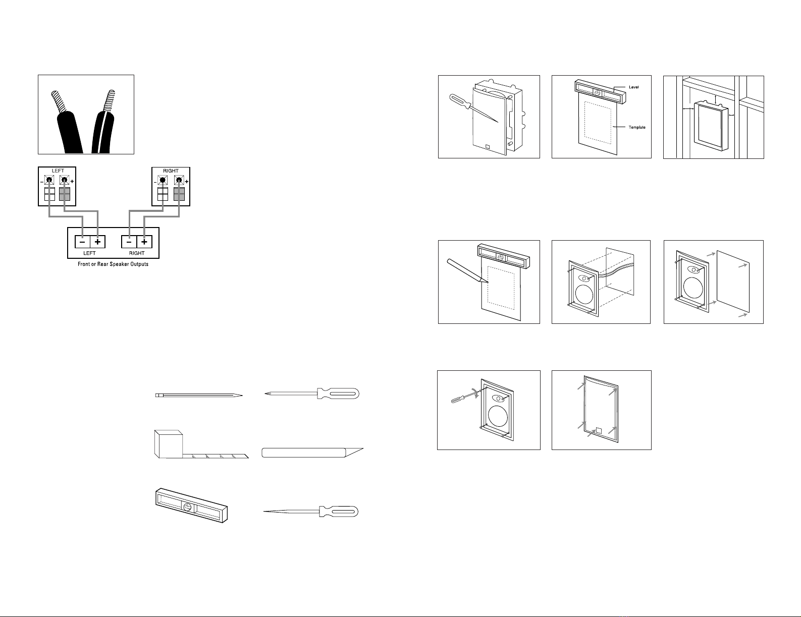
JBL 6 User manual

2
Declaration of Conformity
We, Harman Consumer International
2, route de Tours
72500 Chateau-du-Loir
France
declare in own responsibility, that the products described in this
owner’s manual are in compliance with technical standards:
EN 50081-1:1992
EN 50082-1:1997
Luc E. Godard
Harman Consumer International
Chateau-du-Loir, France 5/02
SP5 SP6 SP6C SP8 SP8C
Frequency Response Frequency Response Frequency Response Frequency Response Frequency Response
45 – 20kHz (–10dB) 38 – 20kHz (–10dB) 40 – 20kHz (–10dB) 30 – 20kHz (–10dB) 32 – 20kHz (–10dB)
Recommended Maximum Recommended Maximum Recommended Maximum Recommended Maximum Recommended Maximum
Amplifier Power
†
Amplifier Power
†
Amplifier Power
†
Amplifier Power
†
Amplifier Power
†
60 watts 80 watts 80 watts 100 watts 100 watts
Impedance Impedance Impedance Impedance Impedance
8 ohms nominal 8 ohms nominal 8 ohms nominal 8 ohms nominal 8 ohms nominal
Sensitivity Sensitivity Sensitivity Sensitivity Sensitivity
87dB (2.83V/1m) 88dB (2.83V/1m) 88dB (2.83V/1m) 89dB (2.83V/1m) 89dB (2.83V/1m)
Crossover Frequency Crossover Frequency Crossover Frequency Crossover Frequency Crossover Frequency
3,000Hz 2,000Hz 3,000Hz 2,000Hz 3,000Hz
Woofer Woofer Woofer Woofer Woofer
5-1/4" titanium-laminate cone 6-1/2" titanium-laminate cone 6-1/2" titanium-laminate cone 8" titanium-laminate cone 8" titanium-laminate cone
w/rubber surround w/rubber surround w/rubber surround w/rubber surround w/rubber surround
Tweeter Tweeter Tweeter Tweeter Tweeter
1"titanium-laminate dome, 1"titanium-laminate dome, 1"titanium-laminate dome, 1"titanium-laminate dome, 1" titanium-laminate dome,
w/Elliptical Oblate Spheroidal™w/Elliptical Oblate Spheroidal™w/Elliptical Oblate Spheroidal™w/Elliptical Oblate Spheroidal™w/Elliptical Oblate Spheroidal™
waveguide and swivel mount waveguide and swivel mount waveguide and swivel mount waveguide and swivel mount waveguide and swivel mount
Plate Size (W x H) Plate Size (W x H) Plate Size (Diameter) Plate Size (W x H) Plate Size (Diameter)
7-1/2" x 10" (191mm x 254mm) 8-1/2" x 11" (216mm x 279mm) 9-3/16" (233mm) 10-1/8" x 13-1/8" (257mm x 333mm) 10-7/8" (275mm)
Mounting Cutout Size (W x H) Mounting Cutout Size (W x H) Mounting Cutout Size (Dia.) Mounting Cutout Size (W x H) Mounting Cutout Size (Dia.)
6-1/8" x 8-11/16" (156mm x 221mm) 7-1/8" x 9-11/16" (181mm x 246mm) 7-7/8" (200mm) 8-7/8" x 11-13/16" (225mm x 300mm) 9-1/2" (240mm)
Mounting Depth Mounting Depth Mounting Depth Mounting Depth Mounting Depth
3-3/4" (95mm) 3-7/8" (98mm) 4-1/4" (108mm) 4" (102mm) 4-1/4" (108mm)
SPECIFICATIONS
All features and specifications are subject to
change without notice.
†The maximum recommended amplifier power
rating will ensure proper system headroom to
allow for occasional peaks. We do not recom-
mend sustained operation at these maximum
power levels.
*Trademark of Dolby Laboratories.
DTS is a registered trademark of
Digital Theater Systems, Inc.
DESIGN GOAL: Combine the superior performance of traditional
JBL loudspeakers with the convenience of in-wall installation.
TWEETER TYPE:
Titanium-laminate-dome with EOS
™
waveguide, and swivel mount
WOOFER TYPE:
Titanium-laminate cone with rubber surround
CROSSOVER NETWORK: Straight-Line Signal Path
™
(SSP)
PROFESSIONAL REFERENCE:Studio Monitor
OWNER’S GUIDE
PRODUCT LINE:
MODELS:
SP5, SP6, SP6C, SP8, SP8C
SOUNDPOINT
™
SERIES
©2002 JBL, Incorporated
JBL is a registered trademark of JBL, Incorporated.
Part No.
ai5235
PRO SOUND
COMES HOME™
JBL Consumer Products
250 Crossways Park Drive, Woodbury, NY 11797
8500 Balboa Boulevard, Northridge, CA 91329
800-336-4JBL (4525) (USA only)
www.jbl.com
NOTE: For new-construction applications, be sure
to purchase the correct rough-in frame kit.
SP5, SP6, SP6C,
SP8, SP8C
SOUNDPOINT™SERIES
OWNER’S GUIDE
Soundpoint OM SP5-6-6C-8-8 5/20/02 2:06 PM Page 2

3
2
INCLUDED
Template/paint shield.
Remove paint shield (inner
rectangle) at perforation.
One pair of speakers with grille.
Template/paint shield.
Remove paint shield (inner
circle) at perforation.
One pair of speakers with grille.
THANK YOU FOR CHOOSING JBL
400– 600
WALL
WALL WALL
5 – 6 ft.
WALL WALL
FRONT SPEAKERS
MODELS SP5, SP6, SP8 AS REAR SPEAKERS
MODELS SP6C, SP8C IN CEILING
SPEAKER PLACEMENT
SP5, SP6, SP8
SP6C, SP8C
For more than 50 years, JBL
has been involved in every
aspect of music and film
recording and reproduction,
from live performances to
monitoring the recordings
you play in your home,
car or office.
We’re confident that the
JBL loudspeakers you have
chosen will provide every
note of enjoyment that you
expected – and that when
you think about purchasing
additional audio equipment for
your home, car or office, you
will once again choose JBL.
Please take a moment to
complete the enclosed profile
card. It enables us to keep
you posted on our latest
advancements, and helps us
to better understand our
customers and build products
that meet their needs and
expectations.
JBL Consumer Products
Proper placement of the
speakers is an important
step in obtaining the most
realistic soundstage possible.
These recommendations are
for the optimum placement of
the loudspeakers. Use these
placement recommendations
as a guide. Slight variations
will not diminish your
listening pleasure.
The front speakers should be
placed the same distance
from each other as they are
from the listening position.
They should be placed at
about the same height from
the floor as the listener’s
ears will be.
In a home theater configura-
tion, the two surround speak-
ers should be placed slightly
behind the listening position
and, ideally, should face each
other and be at a level higher
than the listener’s ears. If that
is not possible, they may be
placed in a wall behind the
listening position, facing for-
ward. The surround speakers
should not call attention to
themselves. They should
provide a diffuse, ambient
sound accompanying the
main program material
heard in the front speakers.
Soundpoint OM SP5-6-6C-8-8 5/20/02 2:06 PM Page 2

5
4
Phillips #2 screwdriver
Measuring tape Utility knife
Pencil
Carpenter’s level Awl
TOOLS NEEDED
SP5, SP6, SP8
The SoundPoint™Series in-wall
speakers were
designed to be
easily installed. However, if you
are unsure of your ability to prop-
erly install these loudspeakers,
please contact your dealer or a
qualified installer.
INSTALLATION
EXISTING CONSTRUCTION
Remove the grille from the
speaker frame. Determine the correct speaker
location.
Note: Remove the inner template,
which is the paint shield, at the
perforation. Use the outer tem-
plate when cutting the drywall.
Note: Always allow at least
one-half inch between a wall
stud and the speaker cutout or
the locking tabs will not be able
to swivel into place.
≥1/2"
≥1/2"
≥1/2"
Cut the drywall. Connect the speaker wires
to the speaker.
Speakers and electronics
terminals have corresponding
(+) and (–) terminals. Most
manufacturers of speakers and
electronics, including JBL, use
red to denote the (+) terminal
and black for the (–) terminal.
It is important to connect both
speakers identically: (+) on the
speaker to (+) on the amplifier
and (–) on the speaker to (–)
on the amplifier. Wiring “out
of phase” results in thin sound,
weak bass and a poor stereo
image. With the advent of multi-
channel surround-sound
systems, connecting all of the
speakers in your system with
the correct polarity remains
equally important in order to
preserve the proper ambience
and directionality of the
program material.
CONNECTION TIPS
WIRE LENGTH RECOMMENDED SIZE
Up to 20 ft. 16 gauge
Up to 30 ft. 12 gauge
Greater than 30 ft. 10 gauge
The wires for both speakers
should be the same length. If
one speaker is placed closer to
the amplifier than the other,
hide the excess wire behind
the wall.
SPEAKER CONNECTIONS
Replace the metal grille.
Place the frame assembly
in the wall.
Screw down each of the four
Phillips head screws. The
locking tabs will swivel into
place and secure the unit to
the rear surface of the drywall.
Soundpoint OM SP5-6-6C-8-8 5/20/02 2:06 PM Page 4

6
SP6C, SP8C
EXISTING CONSTRUCTION NEW CONSTRUCTION
PAINTING THE SPEAKER
FRAME AND GRILLE
Remove the grille from
the speaker frame.
≥1/2"
≥1/2"
≥1/2"
Cut the drywall.
Note: Always allow at least
one-half inch between a wall
stud and the speaker cutout or
the locking tabs will not be able
to swivel into place.
Connect the speaker wires
to the speaker. Place the frame assembly
in the wall. Screw down each of the four
Phillips head screws. The
locking tabs will swivel into
place and secure the unit to
the rear surface of the drywall.
Replace the metal grille.
Determine the correct speaker
location.
Note: Remove the inner template,
which is the paint shield, at the
perforation. Use the outer tem-
plate when cutting the drywall.
SoundPoint
™
Series loud-
speakers can be painted to
match any decor. If you wish
to change their color, the satin
finish on the grille and frame
will function as a primer coat.
Before painting, install the
paint shield (inner section of
template in the assembly kit)
securely into the recess in the
baffle. This will protect the
speaker components and baf-
fle from paint residue. Use a
high-quality spray paint, and
apply a thin coat of color.
Be certain the grille perfora-
tions remain free of paint.
Filling them with paint will
diminish the sound quality.
Note: Gently remove the
acoustical foam blanket from
the grille before painting.
Reattach the blanket after the
paint has dried.
You will need to purchase the correct rough-in frame kit for your model:
SPEAKER MODEL ROUGH-IN FRAME KIT
SP5 RIF5
SP6 RIF6
SP6C RIF6C
SP8 RIF8
SP8C RIF8C
Detailed installation instructions are supplied with the rough-in kit.
TROUBLESHOOTING
IF THERE IS NO
SOUND FROM ANY
OF THE SPEAKERS:
• Check that receiver/amplifier
is on and a source is playing.
• Check all wires and connec-
tions between receiver/ampli-
fier and speakers. Make sure
all wires are connected. Make
sure none of the speaker wires
are frayed, cut or punctured.
• Review proper operation of
your receiver/amplifier.
IF THERE IS NO SOUND
COMING FROM ONE
SPEAKER:
• Check the “Balance” control
on your receiver/amplifier.
• Check all wires and connec-
tions between receiver/ampli-
fier and speakers. Make sure
all wires are connected. Make
sure none of the speaker wires
are frayed, cut or punctured.
IF THERE IS LOW (OR
NO) BASS OUTPUT:
• Make sure the connections
to the left and right “Speaker
Inputs” have the correct polar-
ity (+ and –).
• Consider adding a powered
subwoofer to your system.
• In Dolby* Digital or DTS®
modes, make sure your
receiver/processor is correctly
configured. When using a sub-
woofer, make sure the sub-
woofer output of the
receiver/processor has been
enabled. If no subwoofer is
being used, make sure the left
and right front and rear speakers
have been configured as
“LARGE.” See your
receiver/processor’s owner’s
manual for futher information
on correct speaker configura-
tion in Dolby Digital, DTS and
other surround-sound modes.
IF THE SYSTEM PLAYS
AT LOW VOLUMES
BUT SHUTS OFF AS
VOLUME IS INCREASED:
• Check all wires and connec-
tions between receiver/ampli-
fier and speakers. Make sure
all wires are connected. Make
sure none of the speaker wires
are frayed, cut or punctured.
• If more than one pair of main
speakers is being used, check
the minimum-impedance
requirements of your
receiver/amplifier.
7
Soundpoint OM SP5-6-6C-8-8 5/20/02 2:06 PM Page 6
This manual suits for next models
7
Table of contents
Other JBL Speakers manuals