JBL Control 29AV-1 User manual

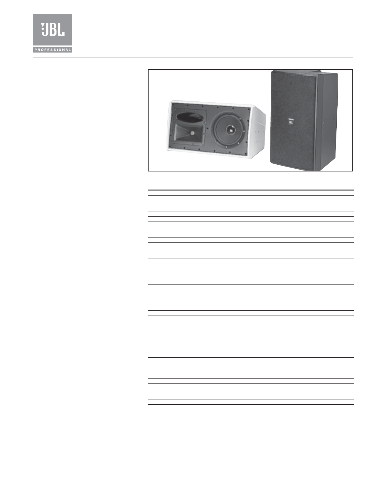
Control 29AV-1Premium Indoor/Outdoor
Monitor Speaker
®
Key Features:
䉴Extremely smooth, flat frequency
response with extended bandwidth.
䉴110° x 85° HF coverage, rotatable horn.
䉴110 Watt transformer for 70V or 100V
lines, with 8Ωthru.
䉴SonicGuard
™
overload protection.
䉴200 mm (8⬙) Kevlar cone woofer,
25 mm (1⬙) titanium diaphragm
compression driver.
䉴Includes InvisiBall
™
mounting hardware,
plus ten 6 mm attachment points for
suspension and optional U-bracket.
䉴Sealed input panel cover and screw-
down input terminals.
The Control
®
29AV-1 provides improved
voicing for extremely flat, high fidelity
performance, extended bandwidth and
well-controlled defined coverage from a
compact loudspeaker.
The rotatable high-frequency horn
allows use of the speaker in either vertical
or horizontal orientation. Consistent
coverage ensures excellent sound
character throughout the listening area.
Moderate magnetic shielding allows use
of the speaker as close as 230 mm (9⬙) to
video monitors.
The top-quality line distribution
transformer, designed for minimal insertion
loss and reduced saturation, allows
use of either 70V or 100V distributed
speaker lines. In bypass position, the 8Ω
impedance allows use of multiple speakers
on a loudspeaker line.
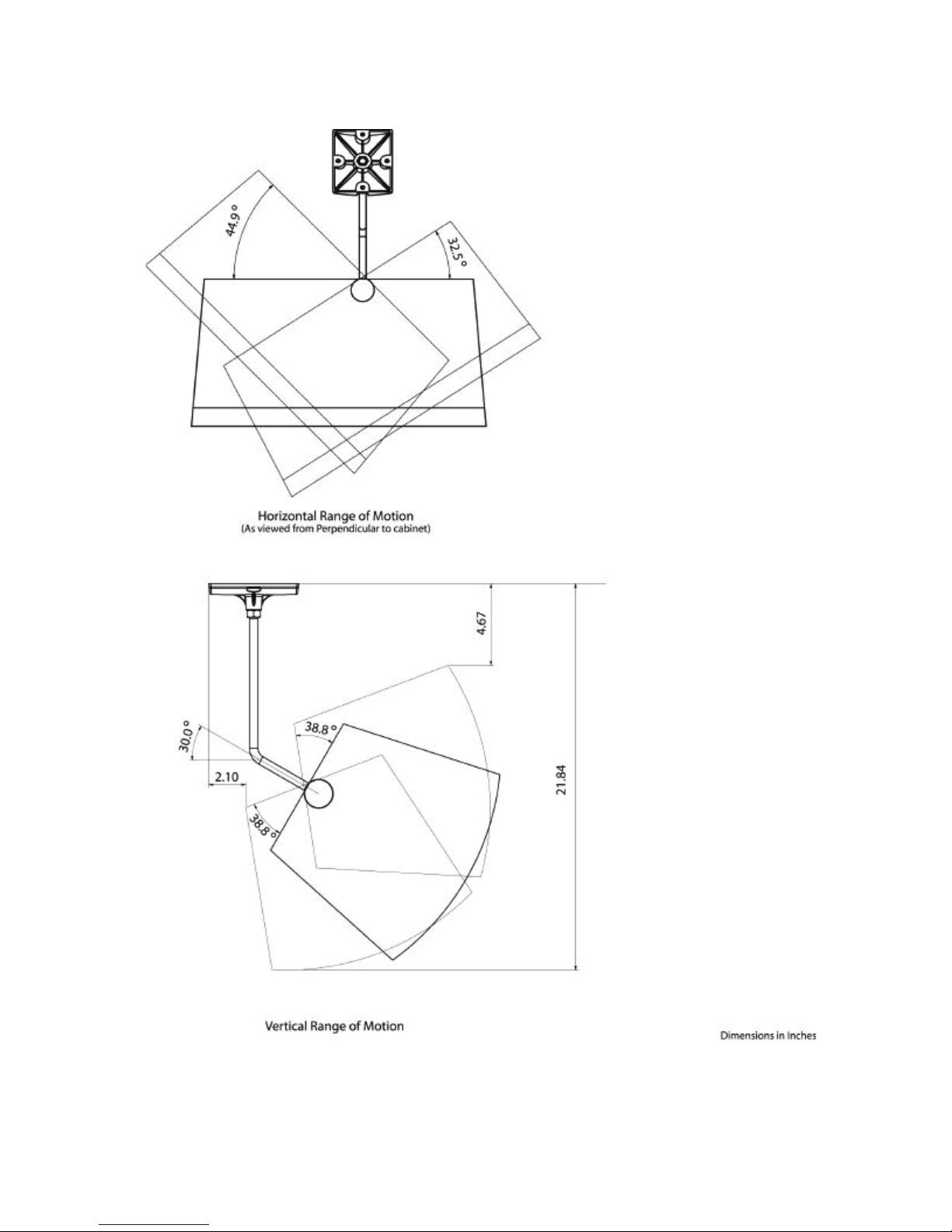
The included InvisiBall mounting
method is simple to install, aims easily and
provides a high degree of theft deterrence.
InvisiBall allows horizontal rotation of up
to 41° off-axis and vertical rotation of up
to 36° (horn end inward) or 23° (woofer
end inward). Attachment points for the
optional MTC-29UB U-bracket allows for
compact installation.
Weather resistance has been maximized.
The woofer’s cone is made of kevlar,
surround is pure butyl rubber, and the
driver basket is rear loaded to minimize
direct exposure. The compression driver’s
diaphragm is pure titanium. The grille is
thermoset composite coated and comes
with foam to minimize incursion of water.
Nickel/zinc rust-resistant terminals ensure
a secure input connection. An MTC-PC2
sealed-entrance cover is included to
further protect the speaker’s terminals.
JBL’s exclusive SonicGuard overload
protection is virtually inaudible to the
listener, ensuring reliability while
providing full fidelity sound.
Available in black or white (-WH). The
cabinet will accept a variety of paints to
match any décor.
Professional Series
Specifications:
Frequency Range (-10 dB)1: 37 Hz –18 kHz
Frequency Response (± 3 dB)1: 43 Hz – 15 kHz
100 Hr Power Capacity 2: 300 Watts Continuous Program Power
150 Watts Continuous Pink Noise
Maximum SPL @ 1m3: Short-Term: 118 dB; Long-Term: 112 dB
Nominal Sensitivity4: 90 dB, 1W @ 1 m (3.3 ft)
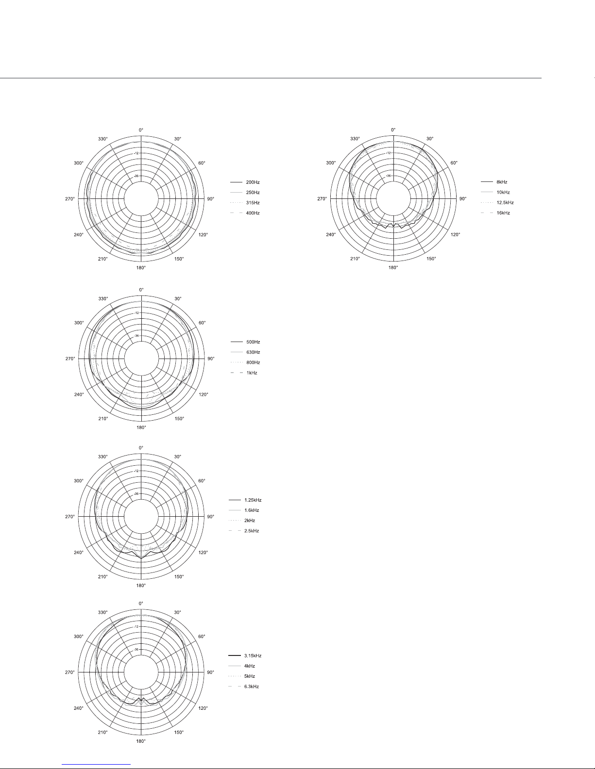
Nominal Coverage Angle5: 110° H x 85° V, rotatable
Directivity Factor (Q): 6.7, averaged 500 Hz to 16 kHz
Directivity Index (DI): 8.3 dB, averaged 500 Hz to 16 kHz
Nominal Impedance: 8 ohms
Minimum Impedance: 6.3 ohms @ 230 Hz 3.3 ohms @ 4.1 kHz
Crossover Type: 3rd order High Pass, 2nd order Low Pass with
impedance compensation, 2.5 kHz crossover
frequency
Transformer Taps: 70V: 110W, 55W, 28W & 14W
100V: 110W, 55W, & 28W
Thru Position: 8Ωnominal
Recommended High-Pass: See chart
Transducers:
Low Frequency: 200 mm (8 in) kevlar cone with pure butyl rubber
surround, 50 mm (2 in) voicecoil on fiberglass
former
High Frequency: 25 mm (1 in) compression driver, pure titanium
diaphragm with patented JBL diamond surround
Physical:
Enclosure Material: High impact polystyrene
Grille: Thermoset composite coated steel
Overload Protection: Full-range power limiting to protect network and
transducers. Serviceable internal fuse to protect
during extreme overload conditions.
Environmental: IEC 529 IP-X4 splashproof rating. Exceeds MilSpec
810 for humidity, salt spray, temperature & UV.
Passes Mil-Std-202F for salt spray.
Termination: Screw-down terminal strip, zinc plated copper
base, nickel plated metal screws/washers. Accepts
up to 9 mm outside 4 mm inside open lug (#6, #8
or #10 lug), plus bare wire (up to 12 AWG/2.5 mm
2
).
Safety Agency Rating: Transformer is listed per UL1876.
Colors: Black or white (-WH)
Dimensions (H x W x D): 520 x 306 x 277 mm (20.5 x 12.0 x 10.9 in)
Net Weight (ea): 12.2 kg (26.8 lbs)
Shipping Weight (ea): 14.0 kg (30.8 lbs)
Included Accessories: 1 pc MTC-PC2 input panel cover, InvisiBall
mounting base, 6 mm x 260 mm InvisiBall Hex
wrench.
Optional Accessories: MTC-29CM to install speaker down from the ceiling
MTC-29UB U-bracket
1In Half-space.
2 Continuous Pink Noise rating is IEC-shaped pink noise with a 6 dB crest factor for 100 hours continuously. Continuous
program power is defined as 3 dB above the Continuous Pink Noise Rating and is a conservative expression of the system’s
ability to handle normal speech and music program material.
3 Calculated from sensitivity and power handling. Power compression not considered.
4Half-space, averaged 100 Hz to 10 kHz 5 2 kHz to 14 kHz
JBL continually engages in research related to product improvements. Changes introduced into existing products without
notice are an expression of that philosophy.
72682_JBL.Ctrl29AV-1.indd 1 5/17/05 9:36:24 AM

Horizontal Off Frequency
Vertical Off Axis Frequency Response (down)
Vertical Off Axis Frequency Response (up)
Frequency Response, on axis in half space (2π, dotted
line) and full space (4π, solid line) at thru (8Ω) setting,
Input Impedance.
Directivity Index, Q
Beamwidth vs. Frequency
Dimensions in inches [mm]
䉴Control®29AV-1 Premium Indoor/Outdoor Monitor Speaker
10
100
360
20 100 1000 10000 20000
-6 dB Beamwidth (degrees)
Frequency (Hz)
Horizontal
Vertical
72682_JBL.Ctrl29AV-1.indd 2 5/17/05 9:36:29 AM

Horizontal 1/3 Octave Polars
Architectural Specifications:
The loudspeaker shall consist of a 200 mm (8 in) low frequency
transducer, 25 mm (1 in) compression driver, and frequency dividing
network. The low frequency driver’s voice coil shall be 50 mm (2 in) in
diameter.
Performance specifications of a typical unit shall be as follows: Usable
frequency response shall extend from 37 Hz to 18 kHz (10 dB below
rated sensitivity, half-space, no external equalization). Rated power shall
be at least 300 watts continuous program power for 100 continuous
hours duration (defined as 3 dB above a test signal of filtered random
pink noise conforming to IEC268-5). Measured sensitivity shall be at
least 90 dB-SPL (at 1 m [3.3 ft] with 2.83 V input, ave. 100 Hz to 10 kHz).
The input shall be switchable for use either at nominal 8 ohms, or on
a 70.7V or 100V distributed speaker line via built-in transformer.
Selectable taps shall nominally be 110W, 55W, or 28W on either a 70.7V
or 100V distributed speaker line, plus 14W on 70.7V line only.
The system shall be protected against damage from occasional
overpowering via full range limiting, which shall be inaudible during
activation. The compression driver shall be horn-loaded to cover 110
degrees by 85 degrees with a high degree of accuracy and the horn shall
be rotatable to achieve these coverages either in the horizontal or
vertical planes, regardless of cabinet orientation.
The cabinet and grille shall be paintable. The grille shall be secured
via screws to keep it in place when facing downward.
The low frequency transducer shall have woven kevlar cone and butyl
rubber surround, with the frame protected from direct weather
exposure. The compression driver shall be constructed with a titanium
diaphragm for weather resistance. The system shall withstand Mil Spec
810 testing with specified durations with no effect on its acoustical
performance or structural integrity: salt spray (method 509.3), tempera-
ture (method 501.3 and 502.3), humidity (method 507.3) and ultraviolet
(method 505.3). Further, it shall pass Mil-Std-202F (method 101D) for salt
spray. The system shall have an IEC 529 splashproof rating of IP-X4.
For theft-deterrence, the installation access area shall be hidden
behind a snap-out cover on the front grille. The included ball mecha-
nism shall be internal to the cabinet. The cabinet shall have ten (10) 6 mm
mounting points, including 2 on each side and 3 on top and bottom and
an accessory U-bracket shall be available. The grille logo shall be
rotatable for proper orientation with loudspeaker mounted horizontally
or vertically.
The external wiring connectors shall be screw-down terminals. Overall
cabinet dimensions shall be no greater than 520 mm high x 306 mm
wide x 277 mm deep (20.5 x 12.0 x 10.9 in) and shall weigh no more
than 12.2 kg (26.8 lb). The finish shall be lightly textured black or white.
The system shall be the JBL Model C29AV-1 (or C29AV-WH-1) with
included InvisiBall® (mounting system).
72682_JBL.Ctrl29AV-1.indd 3 5/17/05 9:36:30 AM

Vertical 1/3 Octave Polars
䉴Control®29AV-1 Premium Indoor/Outdoor Monitor Speaker
JBL Professional
8500 Balboa Boulevard, P. O. Box 2200
Northridge, CA 91329 USA
A Harman International Company SSCNTRL 29AV-1
CRP 5M 5/05
The line-matching transformer in the Control 29AV-1 has
been designed to minimize saturation; however, it is
recommended that the system be high-passed to prevent
very low-frequency content from overloading the
transformer and/or the driving amplifier at high signal
levels. The high-pass requirements vary according to the
tap settings and number of speakers connected in
parallel. The following chart will eliminate risk of
saturation, even at full-voltage (70V or 100V) peaks.
Reducing the drive voltage will enable a corresponding
reduction of high-pass frequency (24 dB/octave high-pass
slope).
High-Pass Recommendations for Control 29AV-1
High-Pass Frequency Recommendations
1 or 2 speakers 3 or more speakers
14 Watt Tap 30 Hz 35 Hz
28 Watt Tap 35 Hz 40 Hz
55 Watt Tap 60 Hz 70 Hz
110 Watt Tap 80 Hz 90 Hz
8 Ohm Setting No high-pass required
72682_JBL.Ctrl29AV-1.indd 4 5/17/05 9:36:31 AM

The new MTC-29CM InvisiBall Assembly is designed for use with the JBL Professional Control
29AV Loudspeaker. The Ceiling Mount allows installation of the enclosure to sturdy ceiling
structures by utilizing the internal InvisiBall mechanism.
The MTC-29CM is finished in Powder Coating, and can be ordered Black or White. (-WH)
MTC-29CM(-WH)
Control 29AV Ceiling Mount
InvisiBall Assembly

MTC-29CM DIM 04/01
Horizon
tal
Range
ofMotion
(M
vltwfld
from
Peo
q
~lc!Mr
to
e~bln.et)
Vertlcol
Rongo
o(
Motion

Eyebolt Applications
For Installation of
Control 29AV & Control 30
When suspending JBL Control 29AV or Control 30 loudspeakers, you MUST utilize Load-Rated
Steel Forged Shoulder Eyebolts. The load rating must be stamped on the side of the eyebolt
and there must be a shoulder, as shown in Fig 1. The correct threading for the Control 29AV and
Control 30 is M6. This means that the threaded shaft has a diameter of 6mm. The threaded shaft
length will vary according to which insert point is being utilized.
Top & Bottom Inserts -- When using the installation points at the top and bottom of the
cabinet, where the flat surfaces are, the eyebolt threads directly into the insert. Be sure to tighten
the bolt all the way down so that the shoulder is snug against the surface of the cabinet. To do
this, you must ensure the correct length of bolt so that the threads do not “bottom out” (stop
turning) before the shoulder reaches the cabinet surface. For the top or bottom inserts, the shaft
should be 12mm (1/2 inch). See Figure 2:
For top or bottom inserts, use 6
mm x 1mm pitch x 12 mm thread
length steel forged shoulder
eyebolts

Side Inserts -- When using the installation points on the sides of the cabinet, you must use the
bevel washers that come included with the loudspeaker. These washers provide a uniform flat
surface for the shoulder of the bolt and also compensate for the draft (angle) of the sidewalls of
the cabinet. In this application, the thread length must be longer to reach through the washer,
while not “bottoming out”. The shaft should be 25.4 mm (1 inch). See Figure 3:
For side inserts, use 6 mm x 1mm
pitch x 25.4 mm thread length
steel forged shoulder eyebolt.
CAUTION
Installation must only be done by qualified persons using safe
rigging practices. Load eyebolts in accordance with the eyebolt
manufacturer’s loading guidelines.
For additional information, refer to JBL Professional’s Tech Note
Vol 1 #14, “Basic Principles for Suspending Loudspeakers”
Eyebolt Sources -- These sizes of forged shoulder steel eyebolts are available from a wide
variety of industrial hardware suppliers, or directly from JBL Professional:
EB-6X12 = 6 mm x 1mm pitch x 12 mm thread length, forged shoulder steel eyebolt, load
rated.
EB-6X25 = 6 mm x 1 mm pitch x 25.4 mm thread length, forged shoulder steel eyebolt, load
rated.
EYEBOLT APP 08/05

II
EQII.'IJijl·'fh*
HARMAN
MTC-PC2
&
MTC-PC3
WEATHER
RESISTANCE
PANEL
COVERS
for
Control
Contractor,
Control,
&
CBT
Series
The MTC-PC2 and MTC-PC3 are simple-to-use protective Panel Covers for the input terminal panel
of
many models
of
Control Contractor and Control Series loudspeakers. On MTC-PC2, the wire exits from
the rear
of
the cover, and on MTC-PC3, the wire exits from the side
of
the cover.
The Panel Cover installs over the existing input cup, provides a watertight gland-fitting entrance to seal and
protect this section
of
the loudspeaker against incursion
of
water. The cover comes only in black. The
cover section is paintable, but the gland nut is not.
IMPORT
ANT: In order to seal correctly, the cable must bejacketed externally with a round (or near-
round) cross-sectional shape and the outside diameter
of
the cable MUST be between 0.170 inches (
4
.3
mm) and 0.470 inches (11.9 mm). Side-by-side "zip" type cables are not acceptable.
Installation
Instructions
Step
1-
Remove the existing four (4) screws in the comers
of
the speaker's existing terminal cup.
DISCARD these four (4) screws.
Step
2-
Loosen the nut on the outside
of
the Panel Cover's gland nut. Run wire through the gland
fitting, as shown. Do NOT tighten the nut on the outside
of
the Panel Cover yet.
Note:
Ifyou
are using the gland fitting at the smaller end
of
its size range, it is highly
recommended that you tighten and loosen the nut a few times using a wrench, to
make it less stiff. Do NOT remove the rubber insert -it is needed for accomplishing
a liquid-tight seal.
(MTC-PC2 shown)
Step 3 - Connect wire to input terminals
of
the loudspeake
r.
(MTC-PC2 shown)

Step
4-
Remove the protective liner over the adhesive gasket surrounding the underside
of
the Panel
Cover. Attach the Panel Cover through the existing screw holes, USING THE NEW SCREWS
PROVIDED WITH THE PANEL COVER.
It
might be necessary, depending on the stiffness
of
the
cable,
to
slide the cable through the gland fitting
to
avoid strain on the wire
or
connections inside the
Panel Cover.
Note: The new screwsprovided with the MTC-PC2 are longer than the screws previously removed
in Step
1.
Use the new screws. DO
NOT
reuse the screws previously removed
in
Step
1.
(MTC-PC2 shown)
Step 5
-Tighten
the nut on the gland fitting to seal around the cable to a recommended torque
of
80 in!lbs. The fitting
is
specified to be liquid-tight for round cables and many near-round cables.
If
the fitting does not achieve a tight seal
on
a particular cable type,
it
might be necessary to use a
different, rounder, cable type or
to
reinforce the seal with sealant (in which case the success
of
the
seal is the responsibility
of
the installer).
~
~
=
~\
1.
[
-------~~
,
~·
..
I i
~
- ~
~
: I
11
j '
I
I
~
'L._______
~
(M
TC-
PC2 sh
ow
n)
Caution:
The Panel Covers are intended solely
to
provide protection for the input connections
of
the loudspeaker. Do NOT suspend the loudspeaker by the Panel Coverfitting.
Model Compatibility -MTC-PC2 and MTC-PC3 fit JBL's standard 1.7" x 1.7" (43 x
43
mm) inputcup
which includes the following models (at the time
of
this writing):
Control23-1, 25-1 , 28
-1
,
SB
2210, 25AV, 29AV, 30,
31
, 1, 5. CBT 70J-l, 70JE
-1
, 200LA-1,
lOOLA-1
,
50LA-l. Plus older models Contr
ol23,
23T, 25, 25T, 28, 28T-60.
The
MTC-PC2 &
MTC-PC3
do
NOT
fit the older model
Control
SB210 which came
with
the
slightly
larger
MTC-PC4
cover.
II
.'k'IQ$Bj[.Vhi
HAS
MAN
JBL Professional
8500 Balboa Blvd, P.O. Box 2200
Northridge, CA 91329 U.S.A. MTCPC2-3 INSTR
·,;
;
~
'
'
9~'
~
~
·
~
·
~
'(
~
\;
"
t,i?
~
.
j
4
,
fi
·
~~
-
Table of contents
Other JBL Speakers manuals