JBL LSR2325P User manual

LSR2300 Series Studio Monitors
Owners Manual
LSR2325P
5" Two-Way Bi-Amplied
Studio Monitor
LSR23258P
8" Two-Way Bi-Amplied
Studio Monitor
LSR2310SP
10" Studio Subwoofer

2

3
Section 2: Important Safety Instructions
1. Read these instructions.
2. Keep these instructions.
3. Heed all warnings.
4. Follow all instructions.
5. Do not use this apparatus near water.
6. Clean only with dry cloth.
7. Do not block any ventilation openings. Install in accordance with the manufacturer’s instructions.
8. Do not install near any heat sources such as radiators, heat registers, stoves, or other apparatus (including
ampliers) that produce heat.
9. Do not defeat the safety purpose of the polarized or grounding-type plug. A polarized plug has two blades with
one wider than the other. A grounding-type plug has two blades and a third grounding prong. The wide blade or
the third prong is provided for your safety. If the provided plug does not t into your outlet, consult an electrician
for replacement of the obsolete outlet.
10. Protect the power cord from being walked on or pinched, particularly at plugs, convenience receptacles, and
the point where they exit from the apparatus.
11. Only use attachments/accessories specied by the manufacturer.
12. Use only with the cart, stand, tripod, bracket, or table specied by the manufacturer, or sold with
the apparatus. When a cart is used, use caution when moving the cart/apparatus combination
to avoid injury from tip-over.
13. Unplug this apparatus during lightning storms or when unused for long periods of time.
14. Refer all servicing to qualied service personnel. Servicing is required when the apparatus has been damaged
in any way, such as power supply cord or plug is damaged, liquid has been spilled or objects have fallen into
the apparatus, the apparatus has been exposed to rain or moisture, does not operate normally, or has been
dropped.
15. The appliance coupler of the power supply cord is used as the ultimate disconnect device from the mains, The
appliance coupler shall remain readily operable.
16 The apparatus shell be connected to mains socket outlet with a protective earthing connection
Warning:
• To reduce the risk of re or electrical shock, do not expose the apparatus to rain or moisture.
• The apparatus shall not be exposed to dripping or slashing and no objects lled with liquids, such as vases,
shall be placed on the apparatus. As with any electronic product, use care not to spill liquids into any part of
the system. Liquids can cause a failure and/or a re hazard
Watch For These Symbols
The lightning ash with arrowhead symbol within an equilateral triangle, is intended to alert the user to the presence
of uninsulated. “Dangerous Voltage” within the products
enclosure that may be of sufcient magnitude to constitute
a risk of electric shock to persons. The exclamation point
within an equilateral triangle is intended to alert the user
to the presence of important operating and maintenance
(Servicing) instructions in the literature accompanying the product.

4
Contents
Important Safety Instructions........................................................................................3
Introduction ..................................................................................................................5
Setting Up Your System................................................................................................6
Unpacking ..............................................................................................................6
Placement ..............................................................................................................6
Audio Connections.................................................................................................7
Power Connections................................................................................................7
Making Sound ........................................................................................................7
LSR2328P, LSR2325P Bi-amplied Studio Monitors
Front and Rear Views ............................................................................................8
Input Panel.............................................................................................................9
Audio Connections.................................................................................................9
LSR2310SP Powered Studio Subwoofer
Front and Rear View ...........................................................................................10
Input Panel............................................................................................................11
Audio Connections................................................................................................11
Setting Subwoofer Level .....................................................................................12
Placement and Polarity ........................................................................................12
Crossover Settings and Bass Management.........................................................12
Surround Sound and .1 LFE Channel.................................................................. 12
Systems Connections - Stereo and Surround Sound Systems.................................. 13
Appendix A – Mounting of LSR2328P and LSR2325P ...............................................16
Appendix B – Trouble Shooting ..................................................................................17
Specications .............................................................................................................18
JBL Service Contact Information ................................................................................ 20
Product Warranty Information ....................................................................................21

5
Section 1: Introduction
Congratulations on your purchase of LSR2300 Series Studio Monitors. The LSR2300 Series Studio Monitors meet
JBL’s high standards for accuracy and long term-reliability in demanding professional applications. All LSR2300
models incorporate JBL professional transducer and network technologies to provide accurate frequency response,
exceptional low frequency extension and high SPL capability. JBL LSR Linear Spatial Reference design ensures
greater accuracy at the mix position in a broad range production rooms. Additionally, each speaker is equipped to
integrate into professional production systems and work environments.
JBL LSR Linear Spatial Reference Design
Because listening environments vary, JBL designed the LSR2300 system using LSR Linear Spatial Reference
design criteria that improves accuracy at the listening position in a broad range of rooms. The key to accuracy is
ensuring not just the on-axis sound, but also the reected sound that reaching the mix position is neutral. While
most manufacturers take only a single on-axis measurement of the speaker’s performance, Linear Spatial
Reference design criteria requires 72 measurements, 360 degrees around the speaker, yielding more than
1,200 times more data. This data is used in the design of critical system components, enabling JBL to engineer
complete systems that deliver smooth off-axis response. The result: clear accurate sound at the listening
position in any room.
The LSR2300 Series includes a range of features to meet the needs of demanding audio production
applications.
• LSR2300 low frequency magnetically-shielded transducers are equipped with 1.5" (LSR2328P and
LSR2325P) and 2.0" (LSR2310SP) voice coils with robust motor structures to provide excellent low
frequency performance. By reducing thermal-related effects, the LSR2300 Studio Monitors sound the
same at low, medium and high levels. The woofers are magnetically shielded to prevent interference with
magnetically sensitive displays and equipment.
• All models are internally amplied with high-output Class A-B monolithic power ampliers to provide high
SPL (Sound Pressure Level) for demanding production applications.
• The soft dome magnetically-shielded High-Frequency Transducer in the LSR2325P and LSR2328P
incorporates optimally damped materials to improve transient response and minimize distortion. By
reducing distortion in the lower operating range, where the ear is most sensitive, ear fatigue is reduced.
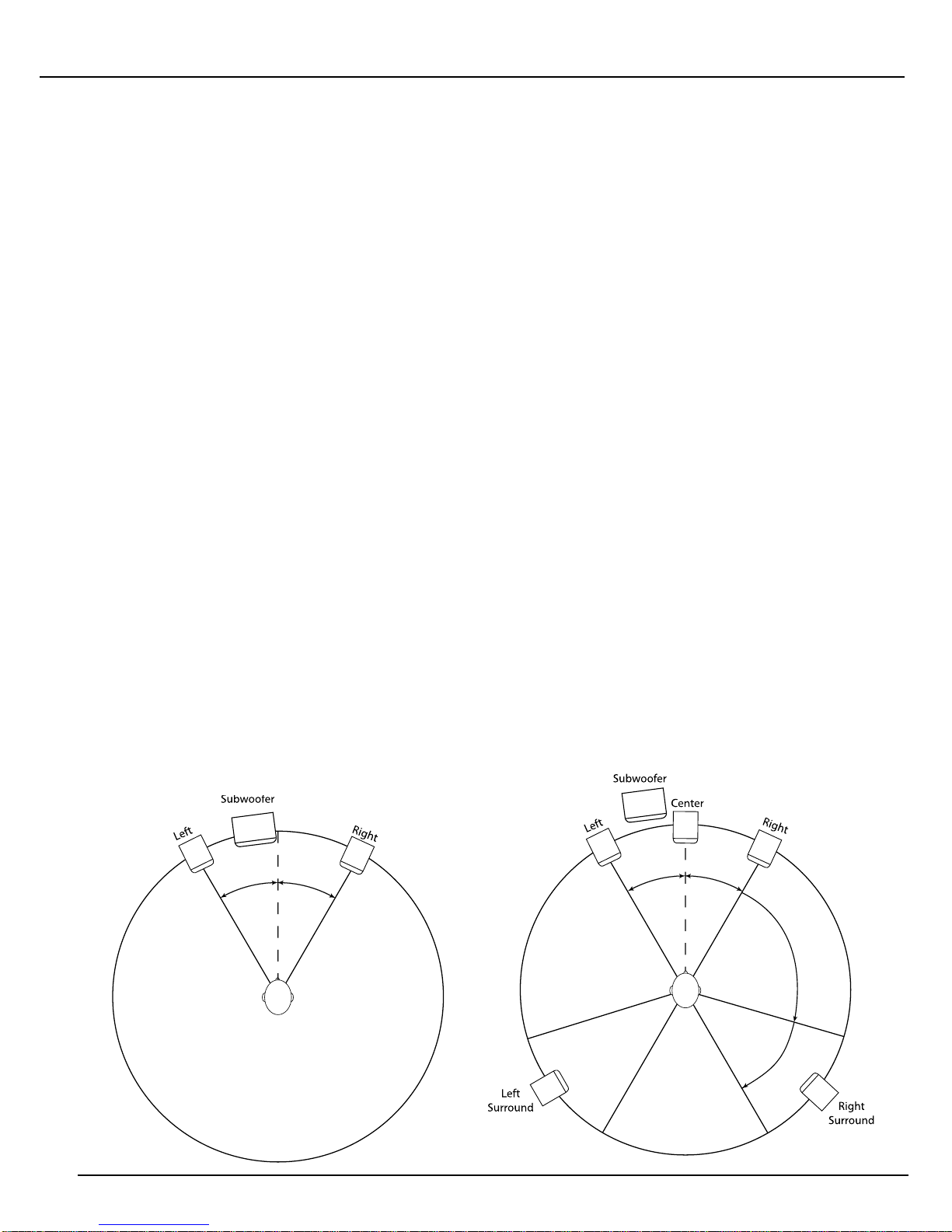
• A JBL Elliptical Oblate Spheroidal (EOS) Waveguide is precisely engineered to achieve smooth mid and
high frequency response for a targeted listening window of ±30º horizontally and ±15º vertically. This
provides greater accuracy at the mix position where the blend of on-axis and reected off-axis sound is
critical. The Elliptical High Frequency Aperture around the tweeter optimizes high frequency coverage for
smoother in-room response above 9kHz
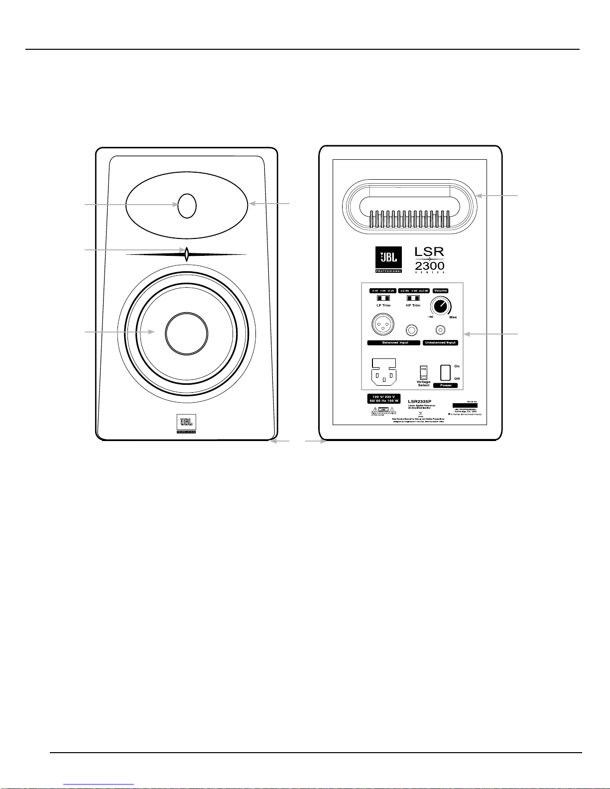
• The LSR2300 series models include balanced XLR, 1/4" and unbalanced RCA connectors, and a variable
level attenuator to allow interface to a broad range of signal sources.
• High Frequency and Low Frequency Trim controls in the LSR2328P and LSR2325P allow adjustment
of frequency response to preference, or to compensate for acoustically reective or absorptive listening
environments.
• LSR2328P and LSR2325P have integrated mounting points and reinforced enclosures to allow safe wall
mounting using readily available, industry-standard mounting brackets.
• The LSR2310SP Subwoofer incorporates a professional bass management system with selectable cross-
over settings to optimize low frequency performance in a range of production environments.
• When added to your LSR2300 System, the optional JBL MSC1 Monitor System Controller provides control
of your system and JBL RMC™ Room Mode Correction – JBL’s ingenius technology that measures and
automatically compensates for the effect of low frequency room modes at the mix position that have
plagued mix engineers. More information about the JBL MSC1 Monitor System Controller is available at
on the JBL Professional Website
To get the most out of your JBL LSR2300 system, please review this owner’s manual and keep it on hand for
future reference. Also, please register your new speakers at www.jblpro.com/registration .

6
Section 3: Setting Up Your System
Unpacking
When removing the systems from their packaging, it is important not to grasp the units from the front. Because the
high frequency device is located near the top of the cabinet on the front bafe, a stray hand or nger can cause
damage. The best way to safely unpack your monitors is to open the top of the box, keep the foam end-cap piece on,
and roll the box upside down. The box can then be slipped off. This also works in reverse for repacking the units.
Placement
IThe LSR2328P and LSR2325P models are designed to be positioned vertically to allow the woofer and the tweeter to
be in vertical alignment. This orientation eliminates phase shift that occurs when the distance of the woofer to the ear
is a different from the distance of the tweeter to the ear. Also, the tweeter waveguide is designed to provide optimum
dispersion when the system is vertically oriented. Placing the system horizontally will defeat the LSR Linear Spatial
Reference principles and cause destructive reection off the work surface. The loudspeakers should be angled so the
center of the high-frequency transducer in each speaker is aimed directly towards the ear of the listener. Ideally, the
LSR2328P and LSR2325P speakers should be placed on suitable speaker stands, rather than on the work surface, and
positioned away from walls and boundaries. The distance and position of the subwoofer can be adjusted to produce
best bass response in the room. Low frequency performance in the room can benet by placing the subwoofer close to
a wall or in a corner that may be further away from the mix position than the other speakers. When properly placed, you
should not be able to localize the bass produced by the subwoofer. That is, your ear should believe the bass is coming
from the Left and Right speakers.
In two channel production applications, the common listening distance is generally 1 to 1.5 meters (3 to 5 feet) from
the left and right speakers. The speakers should be placed so the position of the listener and the two speakers form
an equilateral triangle. In 5.1 Surround Sound production, the listening distance for all speakers from any speaker is
typically 5' to 8'. The placement of the Left and Right speakers should form an equilateral triangle with the mix position.
The Center speaker should be placed half way between the left and right speakers at exactly the same distance from
the mix position. The Left Surround and Right Surround speakers should be placed the same distance as the Left,
Center and Right speakers, and positioned 110 degrees to 150 degrees relative to the center speaker. The distance
and position of the subwoofer can be adjusted to produce best bass response in the room.
30º
30º
30º
30º
110º
150º
110º
150º
Mix Position
2 Channel System with
Subwoofer
5.1 Surround Sound
System

7
Audio Connections
The LSR2300 Series Speakers are equipped with balanced XLR and 1/4" TRS connectors and unbalanced
RCA connectors for connection of professional computer audio interfaces, mixing consoles and audio production
equipment as well as unbalanced consumer audio products including personal music players, consumer audio
receivers and audio visual equipment.
Connect professional equipment with balanced outputs to the XLR or ¼" TRS input of the speaker using balanced
signal cables. (More information is available www.jblpro.com/lsr click on support.)
Connect consumer equipment with unbalanced outputs to the RCA input of the speaker.
The volume control on the rear of the speaker should be set to achieve the comfortable listening level when the
signal source is playing at it’s loudest volume. Positive voltage to Pin 2 of the XLR connector, the tip of the 1/4"
TRS jack, and the RCA jack will produce a forward motion in the low frequency cone.
Power Connections
The LSR2300 Models include a rear panel voltage selector switch that is set at the factory for the appropriate
voltage. Before connecting the power cable it is a good idea to check the position of this switch to conrm the
voltage switch is correctly set for the country of use. The power connector on the speaker includes a user-
replicable protective fuse. The ground terminal of the IEC plug is required by wiring codes and regulations and
must always be connected to the electrical installation safety ground. The LSR2300-Series units have carefully
designed internal grounding and balanced inputs and outputs to reduce the possibility of ground loops that
produce hum. If hum occurs, see Appendix A for suggested audio signal wiring, system grounding hints and
other preventive measures.
Making Sound
After connections are made, reduce the level of the monitor outputs of your console or preamp to minimum and
turn on the powered speakers. Then power-up all audio equipment before powering up the LSR2300 speakers.
When the Blue LED on the front of each turns on, the units are ready to reproduce audio signals. Slowly advance
the volume control of connected audio equipment to achieve a suitable listening level, and enjoy.

8
Section 4: LSR2328P and LSR2325P Bi-amplied Studio Monitors
Front View Back View
Features
1. High Frequency Transducer “Tweeter” – Reproduces high frequency signals
2. EOS Elliptical Oblate Spheroidal Wave Guide with Elliptical Tweeter Aperture – Ensures the combination
of direct and reected sound arriving at the mix position is neutral and accurate. The Elliptical Aperture
opening in the wave guide around the tweeter optimizes high frequency performance above 10 kHz.
3. Low Frequency Transducer “Woofer” – Reproduces low frequency content of the input signal
4. Power Indicator – Illuminates when power is connected and the Power Switch is set to ON.
5. Low Frequency Port – Works in conjunction with the low frequency transducer to provide accurate low
frequency performance and air ow to cool the internal electronics.
6. Input Panel – Includes input connectors, power connector and user controls.
7Isolation Pad – The speaker is equipped with a foam pad on the bottom surface to provide acoustic
isolation from the supporting surface and increase stability when the speaker is placed on a speaker
stand or console top.
5
6
2
1
4
3
7

9
Input Panel
8. XLR Input – Connect professional equipment using and XLR connector
9. ¼" Input - Connect equipment using a ¼" balanced or unbalanced connector
10. RCA Input – Connect consumer equipment using an RCA input.
11. Volume Control – Use this control to Set the maximum listening level
12. High Frequency Trim – Allows boost or cut of High Frequency output by +/- 2.5dB
13. Low Frequency Trim – Allows a 2 dB boost of low frequency output by or 3 dB attenuation of
low frequency output.
14. Power Connector –
15. Fuse Holder – Includes a user replaceable fuse and a spare fuse.
16. Voltage Selector – sets the operating voltage for compatibility with the voltage supply in the country of use
17. Power Switch – Activates power for the system.
Audio Connections
Connect Professional +4dBu and -10 dBV signal sources to either the XLR or ¼" input connectors. Connect
consumer -10dBV level equipment to the RCA input connectors. Connect only a single signal source to the speaker
using either XLR input connector, OR the ¼" TRS input connector OR the RCA input connector. Do not connect
multiple signal sources to multiple inputs of the same speaker simultaneously.
110
78
9
10
11
12
13
14 15
16
LF Trim
HF Trim

10
Section 5: LSR2310SP Powered Studio Subwoofer
Front View Back View
Features
1. Low Frequency Transducer “Woofer” – Reproduces low frequency signals
2. Protective Grille – Protects the woofer when the subwoofer is placed in a location where the woofer could
be damaged by feet, or objects.
3. Power Indicator – Illuminates when power is connected and the Power Switch is set to ON.
4. Feet – Elevates the Subwoofer to prevent acoustic coupling with the oor and prevent scratching of the
enclosure.
5. Low Frequency Port / Low Frequency Port – Works in conjunction with the low frequency transducer to
provide accurate low frequency performance and air ow to cool the internal electronics
6. Input Panel - Includes input connectors, power connector and user controls.
5
6
2
1
4
3

11
Input Panel
7. XLR Left and Right Inputs -
8. ¼" Left and Right Inputs
9. RCA Left and Right Inputs
10. XLR Left and Right Outputs
11. Crossover Frequency Selector – Allows selection of the crossover frequency: 80Hz, 120Hz or using the
External setting enables use of an outboard bass management crossover.
12. Polarity Switch – Enables optional 180 degree reversal of the subwoofer output to optimize the blend of
the subwoofer with the main speakers.
13. Volume Control – Controls the subwoofer level to balance the subwoofer with the system.
14. Power Connector
15. Fuse Holder – Includes a user replaceable fuse and a spare fuse.
16. Voltage Selector – sets the operating voltage for compatibility with the voltage supply in the
country of use
17. Power Switch – Activates power for the subwoofer
Audio Connections
Two Channel Stereo Systems: Connect the Left and Right outputs of the signal sources directly to the Left and
Right Inputs of the LSR2310SP Subwoofer. Then connect the Left and Right Outputs of the Subwoofer to the Left
and Right main speakers.
Using the LSR2310SP in a Surround Sound System – If theLSR2310SP Subwoofer is being used to reproduce
the .1 LFE channel in a surround sound system, connect the .1 LFE signal to either the Left or Right input of the
subwoofer.
Connect Professional +4dBu and -10 dBV signal sources to either the XLR or ¼" input connectors. Connect
consumer -10dBv level equipment to the RCA input connectors. Connect only a single signal source to to the Left
Input and a single signal source to the Right Input of the subwoofer using either XLR input connectors, OR ¼"
input connectors OR the RCA input connectors. Do not connect multiple signal sources to either the Left inputs of
the subwoofer or multiple input sources to the Right inputs simultaneously.
7
8
9
10 11 12
13
14
15
16
17

12
Setting the Subwoofer Level
When the LSR2310SP Subwoofer is used in a system with LSR2328P or LSR2325 speakers, the ideal balance
is achieved when the position of the volume control on the subwoofer is set to the same position as the volume
control on the main speakers. However, if more or less subwoofer volume is desired, you may use the volume
control on the subwoofer to achieve the balance that works best for your application and taste.
Placement and Polarity Setting
Because the human ear cannot easily recognize where low frequencies are originating from (they are said to
be “non-directional”), subwoofer placement is not nearly as critical as main channel speaker positioning. The
LSR2310SP is designed to be placed directly on the oor and not elevated or mounted in any way. Set this
switch to the setting that yields a stronger perceived bass response at the mix position.
The subwoofer should optimally be placed somewhere between the two main speakers. Precise central
placement is not necessary. Centered positioning in the room can sometimes cause unwanted cancellation, so
it is recommended that the subwoofer be slightly placed off-center and not at the midpoint between the left and
right walls.
Ideally, the subwoofer should be placed somewhere near, or behind, the front Center channel speaker.
Crossover Settings and “Bass Management”
“Bass management” is a term that refers to the practice of using a subwoofer to reproduce the bass frequencies
of the main channels. Because of the physiology of the human ear, low frequencies are largely non-directional.
Given an adequate listening distance, we can’t easily tell where bass signals are coming from. Thus, it makes little
or no difference to the listening experience whether the bass component in a sound comes from the originating
speaker (which may be off to your left or right, or even behind you) or from a dedicated subwoofer which is better
equipped – and better positioned in the room – to reproduce low frequencies than even a full-range monitor. For
that reason, you may want to use an LSR2310SP subwoofer to reproduce all the bass frequencies in your system.
If you are using an LSR2310SP Subwoofer in your system, bass management is accomplished simply by routing
your Left and Right mix channels to the Subwoofer inputs and then from the subwoofer outputs to the Left and
Right speakers. The frequency at which the Subwoofer divides signals to the sub and the left and right speakers
can be set using the Crossover Frequency selector switch on the input panel of the LSR2310SP Subwoofer.
Normally this should be set to 80Hz. Two additional settings are provided:
120Hz: Many home theater and music playback systems include small speakers that are unable to reproduce low
frequencies without the help of a subwoofer. In these systems, the receiver engages electronic bass management
to direct low frequency content in the main channels to the subwoofer. The LSR2310SP Subwoofer includes a
120 Hz crossover setting to simulate the sound a listener might hear at home, using a system with small speakers
and a subwoofer.
External: Select this setting when connecting the subwoofer to the JBL MSC1 Monitor System Controller or an
external bass management system.
Surround Sound Systems and LFE
The LSR2310SP Subwoofer can be used to reproduce the LFE (Low Frequency Effects) or .1 channel in a
surround sound system. In lm production applications, the LFE channel contains low frequency effects, such
as the sounds of explosions, and other sounds with strong low frequency components. In music applications, the
LFE channel usually contains low frequency instruments such as bass, bass drum, and synthesizer elements.

13
Section 6: System Connections
Two Channel Systems
.
LEFT CHANNEL
SPEAKER RIGHT CHANNEL
SPEAKER
SUBWOOFER
MIXER
LEFT OUT RIGHT OUT

14
Section 6: System Connections
Two Channel Systems with MSC Monitor System Controller
LEFT CHANNEL
SPEAKER RIGHT CHANNEL
SPEAKER
SUBWOOFER
COMPUTER AUDIO
SYSTEM MIXER
MP3 PLAYER
HEADPHONES
MSC1

15
Section 6: System Connections
Surround Sound Systems
SUBWOOFER
COMPUTER AUDIO
WORK STATION
LEFT CHANNEL
SPEAKER RIGHT CHANNEL
SPEAKER
LEFT SURROUND
SPEAKER RIGHT SURROUND
SPEAKER
CENTER
SPEAKER
COMPUTER AUDIO
INTERFACE

16
Section 8: Appendix A
Mounting Specications for LSR2328P and LSR2325P
Mounting points are provided for use with industry-standard mounting brackets. Mounting points are located on
the bottom of the LSR2328P and LSR2325P models.
Fastener specications:
Type: M6 metric thread
Length: 1 inch (25.4 mm) plus the thickness of the mounting plate.
Hole Pattern:
1/4 Inch
107.9 mm
(4.25 in)
50.8 mm
(2 in)
Caution: Unsafe mounting or overhead suspension of any heavy load can result in serious injury and equipment
damage. Mounting of speakers should be done by qualied persons in accordance with all applicable local safety
and construction standards. Be certain to follow the instructions provided by the manufacturer of the mounting
bracket, be certain that it is capable of supporting the weight of the speaker to be mounted.

17
Section 9: Appendix B
Trouble Shooting
If there is no sound from your speakers, check these settings:
• Make sure a signal source is connected and producing sound.
• Make sure the blue power ON LED is illuminated on the front of the speaker.
• Make sure the volume control is not set to the full counter clockwise position.
• Conrm the power cable is connected and the power switch is set to the ON position.
•If the blue LED on the front of the speaker does not illuminate, examine the fuse for possible failure of the fuse.
Turn the Power Switch to the OFF position. Remove the power cord, and remove the fuse holder as illustrated.
Examine the fuse. If the fuse has a discontinuity in the internal wire or the fuse glass has dark spots as evidence
the fuse has failed, install a new using the spare included in the fuse holder. Replace the fuse holder and try to
re-power the system. If the system does not re-power, please contact JBL Professional Customer Service.
•When using the LSR2310SP Subwoofer: If the system sounds as if it lacks low frequency conrm the subwoofer
is powered ON and the volume control is not set to full counter clockwise setting.
If the above measures do not correct the problem, please contact JBL Professional Customer Service.

18
Section 9: Appendix B
Specications
LSR2328P LSR2325P LSR2310SP
Frequency Response: (+3, -3 dB) 53 Hz – 18 kHz (+3, -3 dB) 60 Hz - 18 kHz (-6 dB) 36 Hz - 85 Hz
Low Frequency Extension (-10dB): 37 Hz 43 Hz 29 Hz
Low-High Frequency Crossover: 2.0 kHz 4th-order acoustic Linkwitz-
Riley
1.7 kHz 4th-order acoustic Linkwitz-Riley
Maximum Continuous SPL each / Per Pair
@ 1m >103 dB SPL / >109dB SPL >99 dB SPL / >105dB SPL >102 dB SPL (35Hz-80Hz)
Maximum Peak SPL Each/ Per Pair @ 1m >117 dB / >123 dB SPL / 1m >112 dB / >118 dB SPL / 1m 113 dB
Input Connectors: Balanced XLR, 1/4" tip-ring-sleeve
and unbalanced RCA. Positive voltage
applied to XLR pin 2 , 1/4" tip, RCA pin
produces outward woofer motion
Balanced XLR, 1/4" tip-ring-sleeve and
unbalanced RCA. Positive voltage applied
to XLR pin 2 , 1/4" tip, RCA pin produces
outward woofer motion
L&R: Balanced XLR (2), 1/4" tip-ring-sleeve
(2) and unbalanced RCA (2). Positive voltage
applied to XLR pin 2 , 1/4" tip, RCA pin
produces outward woofer motion
Calibrated Input Sensitivity, XLR & 1/4":-
10dBV
96 dB SPL / 1 m 96 dB SPL / 1 m 96 dB SPL / 1 m (80 Hz BM)
RCA Input:-20dBV 96 dB SPL / 1 m 96 dB SPL / 1 m 96 dB SPL / 1 m (80 Hz BM)
Output: Connectors: - - - - - - L&R: Balanced XLR (2), 1/4" tip-ring-
sleeve (2).
AC Input Voltage: 115 / 230 VAC, 50/60 Hz 115 / 230 VAC, 50/60 Hz 115 / 230 VAC, 50/60 Hz
AC Input Voltage Operating Range +/- 15% +/- 15% +/- 15%
AC Input Connector: IEC with User Replaceable Fuse IEC with User Replaceable Fuse IEC with User Replaceable Fuse
Replaceable Fuse Type (120 Volt / 240
Volt)
4 amp Time Lag 250V/ 2 amp Time
Lag 250V
4 amp Time Lag 250V/ 2 amp Time Lag
250V
5 amp Time Lag 250V/ 2.5 amp Time Lag
250V
Long-Term Maximum System Power: 100 watts (IEC265-5) 22 watts (IEC265-5) 150 watts (IEC265-5)
Controls:
Volume Range -innity dB - 0 dB -innity dB - 0 dB -innity dB - 0 dB
High Frequency Control (7 kHz Shelving): +2.5 dB, 0 dB, -2.5 dB +2.5 dB, 0 dB, -2.5 dB - - -
Low Frequency Control (120 Hz Shelving): +2.0 dB, 0 dB, -3.0 dB +2.0 dB, 0 dB, -3.0 dB - - -
Crossover Frequency 80 Hz, 120 Hz, External
Transducers:
Low Frequency Model: 238G 235G 230H
Diameter: 203 mm (8 in) 132 mm (5.2 in) 254 mm (10 in)
Voice Coil: 38 mm (1.5 in) 25 mm (1.0 in) 51 mm (2.0 in)
Magnet Type: Magnetically Shielded Ferrite Magnetically Shielded Ferrite Magnetically Shielded Ferrite
Cone Type: Tempered Paper with Butyl Rubber
Compliance
Tempered Paper with Butyl Rubber
Compliance
Tempered Paper with Butyl Rubber
Compliance
Impedance: 4 ohms 4 ohms 8 ohms
High Frequency Model: 231H 231H - - -
Diameter: 25 mm (1 in) diaphragm 25 mm (1 in) diaphragm - - -
Magnet Type: Neodymium Neodymium - - -
Diaphragm Type: Silk Substrate with Epoxy Silk Substrate with Epoxy - - -
Other Features: EOS Elliptical Oblate Spheroidal
waveguide with Elliptical Aperture
EOS Elliptical Oblate Spheroidal
waveguide with Elliptical Aperture
- - -
Impedance: 8 ohms 8 ohms - - -
Amplier:
Low Frequency:
Topology: Class A-B, monolithic Class A-B, monolithic Bridged Class A-B, monolithic
Sine Wave Power Rating: 95 watts (<0.1% THD into rated
impedance)
50 watts (<0.1% THD into rated
impedance)
180 watts (<0.1% THD into rated
impedance)
THD + N, H Power: <0.03% <0.01% <0.05%
High Frequency:
Topology: Class A-B, monolithic Class A-B, monolithic - - -

19
Section 9: Appendix B
Specications (Continued)
Sine Wave Power Rating: 70 watts (<0.1% THD into rated
impedance)
35 watts (<0.1% THD into rated
impedance)
- - -
THD + N, H Power: <0.07% <0.05% - - -
Physical:
Finish: Bafe: Metallic Anthracite Paint Bafe: Metallic Anthracite Paint Bafe: Metallic Anthracite Paint
Enclosure: Matte Black PVC Enclosure: Matte Black PVC Enclosure: Matte Black PVC
Mounting: 4 threaded mounting points conforming
to Industry-standard pattern, 107.9 x
50.8 mm (4.25 x 2.00 in) center to center.
M6 metric threads.
4 threaded mounting points conforming to
Industry-standard pattern, 107.9 x 50.8 mm
(4.25 x 2.00 in) center to center. M6 metric
threads.
- - -
Enclosure Volume (net): 13 liter (0.46 cu ft) 7.1 liter (0.25 cu ft) 34 liter (1.2 cu ft)
Low Frequency Vent: Rear ported ---- (integrated with
amplier heat sink)
Rear ported ---- (integrated with amplier
heat sink)
Rear ported ---- (integrated with amplier
heat sink)
Bafe Construction: Injection-molded structural ABS Injection-molded structural ABS Injection-molded structural ABS
Enclosure Construction: 18 mm (3/4 in) MDF 15 mm (5/8 in) MDF 18 mm (3/4 in) MDF
Net Weight: 12.3 kg (27 lb) 6.8 kg (15 lb) 20.2 kg (44.5 lb)
Dimensions (H x W x D): 397 x 254 x 335 mm (15.6 x 10 x
13.19 in)
303 x 187 x 258 mm (11.9 x 7.4 x 10 in) 414 x 381 x 460 mm (16.3 x 15 x 18.1 in)
Topology: Class A-B, monolithic Class A-B, monolithic - - -
Sine Wave Power Rating: 70 watts (<0.1% THD into rated
impedance)
35 watts (<0.1% THD into rated
impedance)
- - -
THD + N, H Power: <0.07% <0.05% - - -
Physical:
Finish: Bafe: Metallic Anthracite Paint Bafe: Metallic Anthracite Paint Bafe: Metallic Anthracite Paint
Enclosure: Matte Black PVC Enclosure: Matte Black PVC Enclosure: Matte Black PVC
Mounting: 4 threaded mounting points conforming
to Industry-standard pattern, 107.9 x
50.8 mm (4.25 x 2.00 in) center to center.
M6 metric threads.
4 threaded mounting points conforming to
Industry-standard pattern, 107.9 x 50.8 mm
(4.25 x 2.00 in) center to center. M6 metric
threads.
- - -
Enclosure Volume (net): 13 liter (0.46 cu ft) 7.1 liter (0.25 cu ft) 34 liter (1.2 cu ft)
Low Frequency Vent: Rear ported ---- (integrated with
amplier heat sink)
Rear ported ---- (integrated with amplier
heat sink)
Rear ported ---- (integrated with amplier
heat sink)
Bafe Construction: Injection-molded structural ABS Injection-molded structural ABS Injection-molded structural ABS
Enclosure Construction: 18 mm (3/4 in) MDF 15 mm (5/8 in) MDF 18 mm (3/4 in) MDF
Net Weight: 12.3 kg (27 lb) 6.8 kg (15 lb) 20.2 kg (44.5 lb)
Dimensions (W x H x D): 397 x 254 x 335 mm (15.6 x 10 x
13.19 in"
303 x 187 x 258 mm (11.9 x 7.4 x 10 in) 414 x 381 x 460 mm (16.3 x 15 x 18.1 in)

20
Section 10: Contact Information
Mailing Address:
JBL Professional
8500 Balboa Blvd.
Northridge, CA 91329
Shipping Address:
JBL Professional
8370 Balboa Blvd., Dock D
Northridge, CA 91329
(Do not return product to this address without rst obtaining prior authorization from JBL)
Customer Service:
Monday through Friday
8:00am -5:00pm
Pacic Coast Time in the U.S.A.
(800) 8JBLPRO (800.852.5776)
www.jblproservice.com
Product Registration:
Register your product online at www.jblpro.com/registration
On The World Wide Web:
www.jblpro.com
Professional Contacts, Outside the USA:
Contact the JBL Professional Distributor in your area. A complete list of JBL Professional international distributors is
provided at our U.S.A. website: www.jblpro.com
En Dehors des Etats-Unis:
Contacter votre Distributeur JBL Professional. Une liste complète de nos distributeurs internationaux est disponible
sur le site web - www.jblpro.com
International:
Wenden Sie sich an Ihre örtliche JBL Professional Vertretung. Eine vollständige Liste der internationalen JBL-
Vertretungen nden Sie auf userem Website unter www.jblpro.com
Fuera de los Estados Unidos:
Comuníquese con el distribuidor de JBL Professional de su zona. En nuestro sitio web, www.jblpro.com, encontrará
una lista completa de los distribuidores de JBL International.
Other manuals for LSR2325P
1
This manual suits for next models
2
Table of contents
Other JBL Speakers manuals