JBL VerTec DP Series Specification sheet

Product User’s Guide
Compact Powered Line Array Systems
VT4887ADP
VT4887ADP-DA
VT4887ADP-AN
VT4887ADP-CN
VT4881ADP
VT4881ADP-DA
VT4881ADP-AN
VT4881ADP-CN
www.audiovias.com

2VERTEC User’s Guide
www.audiovias.com

3
JBL Professional
Section 1. Safety Instructions.....................................................................................Page 4
Section 2. Before You Begin .......................................................................................Page 7
Section 3. Introduction to VERTEC®DP Series
Compact Powered Line Array Systems...................................................Page 8
Specications by model
Section 4. VERTEC® DP Series Transducers.............................................................Page 10
Section 5. Enclosure Care and Maintenance ............................................................Page 11
Section 6. Suspension.................................................................................................Page 12
Safety Precautions
Industry Resources
Section 7. JBL DrivePack® Technology ....................................................................Page 15
AC Power Module, Electrical Information
Input Modules (DPIP, DPDA, DPAN, DPCN)
Protective Jackets & installation
Section 8. HiQnet System Architect™ Software Configuration Guide ...................Page 28
Conguring your PC
Ethernet Network connections
Appendix A: Conguring CobraNet devices
Appendix B: Setting Microsoft Windows to standard font size
Appendix C: Setting Regional Language Options to US English
Section 9. JBL Professional Warranty .......................................................................Page 39
Section 10. Factory Contact Information ....................................................................Page 40
TABLE OF CONTENTS
www.audiovias.com

4VERTEC User’s Guide
SECTION 1 : SAFETY INSTRUCTIONS
Important
1. Read these instructions.
2. Keep these instructions.
3. Heed all warnings.
4. Follow all instructions.
5. Do not use this apparatus near water.
6. Clean only with dry cloth.
7. Do not block any ventilation openings. Install in accordance with the manufacturer’s instructions.
8. Do not install near any heat sources such as radiators, heat registers, stoves, or other apparatus
(including ampliers) that produce heat.
9. Do not defeat the safety purpose of the polarized or grounding-type plug. A polarized plug has
two blades with one wider than the other. A grounding-type plug has two blades and a third
grounding prong. The wide blade or the third prong are provided for your safety. If the provided
plug does not t into your outlet, consult an electrician for replacement of the obsolete outlet.
10. Protect the power cord from being walked on or pinched, particularly at plugs, convenience
receptacles, and the point where they exit from the apparatus.
11. Only use attachments/accessories specied by the manufacturer.
12. Use only with the cart, stand, tripod, bracket, or table specied by the manufacturer, or
sold with the apparatus. When a cart is used, use caution when moving the cart/apparatus
combination to avoid injury from tip-over.
13. Unplug this apparatus during lightning storms or when unused for long periods of time.
14. Refer all servicing to qualied service personnel. Servicing is required when the apparatus has
been damaged in any way, such as power supply cord or plug is damaged, liquid has been
spilled or objects have fallen into the apparatus, the apparatus has been exposed to rain or
moisture, does not operate normally, or has been dropped.
15. WARNING: To reduce the risk of re or electric shock, do not expose this apparatus
to rain or moisture.
16. Do not expose this equipment to dripping or splashing and ensure that no objects lled with
liquids, such as vases, are placed on the equipment.
17. To completely disconnect this apparatus from the AC Mains, disconnect the power supply
cord plug from the AC receptacle.
18. The mains plug of the power supply cord shall remain readily operable.
www.audiovias.com

5
JBL Professional
THIS APPARATUS CONTAINS POTENTIALLY LETHAL VOLTAGES. TO PREVENT ELECTRIC SHOCK OR
HAZARD, DO NOT REMOVE DRIVEPACK CHASSIS, INPUT MODULE OR AC INPUT COVERS. NO USER
SERVICEABLE PARTS INSIDE. REFER SERVICING TO QUALIFIED SERVICE PERSONNEL.
WATCH FOR THESE SYMBOLS
The lightning bolt triangle is used to alert the user to the risk of electric shock.
The exclamation point triangle is used to alert the user to important operating or
maintenance instructions.
FCC COMPLIANCE NOTICE
This device complies with part 15 of the FCC rules. Operation is subject to the following two conditions: (1)
This device may not cause harmful interference, and (2) this device must accept any interference received,
including interference that may cause undesired operation.
CAUTION: Changes or modications not expressly approved by the party responsible for compliance could
void the user’s authority to operate the equipment.
CSA COMPLIANCE NOTICE
CSA Certication Applies to Amplier Module Only
#!54)/.
2)3+/&%,%#42)#3(/#+
$/./4/0%.
www.audiovias.com

6VERTEC User’s Guide
JBL DRIVEPACK®DECLARATION OF CONFORMITY
Safety and EMC Compliance Specifications
EN 55103-1:1997 Electromagnetic Compatibility - Product Family Standard for Audio, Video, Audio-
Visual and Entertainment Lighting Control Apparatus for Professional Use, Part 1: Emissions
EN 55103-1:1997 Magnetic Field Emissions-Annex A @ 10 cm and 1 M
EN 55022:2003 Limits and Methods of Measurement of Radio Disturbance Characteristics of ITE:
Radiated, Class B Limits; Conducted, Class A
EN 55103-2:1997 Electromagnetic Compatibility - Product Family Standard for Audio, Video, Audio-
Visual and Entertainment Lighting Control Apparatus for Professional Use, Part 2: Immunity
EN 61000-4-2:1995 + A1:1999 & A2:2001 Electrostatic Discharge Immunity (Environment E2-criteria B, 4
kV Contact, 8 kV Air discharge)
EN 61000-4-3:2003 Radiated, Radio-frequency, Electromagnetic Immunity (Environment E2, criteria A)
EN61000-4-4:2005 Electrical Fast Transient/Burst Immunity (criteria B)
EN 61000-4-5:2001 Surge Immunity (criteria B)
EN 61000-4-6:1996 Immunity to Conducted Disturbances Induced by Radio-Frequency Fields (criteria A)
EN 61000-4-11:2004 Voltage Dips, Short Interruptions and Voltage Variation
UL 60065:2003, 7th edition: Audio/Video and Musical Instrument Apparatus for Household, Commercial
and Similar General Use
IEC 60065, 2001: Audio, Video and Similar Electronic Apparatus - Safety Requirements
CAN/CSA E60065-03: Audio, Video and Similar Electronic Apparatus – Safety Requirements
www.audiovias.com

7
JBL Professional
SECTION 2 : BEFORE YOU BEGIN
The VERTEC®DP Series systems covered by this manual are not intended for xed installation
in outdoor or high moisture environments. Moisture can damage the speaker cone and surround
and cause corrosion of electrical contacts and metal parts. Avoid exposing the speakers to direct
moisture. Keep loudspeakers out of extended or intense direct sunlight. The driver suspension will
prematurely dry out and nished surfaces may be degraded by long-term exposure to intense ultra-
violet (UV) light.
VERTEC® DP Series Compact Powered Line Array loudspeakers can be suspended with available
array frames (P/N VT4887-AF, VT4887-SF) or they can be ground-stacked. These systems can
generate considerable energy. When placed on a slippery surface such as polished wood or
linoleum, a single speaker may move due to its acoustical energy output. Precautions should be
taken to assure that the speaker does not fall off a stage or scaffold platform on which it is placed.
While it is unlikely that a ground-stacked array will move when properly attached to its array frame,
precautions should be taken to assure that the array assembly cannot fall from any surface on
which it is placed. Hearing damage, prolonged exposure to excessive SPL VERTEC® DP Series
loudspeakers are easily capable of generating sound pressure levels (SPL) sufcient to cause
permanent hearing damage to performers, production crew and audience members. Caution should
be taken to avoid prolonged exposure to SPL in excess of 90 dB.
Package Contents
• Product User’s Guide (this document)
• JBL DrivePack® compatible loudspeaker
• CD containing System Architect™ software
• AC Power North America/Europe Cord-Set
• Protective Jacket Set
• Warranty Card
www.audiovias.com

8VERTEC User’s Guide
SECTION 3 : INTRODUCTION TO VERTEC®DP SERIES
COMPACT POWERED LINE ARRAY SYSTEMS
Shown: VT4881ADP over VT4887ADP
VERTEC®DP Series Compact Powered Systems
The VERTEC DP Series compact models are part of a family of powered integrated audio loudspeaker
systems featuring the JBL DrivePack® amplier modules, designed in cooperation with Crown International.
The JBL DrivePack features cutting-edge technology such as patented high efciency Class-I power
amplier circuitry. Loudspeaker components include patented JBL Differential Drive® woofers.
This guide covers the following models:
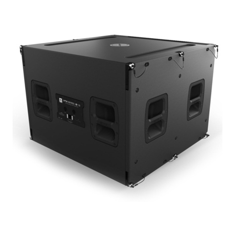
VT4881ADP..........................1x18” subwoofer system
VT4881ADP-DA...................DPDA network input module, AES digital audio
VT4881ADP-AN...................with optional DPAN network input module, analog audio
VT4881ADP-CN...................with optional DPCN network input module, Cobranet™ digital audio
VT4887ADP..........................2x8” bi-amplied three-way full range system
VT4887ADP-DA...................DPDA network input module, AES digital audio
VT4887ADP-AN...................with optional DPAN network input module, analog audio
VT4887ADP-CN ..................with optional DPCN network input module, Cobranet™ digital audio
www.audiovias.com

9
JBL Professional
VERTEC DP SERIES, COMPACT POWERED SYSTEMS SPECIFICATIONS
Product Acoustics VT4887ADP VT4881ADP
Frequency Response (±3 dB): 67 Hz – 20 kHz 34 Hz - 125 Hz
Frequency Range (-10 dB): 55 Hz – 22 kHz 25 HZ - 160 Hz
Horizontal Coverage
Angle (-6 dB): 100 deg. nominal (500 Hz – 16 kHz) N/A
Vertical Coverage
Angle (-6 dB): Varies with array size and conguration N/A
Maximum Peak Output: 136 dB SPL, 1m 131 dB SPL, 1m
Transducer Sections
Low Frequency Two 2168H-1, 203 mm (8 in) dia., 76 mm
(3 in) Dual Coil, Differential Drive®, Direct
Cooled
One 2269G, 457 mm (18 in) dia., 100 mm
(4 in) Dual Coil, Differential Drive®, Direct
Cooled, 2000W Cont./8000W Peak
Bandpass Nominal Impedance: 4 Ohms (LF woofers wired in parallel) 4 Ohms
Mid & High Frequency: MID: Four 2104H 101 mm (4 in) with 25.4 mm
(1 in) dia. voice coil
HF: Two JBL 2408H 25 mm (1 in) exit com-
pression drive, 38 mm (1.5 in) voice coil
N/A
Bandpass Nominal Impedance: 8 ohms (drivers wired in series-parallel) N/A
System Electronics
DP Internal Amplication
Output (at load): DP2; 2200W Peak, 1100W Continuous DP1; 3600W Peak, 1800W Continuous
DP Output Topology: DP2; 2-Channel, Class-I DP1; 1-Channel, Class-I
Signal Processing: dbx Type IV Conversion System, Precision bandpass lters, limiting, pre-equalization
lters and automatic self-test functions
System Management: DSP based limiters for mechanical and thermal protection
Signal Input: F-XLR Active 20K Ohms Balanced, 10K Ohms Unbalanced
Signal Loop-Through: M-XLR (passive pass-through)
Controls: Precision 0.5 dB increment Detented 16 dB input attenuator
AC Power Operating Range: Auto Select 90-132/VAC 50/60 Hz
AC Line Voltage: 50/60 Hz, Auto-Detect; 120V/240V (±10%)
AC Input Connector:
AC Power Loop-thru:
Neutrik PowerCon (Blue)
Neutrik PowerCon (Gray)
AC Current Requirement: 4A per system at 120V, 3A per system at
240V
5A per system at 120V, 3.2A per system
at 240V
Enclosure
Box Construction: Wedge frustum 5 degree side angle enclo-
sure. PlyMax™engineered composite struc-
ture, DuraFlex nish, 2 handles
Rectangular enclosure. PlyMax™ engi-
neered wood composite
structure. DuraFlex™ nish, 6 handles
Suspension System: S.A.F.E. hardware, integral hinge bars nest
in rigging tubes on box ends. Quick release
pins with restraining lanyards
S.A.F.E. hardware, as per VT4887ADP.
Suspend with VT4887-AF Array Frame.
Set of 4 hinge bars included with
VT4881ADP system.
Grille: Black perforated steel, foam backed
Dimensions (W x H x D): 787 mm X 279 mm X 563 mm
(31 in X 11 in X 22.1 in)
787 mm X 569 mm X 800 mm
(31 in X 22.4 in X 31.5 in)
Net Weight: 39.7 kg (87.5 lb) 62.2 kg (137 lb)
www.audiovias.com

10 VERTEC User’s Guide
2408H High Frequency Compression Driver
JBL’s 2408H features a lightweight neodymium magnet structure, annular
polymer diaphragm and a 1” exit. Coupled to a proprietary waveguide
engineered to be part of the system’s thermal-transfer mechanism, it is
designed to deliver crystal-clear sound with superb dynamic range. The
2408H is an 8 Ohm device. Two are included in each VT4887ADP system.
2168H-1 Low Frequency Loudspeaker
The 2168H-1 is an 8” transducer engineered with JBL’s patented
Differential Drive® technology. These low frequency drivers dramatically
reduce driver weight while greatly enhancing all critical performance
parameters: frequency response, power output, and distortion.
Differential Drive technology features a unique design with heat
sinks integrated into the cast aluminum frame for a highly improved
performance to weight ratio. The dual voice coil design places the
neodymium magnets inside the voice coil assembly, completing the
magnetic circuit without the heavy surrounding steel structure of
conventional drivers. 8 Ohm device.
For more information, see JBL Tech Note Vol. 1 Number 33, “Differential
Drive Transducers”
2269G Ultra Long Excursion, Differential Drive®
Low Frequency Drivers
Ultra Long Excursion 460mm (18”) transducer features 2000 watts
continuous (AES), 8000 watts peak power handling capacity. It’s the
latest example of JBL’s patented Differential Drive® dual voice-coil
loudspeaker technology, tted with dual neodymium magnets, JBL’s
exclusive Vented Gap Cooling™, and an ultra-robust composite cone
with a peak-to-peak maximum excursion of 89 mm (3.5”).
SECTION 4 : VERTEC®DP SERIES TRANSDUCERS
www.audiovias.com

11
JBL Professional
SECTION 5 : ENCLOSURE CARE AND MAINTENANCE
PAINTING JBL VERTEC DP SERIES SYSTEM PRODUCTS
VERTEC DP Series enclosures are constructed of JBL PlyMax™, an exclusive hybrid engineered-wood
technology designed to reduce enclosure weight while offering exceptional panel rigidity with the appropriate
acoustical properties. The exterior of each enclosure is covered with JBL’s exclusive DuraFlex™ nish.
Each JBL Professional VERTEC DP Series system model is readily paintable. The DuraFlex nish provides
a lightly textured surface that any household or industrial paint readily adheres to. The result is a speaker
enclosure that is able to blend unobtrusively into the decor of any stage set or environment.
Instructions for painting wood enclosures (do not paint the JBL DrivePack®):
1. Prepare the enclosure surface by cleaning and wiping off dust and lm with a damp cloth. It may be
necessary to use a mild household cleaner to remove grease. Avoid using a cloth that will deteriorate over
the textured surface.
2. Apply as many coats of paint as is required. Application can be by rolling, brushing or spraying. Care must
be taken when painting the grille. Avoid any paint or type of application that will clog the open cells in the
foam of the front grille. Depending on the type of paint, it may not be wise to spray the grille.
3. For painting systems that are installed in environmentally-hostile locations, it is recommended that an
automotive paint should be used for maximum protection.
Note: for systems that will be transported on a regular basis, oil-based paints or Krylon-type spray paints will
give better long-term results than water-based Latex type paints.
www.audiovias.com

12 VERTEC User’s Guide
SECTION 6 : SUSPENSION
Before attempting to suspend your speakers, read and understand the following safety information.
IMPORTANT SAFETY WARNING!
The information in this section has been assembled from recognized engineering data and is intended for
informational purposes only. None of the information in this section should be used without rst obtaining
competent advice with respect to applicability to a given circumstance. None of the information presented
herein is intended as a representation or warranty on the part of JBL. Anyone making use of this information
assumes all liability arising from such use.
All information presented herein is based upon materials and practices common to North America and may
not directly apply to other countries because of differing material dimensions, specications, and/or local
regulations. Users in other countries should consult with appropriate engineering and regulatory authorities
for specic guidelines.
Correct use of all hardware is required for secure system suspension. Careful calculations should always be
performed to ensure that all components are used within their rated workload before the array is suspended.
Never exceed maximum recommended load ratings.
Before suspending any speaker system always inspect all components (enclosure, suspension tubes, pins,
etc.) for cracks, deformations, corrosion, missing, loose or damaged parts that could reduce strength and
safety of the array. Do not suspend the speaker until the proper corrective action has been taken. Use only
load-rated hardware when suspending VERTEC®DP Series loudspeakers.
Safety Precautions
www.audiovias.com

13
JBL Professional
Are You New to Rigging?
If your work with suspended loudspeakers also involves rigging, you should do the following:
• Read and study JBL Technical Note Volume 1, Number 14: Basic Principles for Suspending Loudspeaker
Systems (available at http://www.jblpro.com/pub/technote/tn_v1n14.pdf).
• Know the Rules for Safe Rigging.
• Attend a safe rigging seminar, such as that presented by professionals like Rigging Seminars™ or by
Chain Motor Hoist manufacturers like Columbus McKinnon Corp. (manufacturers of the C/M Lodestar).
• Meet and establish a relationship with a licensed mechanical or structural engineer. Get in the habit of
asking them questions instead of guessing about their answers. Learn from what they tell you.
• Meet and discuss this aspect of your business with your Insurance Agent.
• Research and understand the codes, practices, and requirements in the venues where you intend to
operate your sound system.
General Hardware Information
Any hardware used in an overhead suspension application must be load rated for the intended use.
Generally, this type of hardware is available from rigging supply houses; industrial supply catalogs and
specialized rigging distributors. Local hardware stores do not usually stock these products.
Attachment to Structures
A licensed Professional Engineer must approve placement and method of attachment to structures prior
to installation of any overhead object. The following performance standards should be provided to the
Professional Engineer for design purposes: Uniform Building Code as applicable, Municipal Building Code as
applicable, Seismic Code as applicable. Installation of hardware and method of attachment must be carried
out in the manner specied by the Professional Engineer. Improper installation may result in damage, injury
or death.
Suspension Hardware Inspection & Maintenance
Suspension systems are comprised of mechanical devices and, as such, they require regular inspection
and routine maintenance to insure proper function ability. JBL VERTEC®DP Series loudspeakers must
be inspected for fatigue at least annually. The inspection shall include a visual survey of all corners and
load bearing surfaces for signs of cracking, water damage, de-lamination, or any other condition that may
decrease the strength of the loudspeaker enclosure. Accessory rigging hardware provided with or for JBL
VERTEC DP Series loudspeakers must be inspected for fatigue at least annually. The inspection shall include
a visual material survey for signs of corrosion, bending or any other condition that may decrease strength of
the fastener. For other ttings used, refer to the manufacturer’s inspection and maintenance guidelines for
process.
JBL is not responsible for the application of its products for any purpose or the misuse of this information
for any purpose. Furthermore, JBL is not responsible for the abuse of its products caused by avoiding
compliance with inspection and maintenance procedures or any other abuse. Prior to suspending the
system, an expert, trained and experienced in flying loudspeaker systems should inspect all rigging parts and
components.
www.audiovias.com

14 VERTEC User’s Guide
Allen Products
(562) 424-1100
1635 E. Burnett Street
Signal Hill, CA 90806
www.allenproducts.com
M.A.N. Flying Systems
20 Sidar Road Brook Road
Industrial Estate
Rayleight, Essex SS6 7XF U.K.
www.many.co.uk
JBL Professional - Tech Note V1 No. 14
“Basic Principles for Suspending Loud-
speakers”
www.jblpro.com/technote/tn_v1n14.pdf
ATM Fly-Ware
(562) 424-1100
1635 E. Burnett Street
Signal Hill, CA 90806
www.atmyware.com
McMaster Carr
Various locations through the U.S.A.
For a location near you, visit them online:
www.mcmastercarr.com
Safe Rigging
The JBL VERTEC®DP Series arrayable loudspeakers are equipped with integral suspension hardware and
should only be suspended using the supplied equipment. The system is designed to facilitate the suspension
of the loudspeakers by a qualied person familiar with rigging hardware and industry practices. Improper
installation may result in damage, injury or death.
Working Load Limit
The working load limit (WLL) for any group (“array”) of JBL VERTEC DP Series system products is noted on
the appropriate VERTEC Array Frame.
Industry Resources
VT4887-AF Array Frame
www.audiovias.com

15
JBL Professional
Introduction to the
JBL DrivePack Integrated Audio System
JBL DrivePack equipped loudspeakers are a family of fully integrated audio systems, coupling industry-
leading loudspeaker technology to a combination of comprehensive digital signal processing and advanced
amplier technology, perfectly matched to the enclosures to deliver superb audio quality and powerful
performance.
The DrivePack is attached to the back of each DP-compatible loudspeaker enclosure, creating a seamless
electro-mechanical system that offers both convenience and portability along with the unmatched reliability,
accuracy and superb sound of JBL loudspeakers. The DrivePack includes onboard DSP functionality to
communicate readiness and operational status, including a self-test cycle and lighted indicators for fault
detection upon power-up.
DrivePack Signal-Processing & Amplification Unit
The DrivePack electronics unit is intended to be used when mounted to a speaker enclosure of
5/8” minimum thickness of wood or composite material and with load impedances of 4 Ohms, 8
Ohms for low and mid frequency channels, and 8 or 16 Ohms for the high frequency channel.
OPERATING INSTRUCTIONS
All that is required to get your DP compatible loudspeaker system up and running is to connect an AC power
source to the AC Power module via the Neutrik PowerCon™ inlet connector, and a full range line level audio
signal to the Input module via the AUDIO IN XLR connector.
Upon initial power-up of the DrivePack, the Blue Power LED will illuminate and the Green DP Ready indicator
(located to the left of the input module input level control) will ash during the boot-up and AC line auto-
select soft-start process. The JBL DrivePack is equipped with Auto-Sensing Universal AC Voltage Selection
and can operate anywhere in the world that has an available 100-120VAC or 200-240VAC power source. On
the power-up sequence the JBL DrivePack® input module senses line voltage and sets the high voltage line
select relay within about 2 seconds. The system is ready for operation when the Green Ready LED on both
the AC Input module and DPIP module is steadily illuminated.
SECTION 7 : JBL DRIVEPACK®TECHNOLOGY
www.audiovias.com

16 VERTEC User’s Guide
AC POWER REQUIREMENTS
Standard JBL DrivePack systems are equipped with a DP multi-channel Crown Class-I power amplier and
loudspeaker specic DSP electronics and require appropriate AC power.
CAUTION: In compliance with safety agency criteria and proper system operation, it is critical
that the system installer observe all electrical safety practices at all times and provide proper earth
grounding for all AC Power connections.
AC POWER CORD KIT
Convenience 120VAC North America NEMA 5-15 Edison type AC plug to PowerCon® connector and
240V Europe CEE 7/7 Schuko type AC plug to PowerCon connector cord sets are provided with this JBL
DrivePack product for light-duty shop testing or system conguration type use.
One spare gray Neutrik (P/N NAC3FCB) PowerCon connector is included in the AC Power Cord Set for your
convenience to create a pass-through AC power cable. To create a pass-through cable the system installer
may choose to simply cut off the AC plug from one of the provided AC cord sets and replace it with the
provided Gray PowerCon AC Outlet connector. Follow the wiring convention indicated in Table 1.
NOTE: Tighten set screws to 2.5Nm (1.8lb-ft) torque to prevent opening by hand.
USER-FABRICATED AC POWER DISTRIBUTION
System owners may choose to fabricate or purchase a custom AC Power cable infrastructure optimized for
their specic JBL DrivePack system conguration. See Table 1 for custom application wiring and connector
information.
NOTE: Parts not provided.
CAUTION: Do not exceed 80% current rating of any AC connector at any time! See Table 2 for
current draw information.
Table 1. User-Fabricated AC Cable and Connector Information
AC Inlet Cable Connector Neutrik PowerCon® NAC3FCA quick lock 3-pole A-type
cable connector for power inlet. Rated current per contact:
20 A (rms), Rated Voltage: 250VAC.
AC Outlet Cable Connector Neutrik PowerCon® NAC3FCB quick lock 3-pole B-type
cable connector for power outlet. Rated current per contact:
20 A (rms), Rated Voltage: 250VAC.
Wiring Cable: screw-type terminals or soldering nom. wire size/
contact: 2.5 mm² / 14 AWG
Wiring convention Ground – Ground, Neutral – Neutral, AC Hot – AC Hot
With the two non-interchangeable types of connectors (A-type, B-type) it is impossible to produce a short
circuit. Mating connectors (combination) are identied by mechanical keyways and by color.
Table 2. Power Connector Coding
A-type (POWER INLET); Cable connector: Blue
B-type (POWER OUTLET) Cable connector: Gray, with
Blue bushing
www.audiovias.com

17
JBL Professional
DP2 AC Power Ratings
Description 120VAC 240VAC
Idle (Sleep Mode) < 20W
Quiescent Power Draw < 75W
1/8th Power, Pink Noise (UL/CSA) 400W, 4A rms 400W, 3A rms
1/3rd Power, Pink Noise 8 A 4.6 A
Maximum Power Draw 3950W
Inrush Current Inrush current limiting via PTC soft-start
AC Power Module Connectors: 12A Max, 100-120VAC/220-240VAC, 50-60 Hz. Class 1
Wiring
16 AWG
(1.5 mm2)
Inlet Connector Rating 4A 3A
Outlet Connector Rating 8A 9A
DP1 AC Power Ratings
Description 120VAC 240VAC
Idle (Sleep Mode) < 10W
Quiescent Power Draw < 60W
1/8th Power, Pink Noise (UL/CSA) 600W, 5A rms 600W, 3.2A rms
1/3rd Power, Pink Noise 9 A 6 A
Maximum Power Draw 4500W
Inrush Current Inrush current limiting via PTC soft-start
AC Power Module Connectors: 12A Max, 100-120VAC/220-240VAC, 50-60 Hz. Class 1
Wiring
16 AWG
(1.5 mm2)
Inlet Connector Rating 5A 3.2A
Outlet Connector Rating 7A 8.8A
Line Voltage Selection: The DrivePack® features an international Auto-Sensing power supply and will
automatically select the correct operating voltage range window. Automatic voltage selection is between
100-120VAC and 200-240VAC operation, 50/60Hz.
Line Voltage Tolerance: The amp will operate normally (with expected de-rating in power output during low
line conditions) over a range of 100-120VAC +/-10% or 200-240VAC +/-10% AC input voltage. The amp will
shut down for voltages below nominal line and self protect for over-voltage beyond 15% nominal line.
CAUTION: Continuous voltages 10% beyond high line at either 120VAC or 240VAC operation
ranges can disrupt performance of the JBL DRIVEPACK! To avoid activation of amplier low line/
high line protection which will interrupt audio performance, the system operator should maintain
AC supply voltages within the rated voltage windows.
www.audiovias.com

18 VERTEC User’s Guide
AC Power Module
POWER Indicator:
Blue LED – located near power inlet lights when AC power is
applied.
Amp READY Indicator:
Green LED near power inlet, ON during normal operation, long
pulse during sleep mode.
Sleep Mode:
If audio input signals are not detected for 2 hours, the amplier
will go into sleep/standby mode; the amplier output section is
turned off while the supply powering the DP Input Module and
DSP logic remains active. This mode reduces current draw and
heat loss. While in sleep mode the READY indicator pulses
slowly. Recovery from sleep mode is instantaneous when an
audio signal is detected.
Thermal Management:
JBL DrivePack® systems are cooled by Passive Convection. No fans are used in any part of the thermal
management system. To maintain efcient cooling it is a good practice to assure open space around the
DrivePack units.
Operating Temperature:
The system will remain touchable during quiescent operation and will not provide a burn hazard during
any operating condition.
Input Module Controls, Indicators and Connectors
JBL DrivePack® systems are equipped with a modular input bay
and input modules are available in three versions in the VERTEC
DP Series: the DPIP, DPDA, DPAN and the DPCN.
Audio Signal Distribution
Connecting source audio signals to the input modules on JBL
DrivePack systems is similar to daisy-chaining multiple external
amplier channels together.
Assuming an output device source impedance of 100 Ohms
and a 10:1 load to source ratio, up to 20 JBL DrivePack units
typical can be linked together on one output source without
using a distribution amp.
NOTE: Please refer to VERTEC DP Series spec sheets for
additional features and specications of the DPIP, DPAN and
DPCN input modules.
www.audiovias.com

19
JBL Professional
DPIP – Basic Input Module
See Figure 1a
The Basic DPIP input module features analog audio inputs and sophisticated onboard digital signal
processing technology. Precision Bandpass limiting, pre-equalization lters and automatic self-test functions
ensure optimized performance. JBL engineers have calibrated DSP speaker management and limiter
parameters to insure smooth phase response and
transfer function curves right out of the box.
CONTROLS
1) Subwoofer Filter Enable Select Switch
a) Momentary, Enables or disables the selected
function. On subwoofer applications the low-
pass frequency is set to 80 Hz and for full
range systems the high-pass is raised to 80 Hz.
(Knee shape and slopes are model dependent).
7) Input Sensitivity/Attenuation Control:
a) 16 dB Precision Detented rotary control, 0.5
dB steps. Sensitivity +4 dBu nominal (+23 dBu
clip) with the control fully counter clockwise,
and -10 dBv nominal (+4 dBu clip) with the
control fully clockwise.
INDICATORS
2) Subwoofer Filter Enable
a) Orange LED, illuminates when the
function is enabled.
3) FAULT
a) Red LED, illuminates during any
fault condition.
4) THERMAL PROTECTION
a) Orange LED, illuminates during
thermal limiting:
ai) PULSING indicates rst stage of thermal
limiting, amplier output level is reduced to prevent overheating.
aii) FLASHING indicates transducer thermal limits have been exceeded. Further reduction in
output level is applied.
aiii) SOLID illumination indicates thermal protection is in the third stage of
protection and amplier shut down may occur if immediate
action is not taken to correct the external reason for excessive heating of the amplier.
5) Ready
a) Green LED, illuminates when the system is
ready for operation.
6) SIGNAL/CLIP
a) (Signal) Green LED, detects input signal above the threshold set at –70 dBu. b) Yellow indicates
that the audio drive signal has exceeded limits preset in DSP on any channel and compression/
limiting is active.
c) (Clip) Red LED, Clip detection monitors input, DSP, and each amplier output channel. The LED
changes from Green to Red when clipping THD at any point is detected.
CONNECTORS
8) Audio In
a) F-XLR Active 20K Ohm Balanced, 10K Ohm Unbalanced.
b) Pin 2 Hot (Positive voltage produces outward cone motion of L.F. Transducers).
9) Audio Out
a) M-XLR Passive Audio Pass-through.
b) Pin 2 Hot (Positive voltage produces outward cone motion of L.F. Transducers).
Figure 1a
www.audiovias.com

20 VERTEC User’s Guide
10) ARRAY ID MECHANICAL ENCODER
a) If “00”, the software will automatically determine the array IDs as they are wired.
b) User can manually set all speakers to be in the same array or cluster via the rotary dial.
11) LOUDSPEAKER POSITION ID MECHANICAL ENCODER
a) If “00”, the software will automatically determine the position of the speakers within the array via their
network interconnections (speakers must be daisy-chained for software to determine their location).
b) User can manually determine the position of the speakers within the array via the rotary dial.
Note: Array ID/Loudspeaker ID Examples
Example A: “00 00” would be complete auto ID mode.
Example B: “01 01” would be Array ID #1, speaker on position #1 (top) etc.
CONNECTORS
12) NETWORK 100MB ACTIVITY OUTBOUND
The Orange Activity LED indicates activity on the outbound Ethercon connection.
13) NETWORK 100MB ACTIVITY INBOUND
The Orange Activity LED indicates activity on the inbound Ethercon connection.
14) AUDIO OUT
a) Analog mode: passive pass through
b) AES mode: 110 ohms, buffered
15) AUDIO IN
a) Analog mode: Balanced , 20Kohms input impedance
b) AES mode: Differentially balanced, 110 ohms input impedance
DPDA – HiQnet Networked Input Module with AES Digital Audio
and BSS Omnidrive HD Signal Processing
See Figure 1b
The DPDA Input Module can be used as a retro-ttable sub-assembly with any JBL DrivePack-equipped
speaker system. Upgrading to the DPDA module provides powered loudspeaker system users with AES/
EBU digital audio capabilities, the sonic benets of advanced signal processing features, and a variety of
input and connectivity options.
Its onboard 100 Mb Ethernet networking switch with daisy-chain capability allows for Remote Control and
Monitoring via HiQnet System Architect™ software. Additionally, a rotary mechanical encoder switch allows
for array identication and box positioning, up to 99 different speaker positions within each of 99 different
speaker arrays or groups.
Twenty, type-selectable input lters (10 System and 10 Guest lters) are available for system equalization
along with user-adjustable input delay of up to 2 seconds and sub lter access (user-adjustable low pass
lter for subwoofer systems; high pass lter for full-range systems). Signal generator functions (sine wave,
swept tone, pink or white noise) are available to facilitate system testing and up to fty presets can be stored
internally.
In addition, Master Control Panels and Master Monitor Panels within System Architect software allow for
convenient grouping of control and monitoring functions for multiple JBL DrivePack enclosures with DPDA
input modules. This functionality provides a powerful remote control/monitoring interface that is especially
useful when working with larger multi-box line array or subwoofer systems.
The HiQnet System Architect™ software user interface provides remote access to the controls, displays and
digital speaker preset les available in the JBL DrivePack® Software Control Panel
INDICATORS
1) CROSSPATCH
If active, AES audio and HiQnet/network is
daisy-chained via Ethercon/RJ45 out connector.
2) AES LOCK
If active, indicates AES sync has been detected and
input card has locked to it.
3) FAULT
Red LED illuminates during any fault condition.
4) CLIP
Red LED indicates clipping at any point is detected.
5) SIGNAL
Green LED indicates a detected input
signal above the threshold set at –70dBu.
6) OVER TEMP
Orange LED illuminates during thermal limiting:
7) READY
Green LED illuminates when the system is ready for
operation.
8) DATA
Yellow LED indicates network activity
CONTROLS
9) ENABLE ALT PRESET
a) Press and hold for 3 seconds.
b) When LED is active, the alternate preset with 80Hz high pass has been recalled or loaded.
On subwoofers, the preset with 80Hz low pass is recalled.
Figure 1b
www.audiovias.com
This manual suits for next models
8
Table of contents
Other JBL Speakers manuals

JBL
JBL Link 10 User manual

JBL
JBL VT4882DP-AN User manual

JBL
JBL AQUARIUS IV S109 User manual

JBL
JBL SR47-X User manual

JBL
JBL Harman PARTYBOX 110 User manual

JBL
JBL Cabaret Series User manual

JBL
JBL AM7212/64-WH User manual

JBL
JBL STUDIO 2 6IC User manual

JBL
JBL SR4735X User manual

JBL
JBL Northridge E Series User manual