JBL Balboa SUB10 User manual

Venue™Series
SUB10
Amplifier/Subwoofer
SERVICE MANUAL
JBL Consumer Products
250 Crossways Park Dr.
Woodbury, New York 11797 Rev28/2006

- CONTENTS -
BASIC SPECIFICATIONS……………….….….….….…………….1
PACKAGING…………………………….………………………......2
DETAILED SPECIFICATIONS ……..…………….……………..3
CONNECTIONS..……………………………………………………5
OPERATION ………….……………………………..…………….7
TEST SET-UP AND PROCEDURE……..……….…….………….8
EXPLODED VIEW/PARTS LIST…………………………………..9
BLOCK DIAGRAM..……………………………………….…........10
120V ELECTRICAL PARTS LIST ……………………………….11
PCB DRAWINGS………………..………………………………...15
INTEGRATED CIRCUIT/TRANSISTOR PINOUTS…………..21
120V SCHEMATICS.……….…………….…………..…. ………22
BASIC SPECIFICATIONS
SUB10 Subwoofer
Frequency response: 27Hz – 150Hz
Amplifier Power output: 150W Continuous RMS power
Amplifier Peak Dynamic Power†: 250W
Crossover Frequencies 50Hz – 150Hz, 24dB/octave, continuously variable
Woofer: 10" (250mm) PolyPlas™ cone
Dimensions (including grille): 17-3/4" x 12-1/4" x 15-3/4" (451mmx311mmx400mm)
Weight: 32.1 lb/14.6kg
† The Peak Dynamic Power is measured by recording the highest center-to-peak voltage measured across the
output of a resistive load equal to minimum impedance of the transducer, using a 50Hz sine wave burst, 3 cycles
on, 17 cycles off.
Occasional refinements may be made to existing products without notice but will always meet or exceed original
specifications unless otherwise stated
SUB10 Venture Series
1

SUB10 Venture Series
2

JBL Venue Sub10 150W Powered Sub/ Plate Amp
LINE VOLTAGE Yes/No Hi/Lo Line Unit Notes
US 120vac/60Hz Yes 108-132 Vrms Normal Operation
EU 230vac/50-60Hz Yes 207-264 Vrms Normal operation, MOMS required
Asia 100vac/50Hz Yes 90-110 Vrms Normal Operation
Paramete
r
Specification Unit QA Test Limit
s
Conditions Notes
Amp Section
Type (Class AB, D, other) D D n/a
Load Impedance (speaker) 4 Ohms n/a Nominal
Rated Output Power 150 Watts 145 1 input driven
THD@ Rated Power 0.08 % 1.5 22K filter
THD @ 1 Watt 0.1 % 0.5 22K filter
DC Offset 10 mV-DC 20 @ Speaker Output
Damping factor >100 N/A 15 50Hz, 4 Ohms load Measured at amplifier board speaker output
terminals @ 135 Watts
Input Sensitivity
Input Frequency 50 Hz 50 Nominal Freq. 1 input driven, AP Zo=600 Ohms
Line Input (L&R) 13 mVrms ±2dB To 1 W 1 input driven, AP Zo=600 Ohms
LFE Input 8 mVrms ±2dB To 1 W LFE input driven only, AP Zo=600 Ohms
Speaker/Hi Level Input 110 mVrms ±2dB To 1 W (Approx -20 dB below Line In)...1 input
driven
Signal to Noise
SNR-A-Weighted 100 dBA 85 rel. to rated power A-Weighting filter
SNR-unweighted 90 dBr 80 rel. to rated power 22K filter
SNR @ 1W-unweighted 60 dBr 55 rel. to 1W Output 22K filter
Residual Noise Floor 1 mVrms 2Volume @max, using RMS reading
DMM/VOM (or A/P)
Residual Noise Floor 1 mVrms(max) 2Volume @max, w/ A/P Swept Bandpass
Measurement (Line freq.+ harmonics)
Input Impedance
Line input L&R , LFE >15 K ohms n/a Nominal
Speaker/Hi Level Input 4.7 K ohms n/a Nominal
Filters
Left & Right inputs LP Hz -- ±2dB 2nd order fix and 2nd order variable
Slope & Q 4th dB/Octave n/a
LFE Low Pass fixed Hz -- ±2dB
Slope & Q 2nd dB/Octave n/a
Subsonic filter (HPF) Hz -- ±2dB
Slope & Q 5th dB/Octave n/a
Limite
r
(yes/no) YES -- n/a
Features
LFE Input YES functional BW Limited to 500 Hz
Phase Switch (yes/no) YES -- functional
Volume pot Taper (lin/log) LOG -- functional
ATO switch (AUTO/ON) YES functional
Input Configuration
Line In (L,R) L ,R -- functional RCA inputs: L and R
Line level in LFE LFE functional
Spkr/Hi Level In (L,R) L,R -- functional L & R inputs, binding post connectors
Spkr Out: Level out (L,R) L,R functional Only applies to 230V model
Signal Sensing (ATO)
ATO test Frequency 50 Hz
ATO Line Level 2 mV functional 2mV@50Hz into Line Input w/ 1 ch.
driven
ATO Speaker level input 25 mV functional 50mV@50Hz into Line Input w/ 1 ch.
driven
ATO Turn-on time 5 ms functional Amp connected and AC on, then input
signal applied
Auto Mute/ Turn-OFF Time 15 minutes functional T before muting, after signal is removed Auto turn of time (T) must be 10 > T <15
SUB10 Venture Series
3

Paramete
r
Specification Unit QA Test Limit
s
Conditions Notes
Power on Delay time 3 sec. functional AC Power Applied
Transients/Pops
ATO Transient 5 mV-peak 10 @ Speaker Outputs
Turn-on Transient 50 mV-peak 100 @ Speaker Outputs AC Line cycled from OFF to ON
Turn-off Transient 50 mV-peak 100 @ Speaker Outputs AC Line cycled from ON to OFF
Efficiency
Stand-by Input Power 14 Watts 16 @ nom. line voltage
Maximum allowable input power under
nominal Input voltage and frequency, HOT
or COLD operation.
Power Cons.@rated power 230 Watts 240 @ nom. line voltage 140 Watts @ 4 Ohms nominal line voltage
Protection
Short Circuit Protection YES -- functional Direct short at output
Thermal Protection 65 deg. C -- functional @1/8 max unclipped Power Temperature rise should not exceed 35K
rise
DC Offset Protection YES -- functional DC present at Speaker Out leads Relay or crowbar (for driver/fire protection)
Line Fuse Rating
US Version 3.15 Amps Type-T or Slo Blo, T3.15A, 250V External fuse with UL/SEMKO rated holder
EU Version 1.6 Amps Type-T, Low breaking capacity, T1.6AL,
250V External fuse with UL/SEMKO rated holder
SUB10 Venture Series
4

SYSTEM CONNECTIONS
If you have a Dolby®Digital or DTS®receiver/processor with a low-frequency-
effects (LFE) or subwoofer output:
RECEIVER/AMPLIFIER
Front Speaker Output
IN
LR
SUBWOOFER OR
LFE OUTPUT
00
ANDBY
IN
LR
This figure shows how to connect bare wires to the speaker-level terminals.
If your receiver/processor does not have subwoofer outputs for the left and
right channels or an LFE output, connect speaker wire from your receiver/
amplifier to your speakers and subwoofer using two sets of speaker wire:
If your receiver/processor does not contain a Dolby Digital or DTS processor
but has subwoofer outputs:
NOTE: If your receiver/processor has only one sub out, you may use either the
L or R input.
RECEIVER/PROCESSOR
LR
0
L
IN
LR
SUB10 Venture Series
5

RISK OF ELECTRIC SHOCK
DO NOT OPEN
CAUTION
RISK OF ELECTRIC SHOCK
DO NOT OPEN
CAUTION
RISK OF ELECTRIC SHOCK
DO NOT OPEN
SUB10
POWER
AC 120V~60Hz
250 Watts
T3.15A L/250V
"WA R NIN G : FOR CONTINUED
PROTECTION AGAINST RISK
OF FIRE, REPLACE ONLY WITH
SAME TYPE T 3.15A L/250V FUSE"
"AVERTISSEMENT: UTILISEZ UN
FUSIBLE DE RECHANGE DE MEME
TYPE T 3.15A L/250V"
NRTL/C
CSA 22-2 No.1
UL 1492
R
SPEAKER LEVEL
MAX
AUTO ON 0 180
00
GREEN: ON
RED: STAND-BY
50 150
Hz
MIN
CROSSOVER
SUBWOOFER
LEVEL
LINE LEVEL IN
LFE
L
R
IN
LR
PHASE
8
7
0
1
2
34
56
®
®
™
¡Speaker-Level Inputs
™LFE Input
£Line Inputs
¢Subwoofer-Level Control
∞Power Indicator LED
§On/Off Auto Switch
¶Phase Switch
•Crossover Adjustment
ªPower Switch
SUB10 Venture Series
6

Power On
Plug your subwoofer’s AC cord into a wall outlet. Do not use the outlets on the
back of the receiver.
Initially set the Subwoofer-Level Control ¢to the “min” position.
Turn on your sub by pressing the Power Switch ªon the rear panel.
Turn on your entire audio system and start a CD or movie soundtrack at a
moderate level.
Auto On/Standby
With the Power Switch ªin the “on” position, the Power Indicator LED ∞
will remain backlit in red or green to indicate the On/Standby mode of the
subwoofer.
RED = STANDBY (No signal detected, Amp Off)
GREEN = ON (Signal detected, Amp On)
When the Auto Switch
§
is in the “auto” position, the subwoofer will auto-
matically enter the Standby mode after approximately 10 minutes when no sig-
nal is detected from your system. The subwoofer will then power ON instantly
when a signal is detected. During periods of normal use, the Power Switch ª
may be left on. You may turn off the Power Switch ªfor extended periods of
non-operation, e.g., when you are away on vaca
tion. If the Auto Switch §is in
the “on” position, the subwoofer will remain on.
Adjust Gain
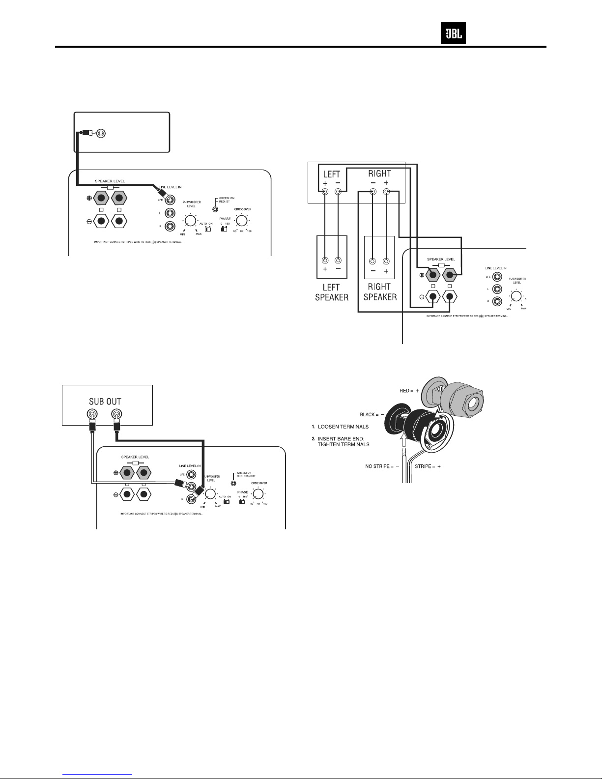
Turn your Subwoofer-Level Control ¢up to the halfway position. If no sound
emanates from the subwoofer, check the AC-line cord and input cables. Are the
connectors on the cables making proper contact? Is the AC plug connected to
a “live” receptacle? Has the Power Switch ªbeen pressed to the “on” posi-
tion? Once you have confirmed that the subwoofer is active, proceed by play-
ing a CD, record or cassette. Use a selection that has ample bass information.
Set the overall volume control of the preamplifier or stereo to a comfortable
level. Adjust the Subwoofer-Level Control ¢until you obtain a pleasing blend
of bass. Bass response should not overpower the room but rather be adjusted
so there is a harmonious blend across the entire musical range. Many users
have a tendency to set the subwoofer volume too loud, adhering to the belief
that a subwoofer is there to produce lots of bass. This is not entirely true. A
subwoofer is there to enhance bass, extending the response of the entire sys-
tem so the bass can be felt as well as heard. However, overall balance must
be maintained or the music will not sound natural. An experienced listener will
set the volume of the subwoofer so its impact on bass response is always
there but never obtrusive.
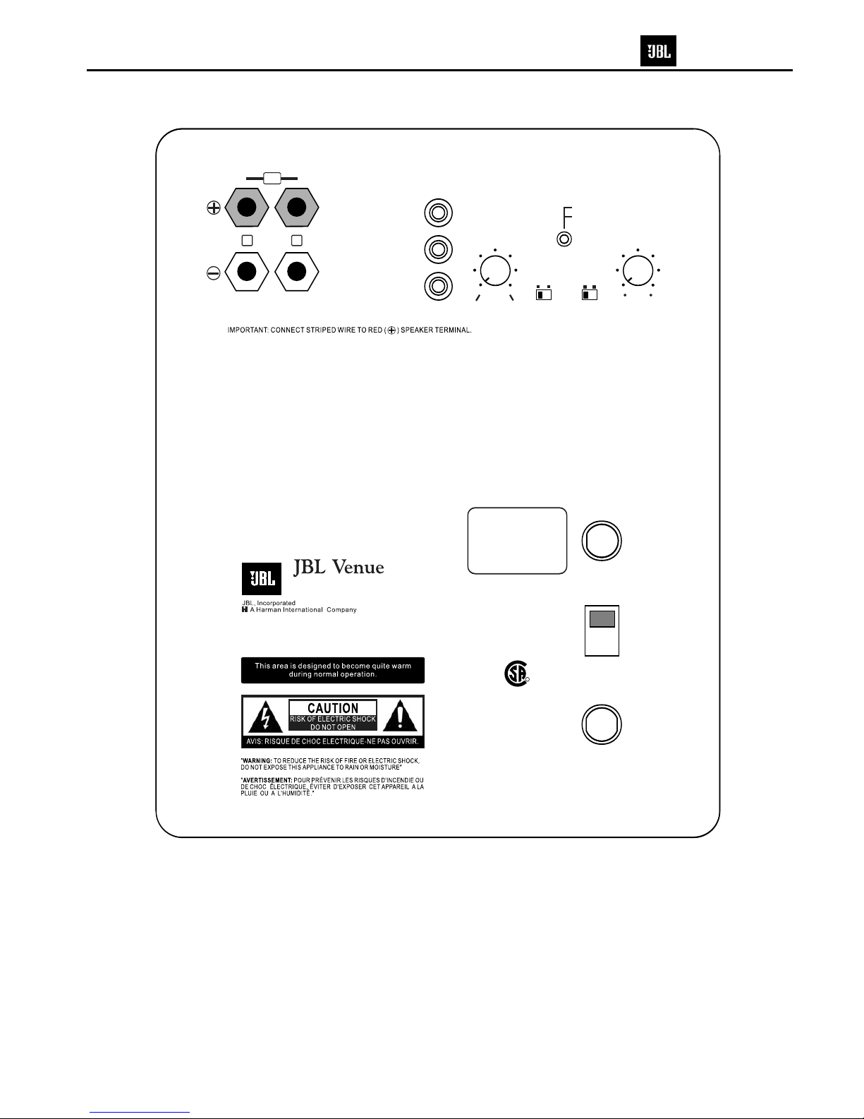
Phase Control
The Phase Switch ¶determines whether the subwoofer speaker’s pistonlike
action moves in and out with the main speakers, 0˚, or opposite the main
speakers, 180˚. Proper phase adjustment depends on several variables such
as room size, subwoofer placement and listener position. Adjust the Phase
Switch to ¶maximize bass output at the listening position.
Crossover Adjustment
The Crossover Adjustment Control •determines the highest frequency at
which the subwoofer reproduces sounds. If your main speakers can comfortably
reproduce some low-frequency sounds, set this control to a lower frequency
setting, between 50Hz and 100Hz. This will concentrate the subwoofer’s
efforts on the ultradeep bass sounds required by today’s films and music.
If you are using smaller bookshelf speakers that do not extend to the lower
bass frequencies, set the Crossover Adjustment Control •to a higher setting,
between 120Hz and 150Hz.
NOTE: This control will have no effect if the LFE/Input ™is used. If you have
a Dolby Digital or DTS processor/receiver, the low-pass frequency is set by the
processor/receiver. Consult your owner’s manual to learn how to view or
change this setting.
The enclosure may be cleaned using a soft cloth to remove fingerprints or to
wipe off dust.
The grille may be gently vacuumed. Stains may be removed with an aerosol
cleaner, following its instructions. Do not use any solvents on the grille.
OPERATION
6
SUB10 Venture Series
7

SUB10 Test Set Up and Procedure
Equipment needed:
•Function/signal generator/sweep generator
•Integrated Amplifier
•Multimeter
•Speaker cables
General Unit Function (UUT = Unit Under Test)
1) From the signal generator, connect line level (RCA) cables to the Subwoofer Line Level Input jacks L/R on
the UUT. Use a Y-cable from a mono source if necessary to connect to both inputs. Do not connect to the
single LFE input.
2) Turn the CROSSOVER control to maximum (150).
3) Turn the LEVEL control on the UUT to completely counterclockwise (MIN).
4) Turn on generator; adjust to 100mV, 50 Hz.
5) Plug in UUT; turn the power switch ON. LED should switch from Red to Green.
6) Turn LEVEL control full clockwise (MAX); immediate and vigorous bass response should be heard and felt
from port tube opening on the bottom.
7) Turn off generator, turn LEVEL control full counterclockwise (MIN), and disconnect RCA cable.
8) Connect one pair of speaker cables to Speaker Level input terminal (IN) on UUT. Cables should be
connected to an integrated amplifier fed by the signal generator.
9) Turn on generator and adjust so that speaker level input at the amplifier is 2.0V, 50 Hz. Turn LEVEL control
full clockwise (MAX).
10)Green LED should light; immediate and vigorous bass response should be heard and felt from the port
tube opening.
Sweep Function
1) Follow steps 8-10 above, using a sweep generator as a signal source.
2) Sweep generator from 20Hz to 300Hz. Listen to the cabinet and drivers for any rattles, clicks, buzzes or
any other noises. If any unusual noises are heard, remove woofers and test.
Driver Function
1) Remove woofer from cabinet (instructions on exploded view drawing); detach + and - wire clips.
2) Check DC resistance of woofer; it should be 5.7 ohms ±10%
3) Connect a pair of speaker cables to driver terminals. Cables should be connected to an integrated amplifier
fed by a signal generator. Turn on generator and adjust so that speaker level output is 5.0V.
4) Sweep generator from 20Hz to 1kHz. Listen to driver for any rubbing, buzzing, or other unusual noises.
SUB10 Venture Series
8

SUB10 Venture Series
9

SUB10 Venture Series
10

SUB10 120V Electrical parts list
Part number Description Qty Reference Designator
PREAMP PCB
Resistors
110-12472j52-e Resistor4.7K 1/2W ±5% CF 52mm (RoHS) 2R201,R20
2
110-16102j26-e Resistor 1K 1/6W ±5% CF 26mm (RoHS) 4 R213,R214,R215,R25
4
110-16103j26-e Resistor10K 1/6W ±5% CF 26mm (RoHS) 15
R209,R212,R216,R217,R220,R221,R222,R228,
R218,R230,R232,R240,R248,R260,R235
110-16104j26-e Resistor100K 1/6W ±5% CF 26mm (RoHS) 4R231,R263,R266,R251
110-16105j26-e Resistor1M 1/6W ±5% CF 26mm (RoHS) 1R25
9
110-16122j26-e Resistor 1.2K 1/6W ±5% CF 26mm (RoHS) 1R26
5
110-16151j26-e Resistor 150Ω1/6W ±5% CF 26mm (RoHS) 1 R253
110-16154j26-e Resistor150K 1/6W ±5% CF 26mm (RoHS) 1R252
110-16183j26-e Resistor18K 1/6W ±5% CF 26mm (RoHS) 1R261
110-16205j26-e Resistor 2M 1/6W ±5% CF 26mm (RoHS) 1R257
110-16223j26-e Resistor22K 1/6W ±5% CF 26mm (RoHS) 3R247,R255,R25
6
110-16333j26-e Resistor 33K 1/6W ±5% CF 26mm(RoHS) 1R24
9
110-16472j26-e Resistor 4.7K 1/6W ±5% CF 26mm (RoHS) 3R208,R207,R25
8
110-16473j26-e Resistor47K 1/6W ±5% CF 26mm (RoHS) 3R219,R250,R26
4
110-16512j26-e Resistor 5.1K 1/6W ±5% CF 26mm (RoHS) 2R210,R211
110-16913j26-e Resistor 91K 1/6W ±5% CF 26mm (RoHS) 4R203,R204,R205,R20
6
116-161002f26-e Metal Film Resistor 10K 1/6W ±1% MF 26mm (RoHS) 3R10,R11,R
9
116-161132f26-e Metal Film Resistor11.3K 1/6W ±1% MF 26mm (RoHS) 2R225,R
7
116-161301f26-e Metal Film Resistor1.30K 1/6W MF 26mm (RoHS) 1R3
116-161372f26-e Metal Film Resistor 13.7K 1/6W MF 26mm (RoHS) 2R226,R22
7
116-161542f26-e Metal Film Resistor 1/6W 15.4K 1% 26mm (RoHS) 2R238,R23
7
116-162433f26-e Metal Film Resistor 243K 1/6W 1% MF 26mm (RoHS) 1R6
116-165601f26-e Metal Film Resistor 5.60K 1/6W ±1% MF26mm (RoHS) 2 R223,R224
116-166042f26-e Metal Film Resistor 60.4K 1/6W±1% MF 1R233
116-169091f26-e Metal Film Resistor 9.09K 1/6W±1% MF 1R234
115-h203b201-e variable Resistor 20KB/2 CROSSOVER 1VR202,
115-h503a101-e variable Resistor D16 50K/1 A (RoHS) LEVEL 1VR201
Capacitors
129-a153j633-e Metallize Capacitor 0.015U 63V MSC 1C224
129-a224j633-e Metallize Capacitor 0.22uF 63V ±5% MSC 3C221,C222,C21
8
129-a334j633-e Metallize Capacitor 0.33uF 63V ±5% MSC 2C1,C3
130-2b221k503-e Disc Capacitor 220P 50V ±10% 12
C200,C204,C205,C207,C213,C210,C211,C212,
C214,C220,C230,C249,
130-3f104z503-e Disc Capacitor 0.1U 50V +80/-20% 9C232,C242,C244,C245, C246,C252,C254,C255,C25
6
130-sl101k503-e Disc Capacitor 100P 50V SL ±10% 1 C6
132-103j503-e mylar Capacitor 0.01uF 50V ±5% 1 C22
3
132-104ja03-e mylar Capacitor 0.1UF 100V ±5% 1 C21
6
132-473ja03-e mylar Capacitor 0.047uF 100V ±5% 2 C215,C21
7
135-3105m50-e electrolytic 1U 50V ±20% 1 C22
8
135-3106m50-e electrolytic10uF 50V ±20% 10 C201,C202,C206,C208, C231,C241,C243,C251,C253,C21
9
135-3107m16-e electrolytic 100uF 16V ±20% 1 C234
135-3226m50-e electrolytic 22U 50V ±20% 2 C225,C
7
135-3227m16-e electrolytic 220U 16V ±20% 1 C233,
129-a334j633-e metalize cap 0.33uF 63V ±5% MSC 1 C2,
Semiconductors
192-027c1815gr-e Transistor 2SC1815GR TOSHIBA(RoHS) NPN 3Q201,Q207,Q208
,
197-031n4148-e diode 100mA 75V SIGNAL 1N4148 13
D201,D202,D203,D204, D205,D206,D207,D208,
D211,D212,D214,D215,D216
199-15000335-e zener diode 3.3V 1/2W 52mm TA 1 D213,
190-06m4558d-e I.C. OPA 4558D (RoHS) DUAL OP-AMP 2U1,U203,
190-16tl074cn-e *I.C TL074CN ST (RoHS) QUAD OP-AMP 2U201,U202,
192-027c1815gr-e Transistor 2SC1815GR TOSHIBA(RoHS) NPN 1Q206,
SUB10 Venture Series
11

Part number Description Qty Reference Designator
PREAMP PCB
195-10204hgw-e double color LED 204HGW 3¢(RoHS) 1D209,
Miscellaneous
162-50062001-e 2PIN 60mm red/black 1for D209,
174-0rca326p-e JACK RCA-326 (RoHS) 1JK201,
174-2wp810a-e SPK JACK 8P red up black down with cap 1 JK203,
175-1c07v01-e wire connector &base7PIN PITCH=2.5mm (RoHS) 1P201,
180-tsv6201-e switch 6PIN DC30V 0.3V AUTO-ON, PHASE 2SW1,SW201
MAIN PCB
Resistors
110-20332jk3-e Resistor 3.3K 2W ±5% portrait short foot7.5m(RoHS) 1R134
113-50s68j00-e Resistor 0.068Ω5W ±5% landscape short foot(RoHS) 1R14
7
116-201001jk3x-e Metal Film Resistor 1.00K 2W ±5% (RoHS) 1R14
8
116-304700jk2x-e Metal Film Resistor 470Ω3W ±5% 10mm (RoHS) 2R501,R50
2
110-14103j26-e Resistor10K 1/4W ±5% CF 26mm 3R503,R504,R510
,
110-14222j26-e Resistor 2.2K 1/4W ±5% CF 26mm TAP (RoHS) 1 R511,
110-14432j26-e Resistor4.3K 1/4W ±5% CF 26mm 1 R506,
110-14472j26-e Resistor 4.7K 1/4W ±5% CF 26mm 1R505,
110-16102j26-e Resistor 1K 1/6W ±5% CF 26mm 1R153,
110-16103j26-e Resistor10K 1/6W ±5% CF 26mm 10 R128,R130,R149,R150,R305,R306,R308,R311,R314,R319,
110-16104j26-e Resistor 100K 1/6W ±5% CF 26mm 3R122,R126,R307
,
110-16153j26-e Resistor15K 1/6W ±5% CF 26mm 1R107,
110-16182j26-e Resistor 1.8K 1/6W ±5% CF 26mm 1R145,
110-16203j26-e Resistor 20K 1/6W ±5% CF 26mm 1R309,
110-16221j26-e Resistor220Ω1/6W ±5% CF 26mm 1R144,
110-16222j26-e Resistor 2.2K 1/6W ±5% CF 26mm 1R102,
110-16223j26-e Resistor 22K 1/6W ±5% CF 26mm 1R316,
110-16333j26-e Resistor33K 1/6W ±5% CF 26mm 1R310,
110-16393j26-e Resistor 39K 1/6W ±5% CF 26mm 1R151,
110-16434j26-e Resistor 430K 1/6W ±5% CF 26mm 1R312,
110-16473j26-e Resistor 47K 1/6W ±5% CF 26mm 2R106,R129,
110-16474j26-e Resistor 470K 1/6W ±5% CF 26mm 1R127,
110-16562j26-e Resistor 5.6K 1/6W ±5% CF 26mm 1R152,
110-16621j26-e Resistor 620Ω1/6W ±5% CF 26mm 1R160,
110-16751j26-e Resistor 750Ω1/6W ±5% CF 26mm 1R315,
110-16755j26-e Resistor 7.5M 1/6W ±5% CF 26mm 1R313,
116-161002f26-e metal film Resistor10K 1/6W ±1% MF 26mm 2R301,R303,
116-161202f26-e metal film Resistor 12.0K 1/6W ±1% MF 1R302,
116-162200f26-e metal film Resistor 220Ω1/6W ±1% MF 1R317,
116-162202f26-e metal film Resistor 22.0K 1/6W ±1% MF 1R318,
Capacitors
138-5478m80-e large aluminum ec 4700uF 80V ±20% 85℃(RoHS) 2C501,C50
2
132-a103ja03-e Mylar Capacitor 0.01u 100V (RoHS) 2C103,C10
4
132-103kd00-e mylar Capacitor 0.01U 400V +/-10% long foot (RoHS) 1C500
130-3f104z503-e base capacity 0.1U 50V +80/-20% 6C107,C117,C122,C144, C320,C322
130-sl101k503-e base Capacitor 100P 50V SL ±10% 3C302,C303,C306
,
132-103j503-e mylar Capacitor0.01uF 50V ±5% 2C305,C317,
132-104ja03-e mylar Capacitor 0.1UF 100V ±5% 3C123,C503,C504
,
132-273ja03-e mylar Capacitor0.027UF 100V ±5% 1C143,
135-3106m50-e electrolytic Capacitor 10uF 50V ±20% 2C319,C321,
135-3107m10-e electrolytic cap 100U 10V ±20% 2C114,C115,
135-3107m35-e electrolytic cap100U 35V ±20% 2C507,C508,
135-3225m50-e electrolytic cap 2.2U 50V ±20% 1C509,
135-3226m16-e electrolytic cap 22U 16V ±20% 1C304,
SUB10 Venture Series
12

Part number Description Qty Reference Designator
MAIN PCB
135-3226m50-e electrolytic cap 22U 50V ±20% 2C505,C506,
135-3227m16-e electrolytic cap 220U 16V ±20% 1C118,
135-3476m16-e electrolytic cap47U 16V ±20% 1C318,
Semiconductors
190-16tl074cn-e *I.C TL074CN ST (RoHS) DUAL OP-AMP 1U301
192-161tip31c-e Transistor TIP31C SGS (RoHS) NPN 1Q501
192-161tip32c-e TransistorTIP32C SGS (RoHS) PNP 1 Q502
197-00kbu606g-e diode6A 800V KBU606G (RoHS) BRIDGE 1D501
197-141n4004-e diode1N4004 (RoHS) 2D110,D504
192-027c1815gr-e Transistor 2SC1815GR TOSHIBA(RoHS) NPN 5Q108,Q109,Q113,Q301, Q302,
192-027c2235y-e Transistor2SC2235Y TOSHIBA (RoHS) NPN 1Q111,
192-028a1015gr-e Transistor 2SA1015GR TOSHIBA(RoHS) PNP 3Q101,Q107,Q112,
192-1572n5551-e TransistorFSC 2N5551 (RoHS) NPN 2Q114,Q115,
192-1582n5401-e TransistorFSC 2N5401 TO-92 (RoHS) PNP 1Q503,
197-031n4148-e diode100mA 75V SIGNAL 1N4148 4D102,D103,D104,D105,
199-15000625-e zener diode HZ6C2 RENESAS (6.2v) 1D101,
199-15001605-e zener diode HZ16-2 RENESAS (16v) 1D502,
Miscellaneous
120-1000003-e inductor10W AI YT-C3104-005 1CRHW354708LTB (RoHS) 2FB1,FB2
109-1ttc802j0-e Thermister TTC-802(JS) NTC long foot(RoHS) 1 TH1
162-50129001-e CABLE ASS'Y wire 120mm AWG28 WHT (RoHS) 1W201
171-urwh124d-e Relay RWH-SH-124D (1600 ohm) (RoHS) 1RL1
175-1d02v01-e Wire connector&base 2PIN PITCH=3.96mm (RoHS) 1M100
175-1d03v01-e Wire connector&base 3 PIN PITCH=3.96mm (RoHS) 1M500
CLASS D ASS'Y PCB (Replacment of entire module is recommended, part# 051-B00012A-E).
Resistors
118-120610r0j-e SMDresistor 10.0Ω1206 5% (RoHS) 2 R22,R23
118-12061001j-e SMDresistor 1.00K 1206 5% (RoHS) 4 R2,R11,R29,R30
118-12061002j-e SMDresistor 10.0K 1206 5% (RoHS) 3 R7,R9,R25
R31,R32,R33,R34,R35,R36,R37,R38
R39,R40,R41,R42,R43,R44,R45,R46
118-12062002j-e SMDresistor 20.0K 1206 5% (RoHS) 1 R26
118-12062201j-e SMDresistor 2.20K 1206 5% (RoHS) 3 R6,R13,R16
118-12062701j-e SMDresistor 2.70K 1206 5% (RoHS) 1 R10
118-12063000j-e SMDresistor 300.0Ω1206 5% (RoHS) 1 R24
118-12063301j-e SMDresistor 3.30K 1206 5% (RoHS) 4 R14,R15,R27,R28,
118-12063902j-e SMDresistor 39.0K 1206 5% (RoHS) 1 R3
118-120647r0j-e SMDresistor 47.0Ω1206 5% (RoHS) 2 R20,R21
118-12064700j-e SMDresistor 470Ω1206 5% (RoHS) 1 R8,
118-12064701j-e SMDresistor 4.70K 1206 5% (RoHS) 3 R1,R5,R12,
118-12064702j-e SMDresistor 47.0K 1206 5% (RoHS) 1 R17
118-12064704j-e SMDresistor 4.70M 1206 5% (RoHS) 1 R4,
Capacitors
128-e106ma01k-e crossver cap 10UF 100V 20% 105℃long foot (RoHS) 2 C16,C17
141-c0220k50-e SMD Capacitor 22pF 50V 10% 1206 SMT NPO (RoHS) 1C5,
141-c0561k50-e SMD Capacitor 560pF 50V 10% 1C6,
141-c5104m50-e SMD Capacitor 1206 Y5V 0.1uF 50V ±20% (RoHS) 8C2,C3,C7,C8,C9,C10,C11,C15,
141-c7223k50-e SMD Capacitor 0.022uF 50V 10%1206 X7R (RoHS) 1C13,
141-c0101k50-e SMD Capacitor 100pF 50V 10% 1206 NP0 (RoHS) 1C4,
141-d7104ka0-e SMD Capacitor 0.1uF 100V 10% 1210 X7R (RoHS) 2C12,C14
141-d7104kb5-e SMD Capacitor 0.1uF 250V 10% 1210 X7R (RoHS) 4C1,C18,C19,C20,
118-12061201j-e SMDresistor 1.20K 1206 5% (RoHS) 16
SUB10 Venture Series
13

Part number Description Qty Reference Designator
CLASS D ASS'Y PCB (Replacment of entire module is recommended, part# 051-B00012A-E).
Semiconductors
190-16tl072dts-e SMD I.C. TL072CDT SGS THOMSON DUAL OP-AMP 1IC1,
192-09124126qs-e SMD Transistor 2SC2412K-T146Q/R 3Q1,Q4,Q5,
192-09139066rs-e SMD Transistor 2SC3906K-T146R ROHM 2Q2,Q8,
192-09210376qs-e SMD Transistor 2SA1037K-T146Q/R 2Q7,Q9
192-09215146rs-e SMD Transistor2SA1514K-T146R ROHM 2Q3,Q6,
197-03rls4148s-e SMD Transistor RLS4148-TE11 ROHM 6D1,D2,D3,D4,D5,D6,
192-232irf9640-e FET IRF9640 IR P-CH TO220(RoHS) 1 Q10
192-233f640n-e Transistor IRF640N INTERNATIONA(RoHS) 1 Q11
199-15000563s-e SMD ZENER 5.6V 5% PHILIPS BZX84-C5V6 (RoHS) 2 Z1,Z2,
199-1500120s-e SMD ZENER 12V 5% PHILIPS BZX84-C12 (RoHS) 2Z5,Z6,
199-15001503s-e SMD ZENER 15V 5% PHILIPS BZX84-C15 (RoHS) 2Z3,Z4
Miscellaneous
122-14121m4191-e Ferrite core LS-A6206-ST EFD-30 (RoHS) 1L1
122-14350j4180-e chock coil35uH Ferrite Core 25 Milliohm (RoHS) 1L2
175-9f40hr2-e wire connector & base 40PIN (RoHS) 0.2
MISCELLANEOUS/MECHANICAL
350-FM04012D106-E ψ4*12 wood screw(RoHS) 4
352-AM03010D066-E ¢3*10 Ptype tapping screw(RoHS) 3
352-AM03008D041-E ¢3*8 Btypetapping screw (RoHS) 4
150-r4055900-e power Xformer I/P:120V/60Hz TT0900008720 (RoHS) 1 T501
152-u602015-e line cord polar SVT FT-2 6FT double insulator (RoHS) 1
154-k31505t0-e fuse 3.15A 250V 30mm UL/CSA /PSE (RoHS) 1 F501
155-63032i-e fuse holderHTB-32I 30mm UL/CSA (RoHS) 1 for F501
180-pbr12c11s-e power switch PUSH BR12C11S (RoHS) 1 SW501
162-10082007-e WIRE RED 18AWG 80mm 8mm#1015 (RoHS) 1
362-FE-00013-0LAE PCB support L TYPE t=1.6mmS.P.C.C 89*9*1.6T (RoHS) 2
311-ABS-00028-0BAE LEVEL KNOB 46077-W P.V.C.(RoHS) 2
306-ABS-00004-0BAE rear Plastic housing 268*213*102 A.B.S UL (RoHS) 1
176-wjce1-e wire connector pinCE-1 (RoHS) 1
333-EVA-00096-0BAE EVA gasket wide side213*15*2.0mm(RoHS) 2
333-EVA-00097-0BAE EVAgasket wide side213*15*1.0t (RoHS) 2
333-EVA-00132-0BAE EVA gasket long side238*15*2.0mm (RoHS) 2
333-EVA-00133-0BAE EVAgasket long side238*15*1.0t (RoHS) 2
333-EVA-00220-0BAE EVAgasket long side225*15*1t UL(RoHS) 1
333-EVA-00188-0BAE EVA gasket 170x5x1t (RoHS) 1
130-3f104z503-e disc capacitor 0.1U 50V +80/-20% TAP(RoHS) 1 C110
193-201815t2-e insulator (RoHS)
352-HM03012D086-E ¢3*12 Btypetapping screw black (RoHS)
317-000-00037-0LAE panel M3 solder t=0.3 (RoHS) 1
323-AL-00056-0LAE heat sink 83.5*50.5*27.5H 1
333-EVA-00219-0BAE EVAgasket 150*15*1t UL(RoHS) 1
351-AM03008A078-E M3*8 machine screw (RoHS) 6
162-a040d005-e spkr wire red and black#1015 add #205 250 pin(RoHS) 1
302-AL-00020-1LCE rear board 270*215*2.5T SUB10 AL (RoHS) 1
335-NYL-05015-0BAE wire clip SB4F-2 black(RoHS) 2
SUB10 Venture Series
14

SUB10 Venture Series
15

SUB10 Venture Series
16

SUB10 Venture Series
17

SUB10 Venture Series
18

SUB10 Venture Series
19
Other manuals for Balboa SUB10
3
This manual suits for next models
1
Table of contents
Other JBL Subwoofer manuals