2-2
Before Entering the Cab
The following checks should be made each time you return
to the machine after leaving it for any period of time. We
advise you also to stop the machine occasionally during
long work sessions and do the checks again. All these
checks concern the serviceability of the machine. Some
concern your safety. Get your service engineer to check and
correct any defects.
!WARNING
Walking or working under a raised boom and dipper is
hazardous. You could be crushed by the boom and
dipper or get caught in the linkages. Lower the boom
and dipper before doing these checks. If you are new to
this machine, get an experienced operator to lower the
boom and dipper for you.
If there is nobody to help you, study this handbook until
you have learned how to lower the boom and dipper.
8-2-1-1
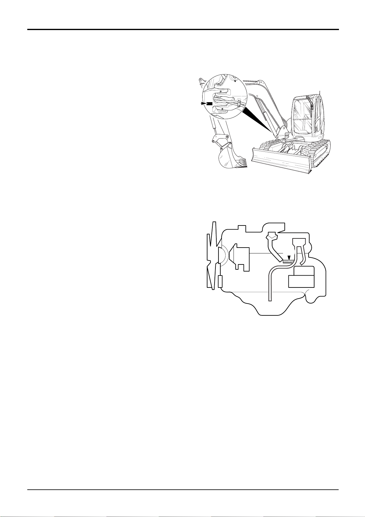
!CAUTION
On machines fitted with hose burst protection valves, the
attachments cannot be lowered with the engine stopped.
On these machines start the engine and lower the
attachments before doing the walk round inspection.
2-2-3-5
!CAUTION
The hydraulic oil filler cap may be hot if the machine has
recently been used. If this is the case, wear suitable
gloves when tightening or loosening this cap.
1 Check for Cleanliness
aClean the windows, light lenses and rear view
mirrors.
bRemove dirt and debris, especially from around the
linkages, rams, pivot pins and radiator grille.
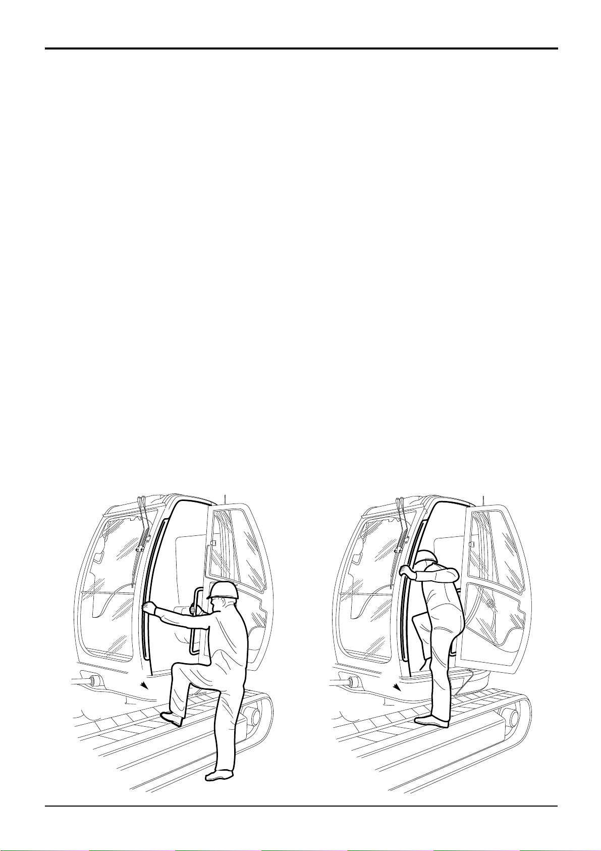
cMake sure the cab step and handholds are clean
and dry.
dClean all safety decals. Replace any that are missing
or cannot be read.
2 Check for Damage
aInspect the machine generally for damaged and
missing parts.
bMake sure that all pivot pins are secured in place.
cInspect the windows for cracks and other damage.
dCheck for oil, fuel and coolant leakages beneath the
machine.
eCheck the tracks (rubber). Check for cut rubber and
penetration by sharp objects. Do not use a machine
with damaged tracks.
3 Check for Security
aCheck the security of the hinged covers on the
engine compartment and hydraulic compartment.
bMake sure that the hydraulic oil and diesel fuel filler
caps are both tightly closed. REMEMBER THAT THE
HYDRAULIC FILLER CAP MAY BE HOT IF THE
MACHINE HAS RECENTLY BEEN USED. (We also
recommend that you lock the fuel filler cap.)
Section 1 General Information
9803/9330
Section 1
2-2
Issue 1
Operation